1
University of West Bohemia
Faculty of Applied Sciences
Department of Computer Science and Engineering
MASTER THESIS
Pilsen, 2013
Lukáš Volf
University of West Bohemia
Faculty of Applied Sciences
Department of Computer Science and
Engineering
Master Thesis
Application for the Localization of
Resource Script Files
Pilsen, 2013
Lukáš Volf
Declaration
I hereby declare that this master thesis is completely my own work and that I
used only the cited sources.
Pilsen, May 14, 2013
__________________
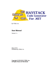
Abstract
The paper focuses on the development of a tool that would make the
localization of Resource Script files easier. It explains the construction of the
Resource Script parser and then provides an overview of the technologies that
were used to build the application. The technologies described in this paper
include the Windows Presentation Foundation and the Model-View-ViewModel
application architecture.
The second part of the paper focuses on the implementation of the parser and
the application itself. It shows the architecture of the application and describes
the functionality of the tool and the user interface. The result of the project is an
application that can localize Resource Script files using the translated strings
from previous versions of the localization.
Acknowledgements
I would like to thank Karel Nykles for his valuable advice, suggestions and
support during my work on the project.
I would also like express my gratitude to my supervisor, Pavel Herout, for his
kind guidance and support from the beginning to the very end of my master
thesis. I truly appreciate his helpful advice and generous help.
Lastly, I would like to thank Lucie Nevřelová for correcting the English
language of this thesis.
Table of Contents
1
Introduction ......................................................................................................... 1
2
Resource Script Files ........................................................................................... 2
2.1
3
Dialog Units ................................................................................................. 2
Parsing .................................................................................................................. 4
3.1
Lexical Analysis........................................................................................... 4
3.2
Grammars..................................................................................................... 5
3.2.1
3.3
Grammar Types....................................................................................... 5
3.3.1
Parsing .......................................................................................................... 6
4
LR Parsers................................................................................................. 7
Windows Presentation Foundation .................................................................. 8
4.1
Device Independent Pixels ........................................................................ 8
4.2
Architecture ................................................................................................. 8
4.3
Extensible Application Markup Language ........................................... 10
4.4
Dependency Properties ............................................................................ 11
4.5
Data Binding .............................................................................................. 11
4.6
Data Templates .......................................................................................... 13
4.7
Tasks ........................................................................................................... 14
4.7.1
5
6
Async ...................................................................................................... 14
Model-View-ViewModel ................................................................................. 16
5.1
View ............................................................................................................ 16
5.2
View Model ................................................................................................ 17
5.3
Model .......................................................................................................... 17
5.4
Commands ................................................................................................. 17
Localization ........................................................................................................ 19
6.1
Existing Tools ............................................................................................ 19
6.1.1
Sisulizer .................................................................................................. 19
6.1.2
RCLocalize ............................................................................................. 20
6.1.3
6.2
RC-WinTrans ......................................................................................... 21
7
Localization of the Resource Script Files ............................................... 23
Parser .................................................................................................................. 25
7.1
C# LEX ........................................................................................................ 25
7.2
C# CUP ....................................................................................................... 26
7.3
Implementation ......................................................................................... 26
7.3.1
Scanner Implementation ...................................................................... 27
7.3.2
Parser Implementation ......................................................................... 28
Build Events ............................................................................................... 29
7.5
Error Handling .......................................................................................... 30
8
7.4
Application Architecture ................................................................................. 31
8.1
9
Model-View-ViewModel Helper Classes .............................................. 32
8.1.1
Interaction Service................................................................................. 32
8.1.2
View Model Base Class ........................................................................ 33
User Interface ..................................................................................................... 35
9.1
Main Window ............................................................................................ 35
9.1.1
Ribbon ..................................................................................................... 35
9.1.2
Project Tree............................................................................................. 37
9.1.3
Tabs ......................................................................................................... 39
Wizard ........................................................................................................ 40
9.3
Localization Tab ........................................................................................ 42
10
9.2
9.3.1
Data Grid ................................................................................................ 42
9.3.2
Visual Editor .......................................................................................... 43
9.3.2.1
Adorner .......................................................................................... 44
9.3.2.2
Canvas ............................................................................................ 46
9.3.2.3
Editor Control ................................................................................ 46
Localization Process.......................................................................................... 50
10.1
Localizable Item Identification ................................................................ 50
Languages .................................................................................................. 51
10.3
Bing Translator .......................................................................................... 52
11
10.2
Setup ................................................................................................................... 54
11.1
12
Application Files ....................................................................................... 54
Testing ................................................................................................................ 55
12.1
12.1.1
Lexer Testing...................................................................................... 55
12.1.2
Grammar Testing .............................................................................. 55
12.2
Application Testing .................................................................................. 56
12.2.1
User Interface Testing ....................................................................... 56
12.2.2
Functionality Testing ........................................................................ 57
12.3
13
Parser Testing ............................................................................................ 55
Results ......................................................................................................... 57
Further Enhancements ..................................................................................... 58
Conclusion ................................................................................................................. 59
A
User Guide ....................................................................................................... A-1
B
Resource Script .................................................................................................B-1
C
Content of the DVD ........................................................................................ C-1
Table of Figures
Figure 1WPF architecture .......................................................................................... 9
Figure 2 XAML code sample ................................................................................... 10
Figure 3 Binding Types ............................................................................................ 12
Figure 4 Binding sample .......................................................................................... 13
Figure 5 Task.WhenAll sample code ...................................................................... 15
Figure 6 MVVM pattern ........................................................................................... 16
Figure 7 Sisulizer 3 .................................................................................................... 20
Figure 8 RCLocalize 7.06 .......................................................................................... 21
Figure 9 RC-WinTrans 9.2........................................................................................ 22
Figure 10 Resource Parser class diagram .............................................................. 27
Figure 11 Layer diagram .......................................................................................... 31
Figure 12 Interaction Service class diagram .......................................................... 33
Figure 13 ViewModelBase class diagram .............................................................. 34
Figure 14 .NET 4.5 Ribbon rendering issues ......................................................... 36
Figure 15 .NET 4.5 Ribbon without the Ribbon Window ................................... 36
Figure 16 Tree View model class diagram ............................................................ 37
Figure 17 Tree View sample .................................................................................... 38
Figure 18 Tabs class diagram .................................................................................. 40
Figure 19 Project wizard class diagram ................................................................. 41
Figure 20 Data Grid code sample ........................................................................... 43
Figure 21 Adorned elements with the resize handles ......................................... 44
Figure 22 Adorner class diagram............................................................................ 45
Figure 23 resizing adorner code sample ................................................................ 46
Figure 24 Control hierarchy of the Visual Editor ................................................. 48
Figure 25 Dialog editor View Model class diagram............................................. 49
Figure 26 Bing Localization provider class diagram ........................................... 53
Figure 27 Welcome screen ..................................................................................... A-1
Figure 28 Installation path selection..................................................................... A-2
Figure 29 Installation summary ............................................................................ A-2
Figure 30 Installation completed .......................................................................... A-3
Figure 31 Main window of the application ......................................................... A-4
Figure 32 Loading project ...................................................................................... A-4
Figure 33 New tab in the backstage view ............................................................ A-5
Figure 34 Open tab in the backstage view ........................................................... A-6
Figure 35 Save tab in the backstage view ............................................................ A-6
Figure 36 Home tab in the ribbon ......................................................................... A-7
Figure 37 Localize tab in the ribbon ..................................................................... A-7
Figure 38 Project tree .............................................................................................. A-8
Figure 39 Create new project button .................................................................... A-8
Figure 40 New project wizard - Project tab ......................................................... A-9
Figure 41 New project wizard - Version tab ..................................................... A-10
Figure 42 New project wizard - Language tab ................................................. A-10
Figure 43 New project wizard - Files tab ........................................................... A-11
Figure 44 New project wizard - Summary tab.................................................. A-11
Figure 45 Add version wizard ............................................................................ A-12
Figure 46 Add language wizard ......................................................................... A-13
Figure 47 Add files dialog.................................................................................... A-13
Figure 48 Resource Script view ........................................................................... A-14
Figure 49 Localize wizard .................................................................................... A-15
Figure 50 Localize tab ........................................................................................... A-15
Figure 51 Dialog editor......................................................................................... A-17
1 Introduction
Applications written in C/C++ for Microsoft Windows operating systems use
resource files to define dialogs, menus, strings and other resources such as icons
and various metadata. These resources are compiled and linked with the
application binary, and the resources contained inside are accessible in runtime
by calling a subset of Application Programming Interface (API) functions.
Usually, each application contains only one resource file created by the developer
that defines strings in the main application language. In order to add support for
multiple languages, the resources must be translated.
There are two approaches to the localization of native applications on Microsoft
Windows: the localization of the compiled binary or the localization of the source
Resource Script. The first approach is more common as it does not require having
the source files. The second approach, on the other hand, allows us to build the
localization as a part of the automated building process and to include it in the
installation package. In addition, the second approach is more flexible when it
comes to updating the localization to a newer version of the application where
some originally translated resources might have been changed.
It is necessary to create a tool to make the localization of resource files easier by
comparing the current and all the previous versions of the original and localized
resource files. It is supposed to build a list of items to localize, use previous
versions of the localization to translate strings that have not changed, and
highlight only the strings that need user’s attention. It should also help with the
translation of the remaining strings using the Bing Translator, an online translator
from Microsoft.
The main reason to build this tool is to help with the Czech localization of the
OpenAFS client for Microsoft Windows operating systems. This software is being
continuously improved and all the resource files that had already been localized
in the previous versions of the application are usually not compatible with the
latest version due to the changes in the original Resource Script.
1
2 Resource Script Files
A resource file is a text file with the extension .rc. This file includes a set of
definitions that describe various resources, such as a dialogs or string tables. The
Resource Script supports a subset of preprocessor directives, defines and pragmas
in the script. Resources such as an icon or bitmap can exist in a separate file; the
Resource Script only contains a link to an external file along with the definition of
its resource type [1].
Resource files are compiled by the Microsoft Windows Resource Compiler. This tool
is commonly used in the building process of Windows applications. The output of
this compiler is stored in a .res file. Compiled resources are linked into the
application executable where they are accessible in runtime by calling a subset of
Win32 API functions.
Resource definition statements can be divided into three categories as follows:
resources, controls and statements.
Resources are always defined on the top level of the Resource Script. They can
contain other resource types such as controls and statements, but they cannot be
placed inside other resource elements. Resources include, but are not limited to
STRINGTABLE (B.1.8), DIALOG (B.1.3), MENU (B.1.5), VERSIONINFO (B.1.9),
etc.
Controls can be placed onto the dialog defined by the DIALOG (B.1.3) or
DIALOGEX (B.1.4) resource. There are four categories of controls: generic, static,
button and edit controls. They have minor differences in syntax, but all the
controls have their position on the dialog.
Statements are common attributes that can be included in the definition of almost
any resource except controls. Statements include attributes such as CAPTION
(B.3.1), FONT (B.3.5), LANGUAGE (B.3.6), STYLE (B.3.9) etc. For more
information about syntax of various resource types refer to the section B.
2.1 Dialog Units
Resources such as DIALOG, DIALOGEX and all the controls have a size and a
position defined in the script. This position is stored in Dialog Units (DU). These
units depend on the dialog font and its size. If no font is specified, a default
2
system font and a default size are used. DU help the developer to create scalable
dialogs where all elements are positioned relatively and scaled correctly
depending on the font size. In order to convert standard device independent
pixel coordinates to the dialog units, we need to get the Dialog Base Units (DBU)
first. There are three methods of getting the DBU:
1) The first approach is using a call to the GetDialogBaseUnits function.
However, this function does not allow us to specify the font of the dialog
– it uses a default system font to calculate the base units, which means it
is not suitable to be used in a dialog editor.
2) The second approach uses the MapDialogRect function to get the
coordinates. Because this function needs the handle (HWND) of the target
dialog as one of its parameters, it was not possible to use this approach.
3) The last approach uses Win32 API functions to retrieve the character
height and calculates the average character width by measuring the text
extent of the string that contains the entire English alphabet.
Essentially, the code creates a new device context based on the default one, then
it creates a new font that uses the typeface of the dialog as well as the specified
font size, selects the font to the recently created device context and then calls the
GetTextMetricsW function to get the font height.
𝑏𝑎𝑠𝑒𝑢𝑛𝑖𝑡𝑦 = 𝑓𝑜𝑛𝑡 ℎ𝑒𝑖𝑔ℎ𝑡
Because the average font width returned by this function is not precise enough
according to the MSDN [1], we need to call the GetTextExtentExPointW
function and supply the entire English alphabet in lower and upper case as a
string parameter of 52 characters. Then we get the horizontal base unit as follows:
𝑠𝑡𝑟𝑖𝑛𝑔 𝑤𝑖𝑑𝑡ℎ
26 + 1
𝑏𝑎𝑠𝑒𝑢𝑛𝑖𝑡𝑥 =
2
In order to convert the dialog units into pixels, we can use the following
equations [1]:
𝑝𝑖𝑥𝑒𝑙𝑥 =
𝑑𝑖𝑎𝑙𝑜𝑔𝑢𝑛𝑖𝑡𝑥 ∙ 𝑏𝑎𝑠𝑒𝑢𝑛𝑖𝑡𝑥
4
𝑝𝑖𝑥𝑒𝑙𝑦 =
𝑑𝑖𝑎𝑙𝑜𝑔𝑢𝑛𝑖𝑡𝑦 ∙ 𝑏𝑎𝑠𝑒𝑢𝑛𝑖𝑡𝑦
8
3
3 Parsing
3.1 Lexical Analysis
Lexical analysis, also called scanning, is a process of splitting the input into
tokens. A token is a group of characters that has some meaning in the context of
the source file, e.g. a comment, a string, a number etc. Lexical analysis can
determine whether the input consists of valid tokens of the language, but it
cannot detect whether they appear in the correct order.
There are two common approaches to implementing a scanner. The first
approach is to write it by hand, which means creating a program that consists of
a loop with a switch/case statement inside, that processes scanned characters one
by one and determines the meaning of these characters. This is acceptable for a
reasonable set of token types, but according to the Lexical Analysis written by
Maggie Johnson and Julie Zelenski [2] is the verifications of such an amount of
code much harder. The other approach of creating a lexer is using regular
expressions and finite automata.
Regular expression, sometimes also called regex or regexp, is a string that is made
of symbols describing a search pattern. Expressions provide a powerful, efficient
and flexible tool for text processing. They enable us to parse quickly through
large amounts of text in order to find specific patterns. Formally, regular
expressions can be defined by the following set of recursive rules [2]:
1) Every symbol of ∑ is a regular expression
2) ε is a regular expression
3) if r1 and r2 are regular expressions, so are:
a.
(r1)
b. r1r2
c. r1 | r2
d. r1*
4) Nothing else is a regular expression
Finite automata are used internally in the building process of a scanner.
According to the Lexical Analysis [2], a finite automaton has:
1) A finite set of states with one designated as the initial state or start state,
and some (maybe one) are designated as final states.
4
2) An alphabet ∑ of possible input symbols.
3) A finite set of transitions that specifies what state to go next for each state
and for each symbol of the input alphabet.
Based on the Kleene’s theorem [3] saying that regular expressions have the same
expressive power as finite automata, we can translate any regular expression into
a finite automaton that accepts its language, and we can take a finite automaton
and convert it into an equivalent language. This enables us to create a nondeterministic automaton from the given regular expression, and using a subset
construction, we can translate that into a deterministic finite automaton, which is
in fact the scanner.
3.2 Grammars
A grammar is a powerful tool for describing languages. It consists of a set of rules
called productions P that describe how to replace symbols. There are two types
of symbols – terminal T and nonterminal N. A terminal is an actual word in a
language that cannot be expanded further. A nonterminal, on the other hand, is
a grammar symbol that can be expanded to a sequence of other symbols. These
symbols can be either terminal or nonterminal. A set of terminal symbols is called
a terminal alphabet. The remaining symbols are called nonterminal alphabet.
Together they form the alphabet of the language.
A sequence of applications of the expansions that produces a string of terminals
is called a derivation. There are two types of derivation – the leftmost and the
rightmost. When we replace the leftmost nonterminal in each step, we are talking
about the leftmost derivation, and similarly when we replace the rightmost
nonterminal, we are talking about the rightmost derivation. To start applying the
rules we need to know which rule to begin with. This start symbol S can be
defined explicitly, or we can assume it is the first production in the set.
3.2.1 Grammar Types
There are four types of grammars according to the American linguist Noam
Chomsky [4]:
Type 0
These free or unrestricted grammars are the most general type of grammars
according to Chomsky. There are no restrictions applicable on what will be on
5
the right side of the productions. Productions are in the form1 𝛼 → 𝛽 where both
𝛼 and 𝛽 are arbitrary strings of symbols of the alphabet. The symbol 𝛼 must be
nonterminal and must not be null.
Type 1
These are context-sensitive grammars meaning that we can apply the
productions only in the specified context. Productions of this type of grammars
must be in the form 𝛼𝑋𝛽 → 𝛼𝛾𝛽, where α, β are arbitrary strings of symbols in
the alphabet with 𝛾 non-null and X a single nonterminal symbol.
Type 2
Context-free grammars are made of productions in the form 𝑋 → 𝛾. The symbol
𝛾 is an arbitrary string of symbols in the alphabet and X is a single nonterminal
symbol.
Type 3
The last type of grammars according to Chomsky is regular grammars. They are
in the form 𝑋 → 𝑤, 𝑋 → 𝑤𝑌 and 𝑋 → 𝜀 where X and Y are nonterminal symbols
and w is a terminal one. The left-hand side must be a nonterminal and the right
side can be either empty, a single terminal alone or followed by a single
nonterminal.
Most programming languages are of the type 2. Although every type 2 grammar
is also a type 1 grammar, and every type 1 grammar is a type 0 grammar which
is the most powerful in the terms of expression power, we cannot create a parser
for type 1 and type 0 grammars. Fortunately, in order to create a parser for the
Resource Script, we can use the type 2 grammar to describe the language.
3.3 Parsing
There are two strategies of parsing [5]: top-down parsing and bottom-up parsing.
Top-down parsing begins with the target symbol of the grammar and attempts
to produce a string of terminal symbols that is identical to a given string. Bottom-
Conventions state that we use Greek letters or lower-case letters u-z for strings, numbers or
lower-case letters a-t for terminal symbols and identifiers or upper-case letters for nonterminal
symbols.
1
6
up parsing, on the other hand, starts building the parse tree from the terminals
and applies the productions in reverse in order to get to the root nonterminal.
Bottom-up parsing algorithms are more powerful than top-down methods [6],
but the constructions required are also more complex. It is hard to write this type
of parser by hand, but there are tools that can make the process a lot easier. One
of the tools is C# CUP that is described in the section 7.2.
Generally, bottom-up parsers use shift and reduce operations while parsing the
input. Reduce operation tries to find a right side of the production on the stack
in order to replace it with the left side of the production. If no such right side is
found and there are other tokens in the input, the shift operation is performed.
This operation pushes a token from the input onto the stack. When there are no
tokens left on the input, and we cannot perform a reduce operation because the
tokens in the stack do not match any of the right sides of the productions, the
parser throws an error.
3.3.1 LR Parsers
LR parsers are an example of shift-reduce bottom-up parsers. They scan the input
from left to right and perform the rightmost derivation. Internally, the LR parser
constructs two tables: the action table and the goto table. These tables are usually
combined into a single table, where the action table specifies the actions for
terminals and the goto table defines actions for non-terminals. These tables can be
quite large in case of a LR parser and they grow rapidly with the increasing
number of look-ahead tokens.
In order to minimize the size of the table, we can limit the number of grammars
to which the parser is applicable. According to the Theory and Practice of
Compiler Writing [5], there are three main types of LR parsers with one symbol
of look-ahead: SLR(1), LALR(1) and LR(1). These parsers are lined in an ascending
order based on the size of the parsing tables. LALR(1) parsers are a good
compromise that does not have an enormous parsing table while keeping the
ability to parse most of the grammars.
7
4 Windows Presentation Foundation
The Windows Presentation Foundation (WPF) is a next-generation presentation
framework for designing Windows applications that can take advantage of
modern graphics hardware. Instead of rendering the user interface using older
GDI/GDI+, WPF utilizes DirectX. As a result, the developer can use gradients,
animations, transparency and even 3D. It also means that WPF applications can
run much faster because all the drawing work is done by the GPU.
Another aspect of using WPF is that all rendered content is resolution
independent. WPF renders all elements based on the current system DPI setting,
which means the content is always properly scaled. To do that, WPF uses device
independent pixels to specify dimensions, position, margins, etc.
4.1 Device Independent Pixels
A WPF window and all elements are measured and positioned by using the
device independent pixels. These units depend on the currently selected system
DPI, which means the resulting user interface will adjust itself based on the user’s
settings. According to the MSDN [7], the device independent units are defined as
follows:
1 𝑑𝑒𝑣𝑖𝑐𝑒 𝑖𝑛𝑑𝑒𝑝𝑒𝑛𝑑𝑒𝑛𝑡 𝑢𝑛𝑖𝑡 =
1
𝑖𝑛𝑐ℎ
96
To convert device independent units to device pixels, the following equation [8]
can be used:
[𝑃ℎ𝑦𝑠𝑖𝑐𝑎𝑙 𝑈𝑛𝑖𝑡 𝑆𝑖𝑧𝑒] = [𝐷𝑒𝑣𝑖𝑐𝑒 𝐼𝑛𝑑𝑒𝑝𝑒𝑛𝑑𝑒𝑛𝑡 𝑈𝑛𝑖𝑡 𝑆𝑖𝑧𝑒] ∙ [𝑆𝑦𝑠𝑡𝑒𝑚 𝐷𝑃𝐼]
System DPI is usually set to 96 pixels per inch, which means that after evaluating
the previous equation we get:
1
𝑖𝑛𝑐ℎ ∙ 96 𝑑𝑝𝑖 = 1 𝑝𝑖𝑥𝑒𝑙
96
4.2 Architecture
All major components of WPF are shown on the Figure 1 [9]. The red layers are
the main components of WPF. Presentation Framework and Presentation Core are
both managed components, but milcore is unmanaged. This is because of the tight
integration with DirectX and because this part of WPF is extremely performance
sensitive.
8
Presentation Framework
Presentation Core
Common Language Runtime
milcore
User32
DirectX
Kernel
Figure 1WPF architecture
Presentation Framework holds the types that represent windows, controls and
panels. Additionally, it provides support for styles. Presentaiton Core, on the other
hand, holds the basic types that all the other more complex types derive from,
such as the UIElement. This layer also provides the most basic types such as the
DependencyObject that has all the plumbing code for the dependency properties
4.4. The last WPF layer, milcore, is the core of the WPF rendering system.
According to the MSDN [9], WPF displays data by traversing the unmanaged
data structures managed by the milcore. These structures, called composition
nodes, represent a hierarchical display tree where each node contains
instructions how to render it. The tree is cached which helps to prevent
application unresponsiveness.
In the GDI/GDI+ that was used to draw UI elements and windows before WPF,
the controls were cropped and only their visible part was rendered in order to
improve the drawing performance. Because of the modern hardware, this
approach is no longer necessary so WPF uses the painter’s algorithm to draw UI
elements. The algorithm starts drawing the elements from the back to the front
9
of the display. Each component can be painted over the other components, which
allows elements to be partially transparent.
4.3 Extensible Application Markup Language
The Extensible Application Markup Language (XAML) is a declarative markup
language that is used in WPF to simplify the design of the user interface. XAML
files are XML files with a different extension. Their syntax follows the same rules,
such as having only one root element, and although they can use any XML
encoding, typically they are encoded by the UTF-8. Unlike most of other markup
languages, XAML represents the instantiation of backing types defined in
referenced assemblies [10] that allow us to add custom user controls and even
custom markup elements.
Object elements in XAML are defined by an opening XML tag that contains an
optional namespace where the underlying type is defined in case it is not in the
default one, then there is a type name followed by attributes that represent the
properties of the element. The opening tag can be closed immediately after the
attributes definitions by the forward slash and right angle bracket, or it can be
followed by a matching closing tag. Between the opening and the closing tag,
there are either more complex properties definitions that require instantiating
other objects or there are elements contained within the parent element such as
controls, menu items, etc.
As an example of XAML syntax, below is a definition of the Grid element that
contains two rows and a button in the first row. The Grid has a property
RowDefinitions that is set to a collection of two RowDefinition objects:
<Grid>
<Grid.RowDefinitions>
<RowDefinition Height="Auto" />
<RowDefinition Height="*" />
</Grid.RowDefinitions>
<!-- OK Button -->
<Button Command="{Binding OkCommand}" Content="OK" Grid.Row="0" />
</Grid>
Figure 2 XAML code sample
10
4.4 Dependency Properties
Another powerful concept introduced by WPF is Dependency Properties. These
properties behave the same as standard common language runtime properties,
but additionally they provide features such as the property value inheritance,
change notification and support for styles and animation. According to the
MSDN [11], Dependency Properties and the WPF property system extend property
functionality by providing a type that backs the property, as an alternative
implementation to the standard pattern of backing the property with a private
field. The name of the type is DependencyProperty. In order to declare and
register Dependency Properties in a class, the class must derive from the
DependencyObject.
Another use of the Dependency Properties is to extend the functionality of existing
WPF elements. To do this, we need the Attached Property. This special type of the
Dependency Property allows us to add properties to objects other than the ones
where it was defined. Attached Properties are heavily used in all sorts of panels as
shown in the
Figure 2 on the Grid.Row attribute of the Button. This attribute is in fact the
Attached Property of the Grid element that allows all controls inside the Grid to
define the Row in which they should be placed.
4.5 Data Binding
Data binding is one of the core concepts of WPF. It is a definition of a relationship
between a source object and a target object. The target object must always be a
Dependency Property, while the source object can be virtually anything from
another WPF element to a custom Common Language Runtime (CLR) object. The
main purpose of the data binding is to strictly separate the application user
interface from the underlying business logic. Provided the binding is set up
correctly between the UI elements and the data model properties, the values
displayed by the controls update automatically whenever the properties in the
data model change their value. The same is true for the opposite direction when
the user types something in the text box, the data model properties update
accordingly.
In order to ensure that the changes in the data model are propagated correctly to
the view, it is necessary for the data model to implement the interface
11
INotifyPropertyChanged and raise the PropertyChanged event whenever the
value of the property changes. This mechanism ensures that the values displayed
to the user always reflect their current value in the data model. Additionally, the
data model must be set as a DataContext of the target object in order to provide
a reference to the source.
There are four basic types of the data binding in WPF as shown in the Figure 3:
Binding Target
Binding Object
DependencyObject
Binding Source
Object
OneWay
TwoWay
Dependency Property
Property
OneWayToSource
OneTime
Figure 3 Binding Types
OneWay
o One-way binding causes the update of the target property
whenever the source property changes its value, but it does not
update the source property when the target property is modified.
This type of binding is suitable to be used by a status bar that only
displays a message to the user.
TwoWay
o Two way binding updates the target property whenever the source
property is modified, and unlike the one way binding, it changes
the value of the source property to reflect the change of the target
property. This type of binding is suitable to be used for example
with check boxes in order to allow the user to check/uncheck them,
and to be able to get or set their state from the business layer as
well.
OneWayToSource
o One way to source binding works in the opposite direction that the
one way binding, which means it causes the update of the source
property whenever the target property changes.
12
OneTime
o One time binding is a special type of binding that causes the source
property to initialize the target property. This happens only once
during the initialization and after that no other changes to the
properties are reflected.
Binding can be defined either in XAML, or in the C# code. The definition in XAML
is more common as the main purpose of data binding is to separate the view from
the business logic. It is possible to bind almost any property including
commands, background color, text, items source etc.
In some cases, it is required to change the value of the binding to match the bound
types. For this purpose, a converter can be specified as part of the binding
declaration. The binding continues to work as before, but when the value is about
to be updated, it is passed through the converter that converts it to a correct type.
As an example, let us consider we have a button that we want to make visible
only if a Boolean value it is bound to is set to true. Visibility of an element in C# is
of a type Visibility, which means we need a converter from Boolean to
Visibility. Then we can write the button as follows:
<Button Visibility="{Binding Path=IsVisible, Converter={StaticResource
BooleanVisibilityConverter}}" />
Figure 4 Binding sample
To summarize, data binding and XAML are powerful concepts introduced by
WPF into .NET programming. They allow us to separate the view from the
underlying business logic, which makes the design of the user interface much
easier. A team of designers can design visually stunning interfaces while a team
of developers can fully focus on the business logic underneath. The strict
separation also helps to write unit tests that can just plug in instead of the view –
no additional changes in the code are required.
4.6 Data Templates
A data template is a piece of XAML code that defines how a data bound object
will be displayed by the user interface. Many WPF controls have a built-in
support for data templates that allow them to display user-defined content,
instead of resolving it to a string by calling the default ToString() method as a
13
common control normally would. The template can define bindings to multiple
properties of the ViewModel that is displayed which is very useful when we need
to display complex objects that contain not only text, but also images or
commands.
We can define multiple data templates in the resources of the page that can be
reused by multiple controls. Each template can specify the DataType attribute in
its definition. This attribute tells WPF that it should apply the template whenever
an instance of the type appears in the binding source of a control.
As an example, we can have a list view that displays search results from contacts,
emails and calendar. Each of the items has a different structure; contacts include
a photo of the person, appointments have a duration etc. To show such items in
a simple list, we can define a data template for each item in the list. Then we bind
the items source of the list view to a collection of search results. WPF displays
this collection inside a list view and selects the correct data template based on the
type of the item in the collection.
4.7 Tasks
Tasks were introduced in the .NET Framework 4 as a part of the Task Parallel
Library (TPL). Their purpose is to make parallel programming easier for the
developer. The TPL is responsible for scaling the number of running threads to
utilize all available processors efficiently. Additionally, TPL handles thread
scheduling, work partitioning and other low-level details that would otherwise
be up to the developer to take care of. According to the MSDN [12], starting with
the .NET Framework 4, the TPL is the preferred way to write multithreaded and
parallel code.
4.7.1 Async
Async is a new feature of C# 5.0 that simplifies the asynchronous programming.
Asynchronous code frees up the thread that started it. This is necessary when we
need to execute a long running operation and we do not want to block the UI
thread, but it comes handy in other situations as well. In order to get the result of
an asynchronous operation in the previous versions of .NET, it was necessary to
use callbacks or events that were fired upon operation completion. This is no
longer needed in .NET Framework 4.5 because of the two new keywords: async
and await.
14
The asynchronous code written using these two new keywords looks almost the
same as the synchronous code, but it is executed asynchronously. The keyword
async in the method signature means that it can use the await keyword. If there
is no await keyword in the body of such method, it will be executed
synchronously as any other method. The await keyword is applied to a task
inside an asynchronous method meaning that when the execution of the method
reaches this point, it is suspended until the awaited task is completed. This makes
asynchronous programming easier and the code cleaner because there is no need
to define callbacks when an asynchronous method completes its execution.
Tasks combined with async and await are particularly useful when it comes to
loading and parsing many files in the project. These tasks can run in parallel and
we need to know when they all finish. The solution to this problem is, according
to the Async in C# 5.0 [13], to use Task.WhenAll, which is a utility that can take
many tasks and produce one aggregated Task that will complete once all the
inputs complete. The Figure 5 describes the usage of this utility:
public async void LoadFiles(string[] paths)
{
List<Task> tasks = new List<Task>();
// create new tasks
for(int i = 0; i < paths.Length; i++)
tasks.Add(LoadFile(paths[i]));
// start all tasks
tasks.ForEach(t => t.Start());
// wait until all tasks finish
await Task.WhenAll(tasks);
// notify the user that all files were loaded
MessageBox.Show("Files loaded.");
}
public Task LoadFile(string path)
{
return new Task(() =>
{
// loading, parsing, etc.
});
}
Figure 5 Task.WhenAll sample code
15
5 Model-View-ViewModel
Model-View-ViewModel (MVVM) pattern helps developers to separate the
business and presentation logic from the user interface. It improves the
maintainability of the application and makes the application much easier to test.
In large projects, it also helps the designers to create stunning user interfaces
while the developers can easily work on their own part of the application.
In the MVVM, there are three layers of the application, each with its own
responsibilities. The View layer encapsulates the user interface that is usually
written entirely in XAML with a little or no code in the code behind. The View
Model maintains the state of the application and prepares the data for the View.
The Model encapsulates application’s business logic and data. The layers of the
MVVM pattern are shown in the Figure 6.
Notifications
View
Data Binding
ViewModel
Model
Commands
User Interface
Presentation Logic
Business Logic and Data
Figure 6 MVVM pattern
MVVM is an extension of the Presentation Model pattern [14] that was optimized
to take the advantage of some of the core features of WPF.
5.1 View
The View is responsible for defining the user interface of the application. It should
be written entirely in XAML (4.3) and ideally, it should contain only a constructor
and a call to the InitializeComponent() method in its code behind. However,
sometimes it is not possible to define everything in XAML due to various reasons
such as efficiency or language limitations.
Each view has its data context. This context is very important as it directly affects
all data bindings (4.5) in the View. In the MVVM, the data context of each View is
set to its associated ViewModel. Data Binding provides the connection between the
View and the ViewModel with no additional code required.
16
5.2 View Model
The ViewModel contains the presentation logic of the application. It should not
have any reference to the associated View because everything is already taken
care of by the Data Binding. The ViewModel contains properties that should be
displayed in the View and commands that implement the functionality offered by
the user interface. It can also validate user’s input and merge or split multiple
properties to store them back in the Model in a different form.
Because the ViewModel is usually a binding source, it must implement the
INotifyPropertyChanged interface that is used to notify the View to update the
binding target when its value changes.
According to the MSDN [15], the ViewModel is responsible for coordinating the
view’s interaction with any model classes that are required. The ViewModel can
choose whether it will expose the underlying Model classes directly, or if it is more
appropriate to wrap them in another ViewModel. In case the Model classes are
exposed directly, it might be necessary for them to implement the
INotifyPropertyChanged interface in order to notify the View about property
value changes.
5.3 Model
The Model is usually a representation of the domain model classes. To maximize
the reusability of such classes among other projects, the Model should not contain
any application logic. Because the MVVM pattern allows the ViewModel to expose
the Model directly, it is possible to implement the INotifyPropertyChanged
interface in the Model as well. This means that the Model can also support data
validation and error reporting, but it should not implement any application
actions such as commands.
5.4 Commands
To implement actions offered by the user interface in the ViewModel instead of
the code behind, WPF uses binding to a command. Commands are created by
implementing the ICommand interface. This interface contains two methods:
CanExecute and Execute. Additionally, there is one event CanExecuteChanged
that is raised whenever there is a change of the conditions that affect whether the
command can be executed.
17
The most common approach to implement a command in the MVVM is to create
a RelayCommand class [16] that implements the ICommand interface and takes a
method to execute as one of its parameters. Commands in the View can be bound
to a property of this type, which means that a method in the ViewModel can be
executed from the View without being called directly.
18
6 Localization
6.1 Existing Tools
Many tools try to make the localization process of the application easier.
However, most of the tools do not support the Resource Script because they focus
on modern programming languages like Java and C#. The following tools appear
to be the most commonly used applications when it comes to localizing the
Resource Script.
6.1.1 Sisulizer
Sisulizer [17] is a tool that helps developers to translate resources in many
different formats. The application supports resources in Delphi, C#, VB.NET, C++,
C, Java, HTML, Javascript, etc. A fully featured 30-day evaluation version of the
application is available for download on their website; otherwise, it costs from
€799 for the Standard edition to €1999 for the Enterprise version.
The user interface might look too cluttered with various buttons, but after using
it for a while, it is possible to get used to it. The application has a wide variety of
features ranging from automated translation using the built-in translation engine
to a visual resource editor that displays dialogs to translate. When the application
starts, it displays an initial page that prompts the user to either open an existing
project, or create a new one. To create a new project, a wizard is shown. After
setting up the target and the source language of the translation and selecting the
files to localize, a project is created and the program displays a workspace as
shown in the Figure 7. A project explorer in the left pane contains all resources to
localize grouped by the file where they appeared. In the middle pane, there is a
list of items to localize. The right pane contains filter settings and finally in the
bottom pane there is an output window.
19
Figure 7 Sisulizer 3
While testing this application on the OpenAFS resource files, it turned out that
the parser of the Resource Script cannot parse the files at all saying there are no
resources to translate. It was necessary to remove all comments and preprocessor
directives manually from the script in order to get it working. Because of this
step, it is not possible to use the localization created by this tool as is, but all
removed preprocessor directives must be put back in place manually.
6.1.2 RCLocalize
RC Localize [18] is a tool for translating Resource Script files. It can import RC files
created by almost all versions of Microsoft Visual Studio and display all resources
to localize in a tree in the left pane. In the right pane, it displays the currently
selected item and, in case it is a dialog, it can also display a preview with the
selected item highlighted. Unfortunately, the preview is displayed in a separate
window that cannot be positioned, which means it is sometimes displayed over
the windows of other applications. The user interface is shown in the Figure 8
below.
20
Figure 8 RCLocalize 7.06
This tool cannot localize the latest version of an application using translated
strings from the old one, but it can upgrade the project to the latest version by
keeping all the resources that have not changed and adding only the new ones.
Additionally, it has a built in spell checker and it can verify whether special
characters in the translated strings match the original.
RC Localize was able to parse the Resource Script of the OpenAFS successfully, but
it displayed warnings about resources with the same ID, which caused problems
with misplacing the elements in the generated script. These resources are
typically labels on dialogs that do not need to be accessed by the application
programmatically, but they need to be localized correctly when applying a
localization from the previous version of the application.
6.1.3 RC-WinTrans
RC-WinTrans is a localization tool created by a German company Schaudin.com.
This tool is able to localize the Resource Script as well as WPF resources and even
Java applications. It has a dialog editor that displays the original and the
translated view side by side in order to show the differences. It can also check
whether the translated text is out of the bounds of the original control or if one
control overlaps the other, and present the results of this analysis to the user.
Automatic string translation is also supported using Microsoft Bing Translator or
21
Google Translate. The tool has a nice feature that allows it to import and export the
strings to be translated to Microsoft Excel, so the translator does not have to buy
the application in order to create the translation.
The user interface is, however, too complicated as shown in the Figure 9. The
main window of the application consists of three panes. In the left pane, there is
a workspace explorer with a list of files to be translated, a list of available
dictionaries and a tree structure of the selected resource file. In the middle pane,
there is a tabbed view of all strings to localize with the ability to open a preview
of the dialog where the text of the controls appears. In the bottom pane, there is
a translation editor with a built in spellchecker and a list of matching items.
Figure 9 RC-WinTrans 9.2
Initially, the tool was not able to parse the original Resource Script. It had some
difficulties with the file encoding used by the original files. When the files were
saved using the Unicode encoding and Windows style line breaks, the tool parsed
them without problems.
22
The tool is able to localize the file using a previous version of the localization, but
this option is hidden in the menu, and it does not match all items from the
localized file leaving some gaps in the translation. Due to the limitations of the
demo version, it was possible to save only 80% of the translation, but the
outputted Resource Script was almost identical to the source script including
comments and preprocessor definitions.
6.2 Localization of the Resource Script Files
To localize the Resource Script file, it is necessary to get all the strings that can be
localized and to be able to put them back after the localization. To do that, we
need to parse the file. Because the parser was thoroughly described in the section
3, we can focus on the localization process itself. In order to translate the Resource
Script, we need to perform the following tasks:
-
Change the code page of the file
-
Identify strings that should be translated
-
Translate the strings
-
Generate the Resource Script
The code page in the resource file is usually specified using the preprocessor
definitions. The parser must detect the code page before it starts parsing the file.
In order to do that, the parser must analyze the file for the occurrence of such
preprocessor definitions and then use the detected code page to interpret the file
correctly. During the parsing process code page definitions are marked and
stored separately in order to allow us to modify the code page to match the
encoding associated with the target language.
The following parts of the Resource Script can be localized:
-
DIALOG and DIALOGEX CAPTION (B.3.1)
-
MENUITEM (B.3.8)
-
POPUP (B.1.6)
-
Text of controls (B.2)
-
Strings in the STRINGTABLE (B.1.8)
However, the localization is not only about translating the strings from the source
language to the target language. To translate controls on the DIALOG and
DIALOGEX resource correctly, we must deal with a different length of the
23
translated text compared to the original. To avoid text overlapping, cropping,
and other artifacts, it is necessary to adjust the position and the size of the controls
to fit the extent of the translated text. For this purpose, a visual editing tool that
allows the user to adjust the size and the position of the localized items must be
used.
24
7 Parser
The parser resides in a separate project in order to make it reusable. It is
implemented in C# using the C# LEX described in the section 7.1 and the C# CUP
from the section 7.2. This parser is responsible for creating a resource tree from
the Resource Script as well as for reconstructing it back from the tree. A model of
all resources that were described in the appendix B.1 had to be created in a way
that makes the reconstruction possible.
7.1 C# LEX
C# LEX [19] is a C# port of a Java tool called LEX. This tool helps us to build the
scanner from a set of regular expressions. The scanner is responsible for reading
individual characters, removing white spaces and recognizing terminal symbols
from the grammar. All recognized symbols are returned by the scanner as a
Symbol object that can optionally contain the parsed text as a parameter. The
parser retrieves these symbols by calling the scanner function.
The LEX script that is used to generate the scanner, consists of C# user code, LEX
directives and macro definitions. Everything above the ‘%%’ directives is
considered to be the user code and therefore it is just placed into the resulting
scanner. The ‘%%’ directives annotate the LEX specifications section. This section
contains macros definitions and state names. The last section of the script
contains rules of the lexical analysis. Each rule consists of three parts: an optional
state list, a regular expression and an action to be performed when the symbol is
recognized.
As an example, here is a LEX code that can parse the C style comments:
using System;
using System.Diagnostics;
using TUVienna.CS_CUP.Runtime;
%%
%cup
%unicode
%%
"/*"(.|[\r\n])*"*/" { Debug.WriteLine("COMMENT C"); return new
Symbol(sym.L_COMMENT, yytext()); }
25
7.2 C# CUP
C# CUP [19] is a C# port of the Java tool called the Java Constructor of Useful Parsers
(CUP). It is a system for generating LALR parsers from simple specifications. This
particular implementation is written entirely in C# and unlike another commonly
used tool for creating parsers in C/C++ called YACC, it allows the programmer to
embed the C# code directly into the rewrite rules.
There are five parts of the CUP specification according to the Java CUP Manual
[20]:
Package and import specifications
User code components
Symbol (terminal and nonterminal) lists
Precedence declarations
The grammar
The CUP specification begins with optional using statements followed by a block
of user code. User code is included as is into the generated parser code. The user
code section is followed by a list of terminal and non-terminal symbols. All
symbols used in the grammar must be defined here. In order to specify how the
parse tree should be constructed when the grammar is ambiguous, there is an
optional precedence declaration section. Finally, there is a list of production rules.
7.3 Implementation
The parser is implemented in the library RcParser.dll. This makes it reusable in
other projects that would need the capability to parse the Resource Script. It has
one main class called the ResourceParser that exposes only one method called
LoadResourceFile. This method takes a file name as a parameter, opens the file,
detects the code page, starts the parsing process and finally returns an instance
of the ParsedResources class that contains the parsed resource tree. Because the
parsing process can take a long time to complete, the method is asynchronous
(4.7). The return value of the method is a Task<ParsedResources> that can be
awaited to prevent blocking the application execution. The class diagram of the
ResourceParser class and its dependencies is shown in the Figure 11.
26
Figure 10 Resource Parser class diagram
The classes Yylex, sym, parser and CUP_parser_actions are generated by the
C# LEX and C# CUP tools from the LEX and the CUP files. RcBuilder is a class
that is responsible for creating the resource tree and linking parsed items
together.
7.3.1 Scanner Implementation
The parser uses a scanner that is responsible for returning the parsed tokens. The
scanner must be able to identify all keywords that could appear in the Resource
Script. It uses regular expressions to match tokens such as the C, C++ comments
and preprocessor directives that could possibly appear among the definitions.
C++ style comments were relatively easy to parse because they begin with ‘//’ and
end at the end of the line, but C style comments were more difficult because they
can spread across multiple lines of the Resource Script. In order to parse them, the
following regular expression was used:
"/*"(.|[\r\n])*"*/"
Strings in the Resource Script were difficult to define as well because they are not
standard C strings where quotes are escaped by the ‘\’ character, but they use
less common double quotes ‘""’. The following regular expression had to be used
in order to parse them:
27
\"(\"\"|[^\"]*)*\"
7.3.2 Parser Implementation
The parser builds a resource tree, and on each level of the resource tree links all
elements in the original order they appeared in. This technique allows us to build
the original resource file including all the comments and preprocessor directives
that would normally be omitted in the parsing process. Each resource, statement
and control implements a common interface IRsItem that contains a link to the
next parsed item as well as the ToCode() method. This method is supposed to
convert the parsed item including all sub-items back into the Resource Script code.
The CUP grammar rules were written based on the Resource Script syntax
described in the Appendix B. Some grammar rules were simplified so that they
do not check whether the given identifiers are correct in the original context. This
simplification does not affect the purpose of the parser, but it significantly
reduces the number of states and the size of the parsing table, which results in a
shorter parsing time.
In order to separate the C# code from the CUP declarations, there are two
singletons per instance of the parser. The first singleton is an instance of the class
RcBuilder, and it is responsible for creating new instances of resource elements
and linking them together in the order they appeared in the original file. The
other singleton is an instance of the class ParsedResources. It keeps all parsed
resources grouped by category and it wraps the output of the parser. This is an
example of the ParsedResources declaration in the CUP file:
using
using
using
using
TUVienna.CS_CUP.Runtime;
System;
System.Collections.Generic;
RcParser.Model;
parser code {:
private VisualLocalizer.Parser.ParsedResources parsed
null;
public VisualLocalizer.Parser.ParsedResources Parsed
{
28
=
get
{
if(parsed
==
null)
parsed
=
VisualLocalizer.Parser.ParsedResources(); return parsed; }
}
:}
new
It is followed by the terminal and nonterminal definitions:
terminal string L_CAPTION;
terminal string L_STRING;
non terminal captionstatement;
Finally, there is a list of production rules. The following production rule tells the
parser that a nonterminal captionstatement can be rewritten as a set of two
terminals L_CAPTION and L_STRING. When this combination of terminals is
found in the source file, it should call the CreateStatementCaption method of
the RcBuilder, and pass the string that was found as a parameter.
captionstatement ::= L_CAPTION L_STRING:val
{: Builder.CreateStatementCaption(val); :};
This method creates an instance of the class RsStatementCaption and links it
with previously parsed elements by storing the reference in the Next property of
the last parsed item.
7.4 Build Events
Both C# CUP and C# LEX generate a C# source files that need to be included in
the project. In order to automate the process of generating the files, the project
was set up to run the C#Lex.exe and C#Cup.exe just before the build starts. The
pre-build event command line now looks as follows:
"$(ProjectDir)Parser\C#Lex.exe"
"$(ProjectDir)Parser\ResourceScript.lex"
"$(ProjectDir)Parser\C#Cup.exe"
"$(ProjectDir)Parser\ResourceScript.cup"
move /Y parser.cs "$(ProjectDir)Parser\parser.cs"
move /Y sym.cs "$(ProjectDir)Parser\sym.cs"
29
These custom pre-build events ensure the parser always uses the latest version
of files generated from the LEX and CUP definitions. The C# LEX takes the
ResourceScript.lex file as a parameter and generates the ResourceScript.lex.cs file
that contains a scanner. The C# CUP takes the ResourceScript.cup file as a
parameter and generates two files: sym.cs that contains all grammar symbol
definitions and parser.cs file with the parser itself.
Additionally,
it
is
necessary
to
add
a
reference
to
the
TUVienna.CS_Cup.Runtime.dll that is required by the C# CUP. Unlike the
C#LEX.exe and C#CUP.exe that only generate the code files, this DLL must be
distributed with the application because it contains the base class of the generated
parser.
7.5 Error Handling
In the Java version of the CUP, the error handling is done by overriding the
report_error method. Unfortunately, in the C# version of the parser this is not
possible because the method that is in the base class of the parser is defined in
the TUVienna.CS_Cup.Runtime.dll and it is not marked as virtual. The method
only prints the error message to the standard error output, which makes it more
difficult to handle in the application.
To display the error to the user, the error output stream was redirected to a
custom implementation of the TextWriter. This ErrorWriter stores the
message until the end of line is received. Then it throws a custom exception with
the text of the message. The exception is handled in the application using the
parser where it is presented to the user in the form of a message box.
30
8 Application Architecture
The application uses WPF (4) as a presentation framework. The architecture is
based on the MVVM (5) design pattern and it has four layers as shown in the
Figure 11. This architecture was successfully validated using the Microsoft Visual
Studio 2012 Ultimate. When compared to the MVVM diagram in the Figure 6, there
are some differences.
There are two additional layers in this diagram. The Data Access layer is
responsible for storing and loading the models. It is referenced from the View
Models layer where all load and store operations are executed, and it has a
dependency to the Models layer because it works with them directly.
The Interaction Service layer enables the View Models layer to communicate with
the Views layer without having to interact with it directly. For example, when the
View Model needs to create a new dialog window, it does not create and display
it directly, because it would be a violation of the MVVM architecture, but it calls
the Interaction Service instead. This service raises the event in the View and the
View layer takes care of instantiating the new dialog window.
Figure 11 Layer diagram
The Views layer contains all custom user controls, windows and adorners.
Windows are written entirely in XAML (4.3) and connected to the corresponding
31
View Models using Data Binding (4.5) and events, which makes it completely
independent as shown in the Figure 11.
The View Models layer transforms properties from the Models to be used in the
View, and it implements the application logic that is exposed to the View through
commands (5.4). In order to save or load Models, the ViewModels layer must use
the Data Access layer.
The Data Access layer contains classes that enable the application to create, save
and load the Models. In this case, the storage is implemented using the XML
serialization into a file that is saved to a given path. That is why the Data Access
layer depends on the Models layer in the architecture diagram (Figure 11).
The Models layer is directly referenced by the View Models and Data Access layers,
and it contains all parts of the parsed Resource Script as well as the model of the
project and localizable items. Classes in this layer do not have any business logic;
they just represent the entire domain model of the application.
8.1 Model-View-ViewModel Helper Classes
In order to implement the application using the MVVM architecture, it was
necessary to create helper classes that implement the common functionality
required in most of other classes. This includes the implementation of the
INotifyPropertyChanged interface (4.5) that is required in each View Model
because of the Data Binding and the Interaction Service that handles the
communication between the View Model and View.
8.1.1 Interaction Service
The Interaction Service allows the View Model to interact with the View without
having a direct dependency. The Interaction Service is created when the
application is executed and the instance is passed to the View Model and to the
View as well. The View subscribes the event in the service and provides an
implementation of the actions to be performed when the event is fired.
The View Model receives the instance of the Interaction Service as well, but instead
of subscribing the event, it raises it. It keeps the reference to the Interaction Service
and when it needs to show a dialog or message box, it calls the Interaction Service
and passes the unique identification of the dialog to be displayed along with the
DataContext to set in the event arguments.
32
The Interaction Service is shown in the Figure 12. It implements the interface
IInteractionService, which makes it easily replaceable with another
implementation. Currently, there are two events and two methods that wrap the
arguments
into
an
EventArgs
class
and
raise
the
events.
The
ShowDialogRequested and ShowMessageBoxRequested events are subscribed
in the MainWindow class where they are also handled.
Figure 12 Interaction Service class diagram
8.1.2 View Model Base Class
In the MVVM, each View Model that wants to display its properties in the View
must implement the INotifyPropertyChanged interface, and raise the
PropertyChanged event every time the property value changes. To do this, it
must check whether someone is subscribed to the event in order to prevent the
NullReferenceException, and pass the property name as a string parameter
of the EventArgs class to the event. This approach is not suitable for refactoring
and it requires putting the same code on multiple places in the application.
To solve this, the ObservableObject class was created. This class implements
two methods to handle the change notification:
33
SetAndNotify and
OnPropertyChanged. Both methods raise the PropertyChanged event, but the
SetAndNotify raises the event only if the value of the property was actually
changed. Both methods solve the problem of passing a string parameter as an
argument by using the Language-Integrated Query (LINQ) lambda expression
instead. The description of the LINQ is beyond the scope of this thesis; for more
information please refer to the MSDN [21].
Additionally, View Models must provide a way to unsubscribe events and dispose
objects before they are removed from the memory. For this purpose, they should
implement the IDisposable interface and perform clean up actions in the
OnDispose method. In order to do that, the ViewModelBase class was created. It
derives from the ObservableObject and implements the IDisposable interface
as shown in the Figure 13. The OnDispose method can be overridden in a derived
class, where it can be used to free system resources or unsubscribe registered
events to make sure the object will be removed from the memory correctly.
Figure 13 ViewModelBase class diagram
34
9 User Interface
The application uses a tabbed interface with a tree project explorer on the left. On
the top, there is a ribbon that can display contextual tabs depending on the
currently selected tab underneath. Additional commands related to the currently
selected tab can be dynamically added to the ribbon, which makes the application
more user-friendly as it hides all unnecessary buttons that would have to be
disabled otherwise.
When the application is run for the first time, it only displays the main window
to the user. To localize an application, a new project has to be created. The user
must click at the New project button, which shows a wizard that helps him to set
up a new project. When the project is created, the user can add new versions,
languages and files to the project using the tree view control. When everything is
ready, the user highlights a Language in the project tree and selects Localize from
the context menu. This creates a new tab with the list of items to localize and a
visual editor that displays the currently selected dialog. When the localization is
finished, the user clicks on the Create localization from the Localize tab in the
ribbon. The application builds the localized files and stores them in the project
folder. Finally, it includes the new localization into the project tree and updates
the project file.
9.1 Main Window
When the application is executed, it creates the main application window as an
instance of the MainWindow class. Then the corresponding view model
MainPageViewModel is instantiated and set as a DataContext of the MainWindow
before the window is displayed. This happens in the OnStartup method in the
file App.xaml.cs. Additionally, it instantiates the Interaction Service and passes the
reference to the window and its View Model.
9.1.1 Ribbon
The main window of the application uses the ribbon to present a list of all
available commands to the user. Although the ribbon is a part of the .NET
Framework 4.5, a third party ribbon control had to be used. This is because the
integrated ribbon control has a bug that causes it to be rendered incorrectly under
Microsoft Windows 8 operating system. The window border is too thin (Figure 14)
when compared to the window in the Figure 15. It was reported as a bug to
35
Microsoft on January 7, 2013 [22], but the current resolution is that it will not be
resolved anytime soon.
Figure 14 .NET 4.5 Ribbon rendering issues
Figure 15 .NET 4.5 Ribbon without the Ribbon Window
Because of this issue and a limited set of features offered by the .NET 4.5 Ribbon
control, a third-party control Fluent Ribbon [23] was used. This control is regularly
updated, but currently it fully supports only the Office 2010 ribbon style. Office
2013 ribbon style is still under development, which is why the application uses
the older Office 2010 style.
The control is distributed freely under the Microsoft Public License (Ms-PL) and
it requires the project to reference the Fluent.dll. To use the control in the
MainWindow, the base class of the window had to be changed from Window to
36
RibbonWindow. The RibbonWindow makes it possible to display the quick access
toolbar in the title bar, and it modifies the style of the window as well.
The ribbon is defined entirely in XAML. It uses Data Binding to bind the command
actions and to change the state of the buttons to enabled/disabled using the
CanExecute method of the ICommand interface (5.4). The backstage view of the
ribbon is defined in XAML as a part of the ribbon control.
9.1.2 Project Tree
The TreeView control behaves differently in the WPF than in other programming
languages. Unlike in Windows Forms, where the developer has to interact with the
control directly to create the tree structure, in the WPF everything is done using
Data Binding (4.5). The key concept here is to use View Models (Figure 16) to form
the structure of the tree and let the control handle displaying it.
Figure 16 Tree View model class diagram
There
are
two
interfaces
in
the
Figure
12
–
ITreeViewItem
and
IHasContextMenu. The ITreeViewItem interface must be implemented by each
View Model that is shown in the TreeView. It defines a set of properties that are
37
bound to the control in the View; and they determine whether the TreeView item
is collapsed, read-only or selected. Additionally, it contains the Icon of the node
and the Items property that holds the children nodes in the tree. The Items
property is important, as the TreeView control must know where to look for the
children
nodes,
which
means
the
ItemsSource
property
of
the
HierarchicalDataTemplate in the TreeView control must be bound to this
property. Simplified TreeView control is shown in the Figure 17.
<!-- Project tree view -->
<TreeView x:Name="treeView1" ItemsSource="{Binding Projects}"
MouseRightButtonUp="TreeView_MouseRightButtonUp_1">
<TreeView.ItemContainerStyle>
<Style TargetType="{x:Type TreeViewItem}">
<Setter Property="IsExpanded"
Value="{Binding IsExpanded, Mode=TwoWay}" />
<Setter Property="IsSelected"
Value="{Binding IsSelected, Mode=TwoWay}" />
</Style>
</TreeView.ItemContainerStyle>
<TreeView.ItemTemplate>
<HierarchicalDataTemplate ItemsSource="{Binding Items}">
<StackPanel Orientation="Horizontal">
<Image Source="{Binding Icon}"
MaxWidth="16" MaxHeight="16"
Stretch="Uniform" />
<Label Target="{Binding ElementName=textBoxEdit}"
Content="{Binding Name}"
Visibility="Visible"
MouseDoubleClick="Label_MouseDoubleClick_1" />
<TextBox x:Name="textBoxEdit"
Text="{Binding Name}"
IsReadOnly="{Binding IsReadOnly}"
Visibility="Collapsed"
IsReadOnlyCaretVisible="False" />
</StackPanel>
</HierarchicalDataTemplate>
</TreeView.ItemTemplate>
</TreeView>
Figure 17 Tree View sample
Using the style defined in the property ItemContainerStyle of the
TreeViewControl, it is possible to bind the IsExpanded and IsSelected
properties of the TreeViewItem from the View to the View Model where they will
be
actually
used.
The
ItemDataTemplate
property
of
the
TreeView is a Data Template (4.6) that defines how the TreeViewItem will be
displayed. In this case, it contains an icon, a label and a text box that will be visible
only if the item is in the editing mode.
38
Because the TreeView control does not support having a different context menu
for each item in the tree, it had to be implemented in the code behind. When the
user clicks on the TreeViewItem using the right mouse button, the event handler
in the code behind gets the associated View Model, and using the
IHasContextMenu interface reads the unique identifier of the context menu to
show from the resources.
9.1.3 Tabs
The application uses a tabbed user interface in order to provide an easy way of
displaying various content in a single window. Currently, there are two types of
tabs: a source code viewer and a localization editor. Both tabs provide a different
look on the same data, but the localization editor also allows the user to edit and
store the localization while the code viewer only constructs the Resource Script
back from the resource tree.
Tabs are implemented using Data Templates (4.6). This approach is thoroughly
described in the article WPF Apps with the Model-View-ViewModel Design
Pattern on the MSDN [16]. In XAML, there is a ContentControl with its Content
property bound to a collection of workspaces in the View Model. This collection
contains View Models of all currently visible workspaces. When the View Model
needs to display a new tab, it simply adds it to this collection and the View takes
care of displaying it. The ContentTemplate property of the ContentControl is
set to a Data Template WorkspacesTemplate defined in the resources. It contains
only the TabControl that specifies itself as an ItemsSource, but additionally it
sets the CloseableTabItemTemplate as the template for all items in the
TabControl. This template describes how to render a tab with the close button.
The View Model that will be displayed as a tab must derive from the
WorkspaceViewModel base class as shown in the Figure 18. This class contains
an implementation of the CloseCommand that closes the current tab by removing
it from the collection of active workspaces.
39
Figure 18 Tabs class diagram
9.2 Wizard
The wizard is supposed to ease the task of creating a new project and adding new
items to the project tree. The code is based on the sample from the article Creating
an Internationalized Wizard in WPF [24] that describes how to create a wizard
using the MVVM architecture. However, the code was not generic enough to
provide an easy way to create multiple wizards, and it violated the concept of the
MVVM by instantiating the View Model in the View and returning the result as a
property of the Window that is a part of the View layer as well.
To provide a generic implementation, two base classes WizardViewModelBase
and WizardPageViewModelBase were created as shown in the Figure 19. Both
classes take a type parameter Item in the constructor. This parameter is just a
reference to an object whose properties will be set by the wizard. In most cases,
this object will be a View Model.
The WizardViewModelBase class handles the navigation between pages, and it
contains the abstract method CreatePages that must be implemented in the
derived class. This method is responsible for creating the View Models of all pages
and adding them to the collection of pages in the WizardViewModelBase. All
wizard pages must be derived from the WizardPageViewModelBase class. This
class defines an abstract method IsValid that must be implemented in the
derived class. The purpose of this method is to prevent the user from navigating
to another page when the data he entered are not correct.
40
Figure 19 Project wizard class diagram
There are four wizards in the application: a project wizard, a version wizard, a
language wizard and a localization wizard. They all share the same base classes,
but the implementation of the View and View Models differs in each case
depending on the underlying type whose properties are being set.
41
9.3 Localization Tab
The localization tab has two parts – there is a data grid that presents a list of
localizable items to the user and there is a visual dialog editor with adjustable
controls. The preview is visible only if the selected item in the data grid is a dialog
caption or a control. Otherwise, the preview is hidden and the data grid is
stretched to fill the area of the entire tab.
9.3.1 Data Grid
The application uses .NET framework 4.5, which is why it is possible to use the
DataGrid without having to reference any third-party library. Developers had to
use a third party control if they wanted to provide the same functionality,
because DataGrid was not included in WPF until the .NET framework 4. As most
of WPF controls, DataGrid is populated from a data bound collection that is set
in the ItemsSource property of the control. Each row in the DataGrid represents
an object in the collection and each column represents a property of the object.
The standard behavior of the DataGrid is to display all properties of the objects.
In order to display only some properties and to use custom controls in the cells,
the Columns property of the DataGrid had to be populated with the templates
for each column as shown in the Figure 20. There are two columns defined in the
sample. The first column is editable by the user, which is why there are two
templates defined inside. The CellTemplate defines how the cell will look inside
the data grid, while the CellEditingTemplate defines how the cell will look like
in the editing mode. In this case, a combo box with the list of possible translations
from which the user can select the most appropriate one will be displayed.
One of the features of the application is to highlight the row, which is not yet
translated, or requires the attention of the translator, by a different color. In order
to do it, the style of the DataGridRow has to be changed. This is done by setting
the RowStyle property of the DataGrid to a new style that specifies the
DataGridRow class as its target type. The style contains only one setter of the
Background property and specifies the Data Binding to the State property of the
item displayed in the DataGrid. Depending on the value of this property, the
converter returns the color of the row to use.
42
<!-- Data grid with all items to localize -->
<DataGrid x:Name="dataGridLocalize"
ItemsSource="{Binding LocalizableItems}"
AutoGenerateColumns="False"
Grid.Column="0"
SelectedItem="{Binding DataGridSelectedItem, Mode=TwoWay}"
SelectionMode="Single">
<DataGrid.RowStyle>
<!-- Style of the DataGrid row -->
<Style TargetType="DataGridRow">
<Setter Property="Background"
Value="{Binding State, Converter={StaticResource
LocalizableItemStateToColorConverter}}"/>
</Style>
</DataGrid.RowStyle>
<DataGrid.Columns>
<!-- A field that lets the user select the translation -->
<DataGridTemplateColumn
Header="Translated" SortMemberPath="Translated">
<DataGridTemplateColumn.CellTemplate>
<DataTemplate>
<TextBlock Text="{Binding Path=Translated}"
Background="Transparent" />
</DataTemplate>
</DataGridTemplateColumn.CellTemplate>
<DataGridTemplateColumn.CellEditingTemplate>
<DataTemplate>
<ComboBox Text="{Binding Path=Translated}"
ItemsSource="{Binding Suggestions}"
IsEditable="True" />
</DataTemplate>
</DataGridTemplateColumn.CellEditingTemplate>
</DataGridTemplateColumn>
<!-- Original string -->
<DataGridTextColumn
Binding="{Binding Path=Original}"
Header="Original"
IsReadOnly="True">
</DataGridTextColumn>
</DataGrid.Columns>
</DataGrid>
Figure 20 Data Grid code sample
9.3.2 Visual Editor
The purpose of the visual editor is to show the context in which the localized item
appears. Additionally, the editor allows the user to reposition and resize controls
as well as the dialog to ensure that the translated strings are not cropped and do
not overlap. The editor has three important parts: AdornerControl,
ResizingAdorner and DragCanvas.
43
9.3.2.1 Adorner
The adorner in WPF is a custom FrameworkElement that is bound to an already
existing UIElement such as a UserControl [25]. It is rendered in the Adorner
Layer, which is a layer that is always on top of the adorned element. Adorners
typically provide a visual feedback to certain states in the application, or even
more commonly add visual handles to the UIElement so that the user can
manipulate with it.
In this case, the ResizingAdorner adds visual handles to the adorned element
that allow the user to adjust the size of the adorned element by dragging one of
the handles by mouse as shown in the Figure 21.
Figure 21 Adorned elements with the resize handles
The only issue with adorners is that they cannot be defined entirely in XAML.
The standard way of creating adorners is to derive a custom class from Adorner.
To instantiate this class, a reference to the control to be adorned must be passed
as one of the constructor parameters. Finally, an instance of this class must be
added to the Adorner Layer. All this happens in the code behind and requires a lot
of code. Additionally, this approach would not be usable with Data Templates that
are crucial to the visual editor as is explained later.
To solve the issues, the AdornedControlBase had to be created. The solution is
based on the sample code from the article Defining WPF Adorners in XAML [26].
The idea is to create a custom user control that will instantiate the adorner, and
use it to adorn the content of the control.
44
Figure 22 Adorner class diagram
The AdornedControlBase shown in the Figure 22 is an abstract class that creates
the adorner and adds it to the Adorner Layer. Additionally, it animates its
appearance when the mouse is over the adorned control. In order to create the
adorner, this class defines an abstract method CreateAdorner that must be
implemented in a derived class. The implementation will depend on the adorner
that will be used in such control, but each adorner used in this context must
derive from the class AdornerBase. This class contains a reference to the control
used as the adorner and it provides a way of removing this control from both the
logical and the visual tree.
The original motivation behind the usage of the adorner was to provide a way to
resize controls in the runtime. This task required a special adorner that would
take any dialog control as the adorned element and let the user change its size.
That is why the ResizingAdorner class was created. It is derived from the
AdornerBase class and it adds four custom handles to each corner of the adorned
element that let the user adjust the size. There is a sample code in the Figure 23
that shows how to use the ResizingAdorner in XAML.
45
<!-- XAML that creates the adorned control and the adorner -->
<dialogeditor:ResizingAdornerControl x:Name="adornedTextBoxControl"
HorizontalAlignment="Stretch"
VerticalAlignment="Stretch">
<dialogeditor:ResizingAdornerControl.AdornerContent>
<!-- The control used as the adorner -->
<Grid Width="{Binding Width, Mode=TwoWay}"
Height="{Binding Height, Mode=TwoWay}" />
</dialogeditor:ResizingAdornerControl.AdornerContent>
<!-- The adorned control -->
<TextBox Text="{Binding Text}"
HorizontalAlignment="Stretch"
VerticalAlignment="Stretch"
Width="{Binding Width, Mode=TwoWay}"
Height="{Binding Height, Mode=TwoWay}"
FontSize="{Binding FontSize}"
FontFamily="{Binding FontFamily}" />
</dialogeditor:ResizingAdornerControl>
Figure 23 resizing adorner code sample
9.3.2.2 Canvas
Controls in the Visual Editor can be not only resized, but also repositioned. The
repositioning is implemented by the DragCanvas [27] control. This control is
derived from the Canvas control and it extends its functionality with the ability
to drag items around the visible area.
Controls in WPF do not have the X and Y position to change when they need to
be repositioned. Their position is determined by the layout of the window and
cannot be simply changed. To overcome this limitation, a Canvas had to be used
as the container for the controls. The Canvas adds five attached properties to each
control placed onto it. These properties specify the bounding rectangle of the
control and therefore allow us to adjust its X and Y coordinates.
The control must keep track of the currently selected item, and it must change its
position on the Canvas depending on the difference between the previous and
the current mouse cursor position.
9.3.2.3 Editor Control
The Visual Editor is defined in XAML with no code in the code behind. It uses
Data Binding and Data Templates to display its content. It is placed inside the
ScrollViewer control that provides the scrolling capability when the content of
the editor is too large to fit within the boundaries of the editor area. The core of
the Visual Editor is the HeaderedControl. The Content property of this control
46
is data bound to the Preview property in the View Model that can contain any
object that implements the ILocalizableItemPreview interface. The current
version of the application can display only a dialog preview, but other types of
preview can be easily implemented in the future using the same approach. As
long as there is a Data Template that defines how to display an object of a
particular type, the HeaderedControl will display it.
The dialog control template contains a ResizingAdornerControl in order to
allow the user to resize the dialog when the localized content does not fit within
the boundaries of the dialog box. The control that is adorned in this case is the
ItemsControl. It behaves almost identically as the ContentControl, which
means it can display data bound objects by applying an associated Data Template,
but the key difference is that the ItemsControl can display multiple items from
a data bound collection. To display multiple items, the control must use some
panel that will hold all items. Because we are going to display dialog controls,
the panel must be set to DragCanvas (9.3.2.2).
Currently, there are only two data templates for dialog controls – a button and a
text box. These two templates depending on the type of the control represent all
dialog controls. Both templates consist of the ResizingAdorner and the actual
control that is being adorned. The position and the size of the controls is data
bound to the properties in the View Model where it is converted from the Device
Independent Units (4.1) to the Dialog Units (2.1) and the values are passed back to
the properties in the parsed resource tree.
Figure 24 shows the control hierarchy of the entire Visual Editor for dialogs.
Visible controls are blue, adorners are green and content controls and templates
are white.
47
ScrollViewer
HeaderedControl
HeaderTemplate
TextBlock
ContentTemplate (Dialog)
ResizingAdorner
ItemsControl
ItemsTemplate
DragCanvas
ItemTemplate
ResizingAdorner
Button
ItemTemplate
ResizingAdorner
TextBox
ItemTemplates
...
Figure 24 Control hierarchy of the Visual Editor
The View Model that is data bound to the Content property of the
HeaderedControl must have a predefined structure as shown in the Figure 25
in order to be displayed correctly. All dialog controls as well as the dialog itself
must be derived from the common base class BaseControlAdapter. This class
implements the interface IlocalizableItemPreviewAdapter, and it has all
properties that define the size and the position of the control or dialog.
Derived classes can optionally implement the ISelectable interface that tell the
editor whether an item can be highlighted when it is selected, and the
ITextControlAdapter interface that must be implemented by all items that
have some translatable text inside.
48
Figure 25 Dialog editor View Model class diagram
49
10 Localization Process
To create a new version of the localization, the user must first add the target
version in the original language into the project. Then he can highlight it in the
project tree and choose “Localize” from the context menu. After selecting the
target language of the localization in the wizard, a new tab will open with a list
of items to localize. Some of the items will already be localized in case there is a
previous version of the translation in the project. Other items must be translated
either by the user, or automatically by the Bing Translator.
The list of localizable items is generated from the parsed resource tree of all files
included in the selected version of the application. That is the purpose of the
LocalizeTabViewModel. It traverses the resource trees in the selected version of
the application and for each item that contains localizable strings, it creates the
LocalizableItemViewModel and adds it into the collection of localizable items.
This collection is data bound to the View and displayed to the user in the Data
Grid (9.3.1).
10.1 Localizable Item Identification
Each LocalizableItemViewModel must have an identifier that helps the
application match the strings from previous versions of the localization with the
latest one. The identifier uses a dot notation and it has the following syntax:
<resource file name>.<parent resource ID>.<child resource ID>
Unfortunately, many items in the Resource Script do not have a unique ID because
they are not referenced in the code, and therefore they do not need it. The most
affected resources are labels that use the IDC_STATIC identifier or simply a
number -1. This makes the task of matching the strings from previous versions
with the latest one more difficult because the order of items in the Resource Script
could have changed between versions. The solution to this problem is to keep
track of all items with the same ID and to match the strings in two steps.
The first step is to add the translation to all localizable items with the same ID.
The second step is to traverse the original resource tree of the same version as the
translation, and match the original strings with the Original property in the
LocalizableItemViewModel. If they do not match, the suggested translation is
50
removed from the list of suggestions. When a match is found, the state of the
localizable item is marked as localized and the suggestion is set as the translation
in the Translated property of the LocalizableItemViewModel.
10.2 Languages
The current version of the application supports only the Czech and English
language. Other languages can be added by editing the XML file in the isolated
storage. Each language must define the following set of attributes:
ResourceID
o The Resource ID identifies a string from the application resources
to use as a name of the language when it is displayed in the Combo
Box.
DefaultName
o If there are no string for the language defined in the application
resources, this name will be used instead.
Shortlanguage
o Short language must contain a language shortcut that will be used
to identify the language to the Bing Translator (10.3).
LangID
o The LANG ID must be set to a constant defined in the LangID enum.
This enum is based on the Win32 LANG constants from the MSDN
[28].
SublangID
o The SUBLANG ID must be set to a constant defined in the
SublangID enum. This enum is based on the Win32 SUBLANG
constants from the MSDN [28].
51
CodePage
o Default code page associated with the language.
The collection of languages is created when the application is run for the first
time, and it is stored in the isolated storage to allow the user to add, edit and
delete languages.
10.3 Bing Translator
In order to help the user with the localization, the tool can translate all
untranslated strings automatically by sending them to the Bing Translate web
service provided the service supports both the target and the source language.
The quality of results might vary depending on the type of strings to translate,
but in most cases short strings are translated correctly and do not need further
attention.
Bing Translate uses the Microsoft Translator API that is available through the
Windows Azure Marketplace. The service can be used free of charge as long as the
number of translated characters per month is less than 2,000,000. After that, the
service will not be available until the beginning of another month when the
counter resets. If this limitation turns out to be an issue in the future, it is possible
to subscribe for the Bing Translator service and pay a monthly fee to increase the
amount of available characters per month. The highest limit available allows up
to 1,000,000,000 characters per month and it costs $6,000 [29].
In order to use the Bing Translator in the application, a Localization Provider was
created. The provider must implement the ILocalizationProvider interface
(Figure 26) that contains only one method called Localize. This method takes
the source string, target language and source language as parameters and returns
the translated string. Due to the communication delay between the client and the
server, this method does not return the string immediately, but instead it returns
a Task
(4.7) that will have the string in the Result property upon its
completion. Although the current version of the application supports only the
Bing Translator, other services can be implemented against this interface in the
future.
In order to use the Microsoft Translator API, the application must obtain an Access
Token. In order to get it, the application must be registered in the Microsoft
52
Windows Azure DataMarket [30]. After the registration, the application gets the
ClientSecret that can be used in the authentication process when combined with
the ClientID.
Figure 26 Bing Localization provider class diagram
As shown in the Figure 26, the BingLocalizationProvider uses the
AdmAutnentication class in order to get the AdmAccessToken from the server.
Once the token is received, it is stored and all further calls to the Localize
method use this token until it expires. If this happens while the application is still
running, the token is automatically renewed.
Because the BingLocalizationProvider must communicate with the remote
server, the probability of an error is very high. The user should be aware of the
error in order to take steps to resolve it. Since the application architecture is the
MVVM, we cannot just display the message box with an error message when
something goes wrong. Instead, the error message is wrapped up into a custom
exception
LocalizationProvidedException
that
is
handled
in
the
LocalizationTabViewModel. The View Model uses the Interaction Service (8.1.1)
to notify the View that in turn displays the message box to the user.
53
11 Setup
The application is distributed in the Install Shield setup package. This type of
installation is the only one supported by the latest version of Microsoft Visual
Studio 2012.
The installation must ensure all requirements are met before installing the
application. It checks whether the version of the operating system is supported
and if the user has the .NET Framework 4.5. After extracting files from the package,
it registers file associations and adds application shortcuts to the Start menu.
11.1 Application Files
The installation package contains the following files:
DBBU.dll
o DBBU.dll is a native library that exports the GetDialogBoxUnits
function. This function is used by the Visual Editor to convert
Device Independent Units to Dialog Units.
Fluent.dll
o Fluent.dll is a third party library from the CodePlex that contains the
ribbon control.
Microsoft.Expression.Extensibility.dll
Microsoft.Expression.Framework.dll
Microsoft.Expression.Interactions.dll
Microsoft.Expression.Utility.dll
System.Windows.Interactivity.dll
o These libraries add a support for calling methods directly from
XAML without any code in the code behind. Unfortunately, these
libraries are not a part of the .NET framework and therefore must be
distributed along with the application.
RcParser.dll
o RcParser.dll is a managed library that contains the parser.
TUVienna.CS_Cup.Runtime.dll
o TUVienna.CS_Cup.Runtime.dll is referenced from the RcParser.dll
because it contains the base classes for the generated parser classes.
VisualLocalizer.exe
o VisualLocalizer.exe is the main application executable. The
installation creates a file association with the .vlproj file extension
used to store the project.
54
12 Testing
The testing consisted of two parts: the parser testing and the application testing.
It was conducted simultaneously with the development, which is why the issues
that were found during the process could be immediately resolved.
12.1 Parser Testing
The parser was tested on the Resource Script files from the OpenAFS project as
well as on some other files from multiple projects found on the MSDN. The
testing consisted of three parts, each one focused on a different part of the parser.
The first part helped in the development of the lexer, because it was designed to
make sure all terminals are parsed correctly. The second approach was designed
to test that the grammar rules are written correctly, and the last part helped to
ensure that the generated Resource Script files are syntactically correct and that
they match the original files.
12.1.1 Lexer Testing
Resource Script files were parsed and each parsed terminal was logged in the
output file. Logged terminals were compared to the terminals in the original file.
This method of testing helped to find errors in the regular expressions used by
the lexer. Additionally, it helped to identify the terminals that were missing from
the Resource Script definitions on the MSDN.
The test procedure was as follows:
1) Parse the Resource Script
2) Get the log file
3) Compare the log file with the original Resource Script
The comparison revealed that some resource types were not described on the
MSDN at all, and some syntax rules based on those from the MSDN were too
restricting. As a result, the lexer was modified in order to be able to parse all
tested resource files without errors.
12.1.2 Grammar Testing
The grammar was tested by parsing the Resource Script files and building the
output Resource Script back from the parsed resource tree. The output was
compared to the original file to ensure everything was parsed correctly.
55
The testing procedure was as follows:
1) Parse the Resource Script
2) Generate the Resource Script from the resource tree
3) Compare the generated Resource Script file with the original
Additionally, to ensure the generated file respects the Resource Script syntax, it
was used as a source file and parsed again by the parser. This test also helped to
ensure the parser is able to generate syntactically correct Resource Script from the
parsed resource tree.
12.2 Application Testing
The application testing consisted of two parts: the user interface testing and the
functionality testing. The user interface testing focused mainly on the visual side
of the application, button placements, correct text in the tooltips etc. The
functionality testing, on the other hand, focused on the localization process and
the output of the application.
12.2.1 User Interface Testing
The user interface was tested manually by going over all tooltips, message boxes
and windows displayed by the application in simulated conditions. These
conditions included the following:
No internet connectivity
Wrongly formatted Resource Script file
Corrupted project file
Long running parsing operation
Missing project file
The error message boxes shown in such conditions were descriptive enough to
give the user all needed information about the issue. The user interface testing
also focused on the keyboard shortcuts associations and the ribbon behavior
throughout the entire process of the localization. The important thing here to test
was whether the commands that are not allowed in a particular state of the
application (e.g. while loading) are disabled and then enabled again later.
The main tester was Karel Nykles, who will be using the application to create
newer versions of the OpenAFS localization.
56
12.2.2 Functionality Testing
The functionality testing was conducted on an actual localization of the OpenAFS
1.7.23. To do this, an existing localization of the version 1.7.8 was used in the
project. The application used the strings contained in this version of the
localization and localized most of the latest version automatically. It was
necessary to translate only a few strings that were added in the latest version,
and then build the localization.
12.3 Results
No significant issues were found during the testing of the application. The parser
is capable of parsing the following files from the OpenAFS project:
afs_config.rc
afs_cpa.rc
afs_shl_ext.rc
afsapplib.rc
langres.rc
These files were the main reason for building this tool and the parser was build
and tested to parse them correctly. Other files were tested and newer files were
parsed without any significant issues as well, but the parser was not capable of
parsing very old Resource Script files. This was caused by the obsolete syntax that
did not match the Resource Script definitions from the MSDN [31]. Because the
current version of the tool is not aimed to localize these old files, the issue was
left unresolved and it will be fixed later.
There were some minor issues in the user interface itself, such as the list of recent
files was drawn incorrectly when it was too long, but all of them were fixed. As
a result, the tool in the current version is capable of translating the Resource Script
files without any significant issues.
57
13 Further Enhancements
Although the current version of the application has most of the features
implemented, there is certainly room for improvements. First, in order to save
the translation in progress in the current version, it is necessary to build the
localization. This could be improved by serializing and then deserializing the
collection of localizable items directly into the project file. If the project with the
serialized collection was opened, the user interface would show the localization
in exactly the same state as it was during the save.
Second, add import and export of the localizable items to the Microsoft Excel sheet
along with an optional preview of the actual usage attached as a screenshot. The
developer using this tool would be able to export all strings from the application,
and send them to the translators who will be translating it into different
languages. Translated files would be imported back to the project in order to
build the localization.
Third, add support for more commands. In the current version, it is possible to
translate all untranslated strings in the project using the Bing Translator, but there
is no way to translate only the selected localizable items. The same applies to the
translation of duplicate strings that were already translated in one or more
occurrences, but not in all of them.
Fourth, implement a dialog that would allow the user to define custom languages
to use in the translation project. Currently, the application supports only Czech
and English, but other languages can be manually added to the XML file in the
isolated storage. All language constants [28] and most of the code pages defined
on the MSDN [32] are already implemented in the enumerations.
Fifth, implement visualization for other resource types such as menus in the
Visual Editor. The dialog visualization could be enhanced by adding more
controls and improving the visual style of the dialog to look more like a window.
Finally, add a settings dialog that would allow the user to change the behavior of
the application. The current version can already be configured using the
configuration file distributed with the application, but there is no user-friendly
dialog to change it. The only supported way of changing the settings is by
modifying the XML file in the application folder.
58
Conclusion
The tool that is the subject of this thesis is aimed to make the localization of
resource files easier by comparing the current and previous versions of the
original and localized resource files. It builds a list of items to localize, then uses
previous versions of the localization to translate strings that have not changed
and highlights only those strings that need user’s attention. It can also translate
the remaining strings using the Bing Translator, an online translator service from
Microsoft.
The tool is supposed to simplify the process of updating the localization to the
latest version of the OpenAFS by matching all previously translated strings with
the ones in the latest version of the software. After that, it presents a list of items
that need to be translated or corrected by the user. This makes the localization
process easier as the user does not have to compare both versions of the script
manually and can fully focus on the translation instead. To help with the
localization of the dialogs, the tool displays a dialog preview that allows the user
to change the size and the position of the translated controls in order to fit the
window correctly and not to overlap.
The application is being continuously used to help with the Czech localization of
the OpenAFS client for Microsoft Windows operating systems. This localization is
being created at the CIV at the University of West Bohemia.
The source code of the application consists of 404 files and it has over 50,000 lines.
It was thoroughly tested on real Resource Script files and it was used to create a
current version of the Czech localization of the OpenAFS.
To conclude, the current version of the application is completed and prepared for
the actual use in any localization process.
59
List of Abbreviations
API
Application Programming Interface
CUP
Constructor of Useful Parsers
DBU
Dialog Base Units
DPI
Dots per Inch
DU
Dialog Units
GDI
Graphical Device Interface
HWND
Handle to a Window
LALR
Look-Ahead LR parser
LEX
Lexical Analyzer Generator
LINQ
Language-Integrated Query
Ms-PL
Microsoft Public License
MSDN
Microsoft Developer Network
MVVM
Model-View-ViewModel
RC
Resource Script
SLR
Simple LR
UI
User Interface
UTF
Unicode Transformation Format
WPF
Windows Presentation Foundation
XAML
Extensible Application Markup Language
XML
Extensible Markup Language
YACC
Yet Another Compiler-Compiler
References
1. Microsoft. About Resource Files. MSDN. [Online] October 27, 2012. [Cited:
March 20, 2013.] http://msdn.microsoft.com/enus/library/aa380599(v=vs.85).aspx.
2. —. How to calculate dialog box units based on the current font in Visual C++.
MSDN. [Online] Microsoft, November 21, 2011. [Cited: April 30, 2013.]
http://support.microsoft.com/kb/145994.
3. Johnson, Maggie and Zelenski, Julie. Lexical Analysis. Stanford University.
[Online] June 27, 2012. [Cited: February 16, 2013.]
http://www.stanford.edu/class/archive/cs/cs143/cs143.1128/handouts/040%20Le
xical%20Analysis.pdf.
4. Goldberg, Paul W. COM P218: Decision, Computation and Language.
University of Liverpool. [Online] [Cited: February 18, 2013.]
http://cgi.csc.liv.ac.uk/~pwg/COMP218/Notes/note2up2.pdf.
5. Johnson, Maggie and Zelenski, Julie. Formal Grammars. Stanford University.
[Online] June 29, 2012. [Cited: February 18, 2013.]
http://www.stanford.edu/class/archive/cs/cs143/cs143.1128/handouts/080%20Fo
rmal%20Grammars.pdf.
6. Tremblay, Jean-Paul and Sorenson, Paul G. The theory and practice of compiler
writing. s.l. : McGraw-Hill, Inc., 1985. 0-07-065161-2.
7. Johnson, Maggie and Zelenski, Julie. Bottom-Up Parsing. Stanford
University. [Online] July 6, 2012. [Cited: February 18, 2013.]
http://www.stanford.edu/class/archive/cs/cs143/cs143.1128/handouts/100%20Bo
ttom-Up%20Parsing.pdf.
8. Microsoft. WPF Graphics Rendering Overview. MSDN. [Online] Microsoft,
2012. [Cited: 4 4, 2013.] http://msdn.microsoft.com/en-us/library/ms748373.aspx.
9. MacDonald, Matthew. WPF 4.5 in C# Fourth Edition. New York : Apress,
2012. 978-1-4302-4365-6.
10. Microsoft. WPF Architecture. MSDN. [Online] Microsoft, 2012. [Cited: 4 6,
2013.] http://msdn.microsoft.com/en-us/library/ms750441.aspx.
11. —. XAML Syntax In Detail. MSDN. [Online] Microsoft, 2012. [Cited: 4 7,
2013.] http://msdn.microsoft.com/en-us/library/ms788723.aspx.
12. —. Dependency Properties Overview. MSDN. [Online] 2012. [Cited: April 7,
2013.] http://msdn.microsoft.com/en-us/library/ms752914.aspx.
13. —. Task Parallel Library (TPL). MSDN. [Online] 2013. [Cited: April 8, 2013.]
http://msdn.microsoft.com/en-us/library/dd460717.aspx.
14. Davies, Alex. Async in C# 5.0. s.l. : O'Reilly Media, Inc., 2012. 978-1-44933716-2.
15. Fowler, Martin. Presentation Model. Martin Fowler. [Online] July 19, 2004.
[Cited: April 8, 2013.]
http://www.martinfowler.com/eaaDev/PresentationModel.html.
16. Microsoft. 5: Implementing the MVVM Pattern. MSDN. [Online] August 28,
2012. [Cited: April 8, 2013.] http://msdn.microsoft.com/enus/library/gg405484(v=pandp.40).aspx.
17. Smith, Josh. THE MODEL-VIEW-VIEWMODEL (MVVM) DESIGN
PATTERN FOR WPF. MSDN Magazine. [Online] February 2009. [Cited: April 9,
2013.] http://msdn.microsoft.com/en-us/magazine/dd419663.aspx#id0090030.
18. Sisulizer Ltd. Delphi .NET VB.NET C# C++ Android Java Localization Tool
Sisulizer. Sisulizer. [Online] [Cited: April 6, 2013.] http://www.sisulizer.com/.
19. mootools software. RCLoclaize Overview. mootools software. [Online] [Cited:
April 11, 2013.] http://www.mootools.com/plugins/us/rclocalize/index.aspx.
20. Imriska, Samuel. C# CUP Manual. International Secure Systems Lab. [Online]
May 12, 2005. [Cited: February 18, 2013.]
http://www.seclab.tuwien.ac.at/projects/cuplex/cup.htm.
21. Hudson, Scott E. CUP User's Manual. International Secure Systems Lab.
[Online] July 1999. [Cited: February 18, 2013.]
http://www.seclab.tuwien.ac.at/projects/cuplex/cup_mirr.html.
22. Microsoft. LINQ (Language-Integrated Query). MSDN. [Online] Microsoft,
2012. [Cited: April 21, 2013.] http://msdn.microsoft.com/enus/library/bb397926.aspx.
23. —. WPF Ribbon Window: The border is too thin. Connect. [Online] January
7, 2013. [Cited: April 22, 2013.]
http://connect.microsoft.com/VisualStudio/feedback/details/775972/wpf-ribbonwindow-the-border-is-too-thin.
24. —. Fluent Ribbon. CodePlex. [Online] November 12, 2010. [Cited: April 22,
2013.] http://fluent.codeplex.com/.
25. Smith, Josh and Shifflet, Karl. Creating an Internationalized Wizard in
WPF. CodeProject. [Online] December 17, 2008. [Cited: April 22, 2013.]
http://www.codeproject.com/Articles/31837/Creating-an-InternationalizedWizard-in-WPF.
26. Microsoft. Adorners Overview. MSDN. [Online] 2012. [Cited: April 23,
2013.] http://msdn.microsoft.com/en-us/library/ms743737.aspx.
27. Davis, Ashley. Defining WPF Adorners in XAML. CodeProject. [Online]
March 15, 2011. [Cited: April 23, 2013.]
http://www.codeproject.com/Articles/54472/Defining-WPF-Adorners-in-XAML.
28. Smith, Josh. Dragging Elements in a Canvas. CodeProject. [Online]
September 2, 2006. [Cited: April 23, 2013.]
http://www.codeproject.com/Articles/15354/Dragging-Elements-in-aCanvas?fid=335963&fr=101&df=90&mpp=25&noise=3&prof=False&sort=Positio
n&view=Quick&spc=Relaxed#xx0xx.
29. Microsoft. Language Identifier Constants and Strings. MSDN. [Online]
Microsoft, 2012. [Cited: April 24, 2013.] http://msdn.microsoft.com/enus/library/windows/desktop/dd318693(v=vs.85).aspx.
30. —. Microsoft Translator. Windows Azyre Marketplace. [Online] August 31,
2011. [Cited: April 24, 2013.]
http://datamarket.azure.com/dataset/bing/microsofttranslator.
31. —. Obtaining an Access Token. MSDN. [Online] Microsoft, 2012. [Cited:
April 24, 2013.] http://msdn.microsoft.com/en-us/library/hh454950.aspx.
32. —. Resource-Definition Statements (Windows). MSDN. [Online] October 27,
2012. [Cited: February 17, 2013.] http://msdn.microsoft.com/enus/library/aa381043(v=vs.85).aspx.
33. —. Code Page Identifiers. MSDN. [Online] Microsoft, 2012. [Cited: April 25,
2013.] http://msdn.microsoft.com/enus/library/windows/desktop/dd317756(v=vs.85).aspx.
34. —. ACCELERATORS resource (Windows). MSDN. [Online] October 27,
2012. [Cited: February 17, 2013.] http://msdn.microsoft.com/enus/library/aa380610(v=vs.85).aspx.
35. —. BITMAP resource (Windows). MSDN. [Online] October 27, 2012. [Cited:
February 17, 2013.] http://msdn.microsoft.com/enus/library/aa380680(v=vs.85).aspx.
36. —. DIALOG resource (Windows). MSDN. [Online] October 27, 2012. [Cited:
February 17, 2013.] http://msdn.microsoft.com/enus/library/aa381003(v=vs.85).aspx.
37. —. DIALOGEX resource (Windows). MSDN. [Online] October 27, 2012.
[Cited: February 17, 2013.] http://msdn.microsoft.com/enus/library/aa381002(v=vs.85).aspx.
38. —. MENU resource (Windows). MSDN. [Online] October 27, 2012. [Cited:
February 17, 2013.] http://msdn.microsoft.com/enus/library/aa381025(v=vs.85).aspx.
39. —. MENUEX resource (Windows). MSDN. [Online] October 27, 2012. [Cited:
February 17, 2013.] http://msdn.microsoft.com/enus/library/aa381023(v=vs.85).aspx.
40. —. POPUP resource (Windows). MSDN. [Online] October 27, 2012. [Cited:
February 17, 2013.] http://msdn.microsoft.com/enus/library/aa381030(v=vs.85).aspx.
41. —. RCDATA resource (Windows). MSDN. [Online] October 27, 2012. [Cited:
February 17, 2013.] http://msdn.microsoft.com/enus/library/aa381039(v=vs.85).aspx.
42. —. STRINGTABLE resource (Windows). MSDN. [Online] October 27, 2012.
[Cited: February 17, 2013.] http://msdn.microsoft.com/enus/library/aa381050(v=vs.85).aspx.
43. —. Version Information (Windows). MSDN. [Online] October 27, 2012.
[Cited: February 17, 2013.] http://msdn.microsoft.com/enus/library/ms646981(v=vs.85).aspx.
44. —. VERSIONINFO resource (Windows). MSDN. [Online] October 27, 2012.
[Cited: February 17, 2013.] http://msdn.microsoft.com/enus/library/aa381058(v=vs.85).aspx.
45. —. TN035: Using Multiple Resource Files and Header Files with Visual C++.
MSDN. [Online] [Cited: February 17, 2013.] http://msdn.microsoft.com/enus/library/6t3612sk.aspx.
46. —. TextdialogSample.rc (Windows). MSDN. [Online] November 22, 2012.
[Cited: February 17, 2013.] http://msdn.microsoft.com/enus/library/windows/desktop/dd742743(v=vs.85).aspx.
47. —. CONTROL control (Windows). MSDN. [Online] October 27, 2012. [Cited:
February 18, 2013.] http://msdn.microsoft.com/enus/library/aa380911(v=vs.85).aspx.
48. —. CAPTION statement (Windows). MSDN. [Online] October 27, 2012.
[Cited: February 17, 2013.] http://msdn.microsoft.com/enus/library/aa380778(v=vs.85).aspx.
49. —. CHARACTERISTICS statement (Windows). MSDN. [Online] October 27,
2012. [Cited: February 17, 2013.] http://msdn.microsoft.com/enus/library/aa380872(v=vs.85).aspx.
50. —. CLASS statement (Windows). MSDN. [Online] October 27, 2012. [Cited:
February 18, 2013.] http://msdn.microsoft.com/enus/library/aa380883(v=vs.85).aspx.
51. —. EXSTYLE statement (Windows). MSDN. [Online] October 27, 2012.
[Cited: February 18, 2013.] http://msdn.microsoft.com/enus/library/aa381010(v=vs.85).aspx.
52. —. FONT statement (Windows). MSDN. [Online] October 27, 2012. [Cited:
February 18, 2013.] http://msdn.microsoft.com/enus/library/aa381013(v=vs.85).aspx.
53. —. LANGUAGE statement (Windows). MSDN. [Online] October 27, 2012.
[Cited: February 18, 2013.] http://msdn.microsoft.com/enus/library/aa381019(v=vs.85).aspx.
54. —. MENU statement (Windows). MSDN. [Online] October 27, 2012. [Cited:
February 18, 2013.] http://msdn.microsoft.com/enus/library/aa381026(v=vs.85).aspx.
55. —. VERSION statement (Windows). MSDN. [Online] October 27, 2012.
[Cited: February 17, 2013.] http://msdn.microsoft.com/enus/library/aa381059(v=vs.85).aspx.
A User Guide
A.1 Introduction
Welcome to the Visual Localizer, a product that you can use to translate your
applications written in C/C++ for Microsoft Windows operating systems. This
user guide will help you set up a new localization project and create your first
localization.
A.2 Installation
First, you must install the application. Run the setup.exe and follow the
instructions given by the wizard. The first page of the wizard is shown in the
Figure 27.
Figure 27 Welcome screen
Click on the Next button to get to the second page of the wizard.
A-1
Figure 28 Installation path selection
The second page of the wizard (Figure 28) allows you to select the installation
path. It is recommended to keep the default path selected by the wizard.
Continue to the next page by clicking on the Next button.
Figure 29 Installation summary
A-2
This screen (Figure 29) just shows a quick installation summary before you
begin the installation process. If you want to change some of the information
shown here, you can navigate to a previous page by clicking at the Back button.
If you wish to proceed with the installation, click on the Install button. You will
be prompted to elevate the privileges. This is because of the file associations
that the installation wizard creates during the installation process. You can
safely confirm it and enter your password if required.
Figure 30 Installation completed
When the installation completes, you should see the same screen as in the
Figure 30. Here you can select whether you want to launch the application
immediately by checking the Launch the program check box. You can close the
wizard by clicking on the Finish button.
After the installation, you can run the application using the shortcut Visual
Localizer in the Start menu or by opening a project file with the extension .vlproj.
A.3 User Interface
When the application starts, it will open a main window as shown in the Figure
31. Here you can either create a new localization project, or open an existing
one.
A-3
Figure 31 Main window of the application
When you open an existing project, it might take a while to parse all project
files. The user interface will show a progress bar in the status bar that indicates
the progress. All buttons will be temporarily disabled as shown in the Figure
32.
Figure 32 Loading project
A-4
A.3.1 Backstage view
Backstage view can be accessed from the application by clicking on the File button
in the top left corner. There are three tabs in the backstage view: New, Open and
Save. The New tab, as shown in the Figure 33, allows the user to create a new
project.
Figure 33 New tab in the backstage view
The Open tab, as shown in the Figure 34, allows the user to open an existing
project. To open a recently opened project without having to navigate to the
project file manually, there is a list of recent project files that can be used
instead. Each opened or created project is added to this list as well as to the
jump list that is accessible by right clicking on the program icon in the task bar.
A-5
Figure 34 Open tab in the backstage view
Finally, there is a Save tab (Figure 35) that allows you to save a project to a file
with the .vlproj extension.
Figure 35 Save tab in the backstage view
A.3.2 Ribbon
The ribbon shows you a variety of commands based on the current state of the
application. For example, the ribbon will look like in the Figure 36 if you are on
A-6
the main page of the application, but when you start localizing the project a
new tab will open as shown in the Figure 37.
Figure 36 Home tab in the ribbon
The localize tab is available only when you have a localization tab open,
otherwise it will not be visible. This is because it contains only commands
related to the localization itself that would have to be disabled otherwise.
Figure 37 Localize tab in the ribbon
A.3.3 Project Tree
The project tree (Figure 38) is visible on the left side of the main application
window. It shows you the current structure of the project. It allows you to add
new versions, languages and files to the project as well as to rename and delete
existing ones. Everything is accessible by right clicking on the item in the tree.
Additionally, to localize an application you must right click on the source
language under a particular version and select Localize from the context menu.
This command will open a new tab with a list of items to localize.
A-7
Figure 38 Project tree
A.4 Creating a Project
In order to create a new project, you must click on the New button in the ribbon
(Figure 39) or press the keyboard shortcut Ctrl + N.
Figure 39 Create new project button
This will open a wizard that will guide you through the process of creating a
new project. The first page of the wizard (Figure 40) will help you to name the
project and to select a path where it will be saved.
A-8
Figure 40 New project wizard - Project tab
When you continue to the next page of the wizard by clicking on the Next
button, you will be prompted to enter the initial version of the application as
shown in the Figure 41. Current date and time are there by default, but you can
change it.
A-9
Figure 41 New project wizard - Version tab
The next page of the wizard (Figure 42) lets you select the original language of
the application. This language should match the language of the files that will
be added to the project in the next step.
Figure 42 New project wizard - Language tab
After clicking on the Next button, you will be navigated to a page that lets you
select all Resource Script files belonging to the original version of the application.
You can browse for a file by clicking on the button Browse and then you must
hit the Add button to add the file to the list.
Alternatively, you can just start typing a path to the file and when the path is
correct, the button Add will become available.
If you wish to remove a file from the list, just highlight it and click on the Remove
button.
When you finish, you can navigate to the last page of the wizard by clicking on
the Next button.
A-10
Figure 43 New project wizard - Files tab
The last page of the wizard (Figure 44) contains a summary of all steps
performed by the wizard. You can continue by pressing the Finish button, or
you can go back by clicking on the Back button.
Figure 44 New project wizard - Summary tab
A-11
A.4.1 Adding Versions
To add a new version to the project you must right click on the project in the
project tree and select Add version command. This will open a wizard as shown
in the Figure 45 where you can enter the name of the version you want to add,
or you can leave the predefined name that consists of a current date and time
string. You can add the version by clicking on the Finish button.
Figure 45 Add version wizard
A.4.2 Adding Languages
To add a new language, you must right click on the version in the project tree
and select Add language command from the context menu. This will open a
wizard shown in the Figure 46 where you can select a language from the list of
supported languages. You can add the version by clicking on the Finish button.
A-12
Figure 46 Add language wizard
A.4.3 Adding Files
To add a file into the project, you must right click on the language in the project
tree and select Add file from the context menu. This will open a file selection
dialog as shown in the Figure 47 where you can navigate to a Resource Script
file you want to add to the project.
Figure 47 Add files dialog
A-13
A.5 Displaying the Resource Script
The application can display the parsed Resource Script file. This is useful because
it can show you how the localized Resource Script looks like when the
localization is created. Additionally, using this feature it is possible to see what
the parsed file looks like in case there were some parsing errors due to incorrect
syntax of the Resource Script file.
To open the tab with the Resource Script source code, you have to right click on
the file in the project tree and select View code from the context menu. A new tab
will open as shown in the Figure 48.
Figure 48 Resource Script view
A.6 Creating the Localization
To localize the application, you must right click on the source language in the
project tree and select Localize from the context menu. This will open a wizard
shown in the Figure 49 where you must select the target language of the
localization.
A-14
Figure 49 Localize wizard
When you click on the Finish button, a new tab will open with a list of items to
localize as shown in the Figure 50.
Figure 50 Localize tab
Currently, the application starts the localization process automatically. It
matches the strings to translate with the translated strings from the previous
A-15
versions that are included in the project, and translates all items that match. It
highlights the strings that were not translated red. You can change the
translation either by typing the translated string manually, or by selecting a
translated string from the dropdown menu of suggestions.
A.6.1 Localizing Duplicate Items
You can translate multiple occurrences of a string by clicking on the Translate
duplicate items in the Localize ribbon tab. This will add translation to each
untranslated item in the list that occurs multiple times in a different context.
This is not performed automatically during the translation process, because in
some cases it might not be desirable.
A.6.2 Localization Using Bing Translator
To speed up the localization process, it is possible to translate all untranslated
strings using the Bing Translator. You can start the process by clicking on the
Bing Translator command in the Localize ribbon tab. All items translated by Bing
will be highlighted green to make sure you will check whether they are
translated correctly.
A.6.3 Dialog Editor
The built in dialog editor allows you to see the control you are localizing in the
context of the dialog where it originally appears. Additionally, it shows you
how the localized dialog will look like, so you can adjust the size of the controls
to fit the text inside.
When you select a dialog item in the list of localizable items, the dialog editor
shows you the dialog on the right side of the window. Here you can adjust the
size and the position of controls by dragging them or using the handles that
appear when you hoover the mouse cursor over them.
The control that is currently selected in the list of localizable items will be
brought to front, and a green border will appear around it as shown in the
Figure 51. The changes you make will take effect immediately.
A-16
Figure 51 Dialog editor
A.6.4 Building the Localization
You can build the localization by clicking on the Create localization button in the
Localize tab in the ribbon. This will create the localized files in the project folder
and add them to the project in the same version as the source language of the
localization.
A-17
B Resource Script
B.1 Resources
Resources are defined on the top level of the Resource Script. Common resources
include the following types:
B.1.1 ACCELERATORS
ACCELERATORS resource type defines one or more keystrokes for the
application. The syntax, according to the MSDN [33], is as follows:
acctablename ACCELERATORS [optional-statements] {event, idvalue,
[type] [options]… }
acceltablename
This is a unique identifier of the ACCELERATORS resource. It can be either
a 16-bit unsigned integer, or a unique name.
optional-statements
These statements can contain any of the following: CHARACTERISTICS,
LANGUAGE or VERSION. Each statement is thoroughly described in the
section B.3.
event
This part of the shortcut definition defines the key to be pressed. It can
be an ASCII character, an integer value representing the ASCII value of
a character or a virtual key.
idvalue
This 16-bit unsigned integer value uniquely identifies a shortcut.
type
Type is an optional parameter that is required only when the event
parameter is a character or a virtual key character.
B-1
options
The options of the ACCELERATOR define the control keys that have to be
pressed in order to activate it.
B.1.2 BITMAP, CURSOR, FONT, HTML, ICON, PNG, MESSAGETABLE
These resource types define a resource that is stored in an external file. The
syntax, according to the MSDN [34], is as follows:
nameID type filename
type
Type of the resource can be one of the following: BITMAP, CURSOR, FONT,
HTML, ICON, PNG or MESSAGETABLE.
filename
This can be a file name in case the file is in the same directory as the
resource file, or it must be a full path to the file.
B.1.3 DIALOG
This resource type defines a dialog. It contains a position, style, font, caption,
menu and other attributes of the dialog. The syntax, according to the MSDN
[35], is as follows:
nameID DIALOG x,
{control-statement
y, width,
… }
height
[optional-statements]
x, y, width, height
These attributes are compulsory and define the position and size of the
dialog window.
B-2
optional-statements
These statements can contain any of the following: CAPTION,
CHARACTERISTICS, CLASS, EXSTYLE, FONT, LANGUAGE, MENU, STYLE or
VERSION. Each statement is thoroughly described in the section B.3.
control-statement
A control placed onto the DIALOG. All controls are thoroughly described
in the section B.2.
B.1.4 DIALOGEX
The extended dialog box DIALOGEX has some additional attributes over the
obsolete resource type DIALOG. The syntax, according to the MSDN [36], is as
follows:
nameID DIALOGEX x, y, width, height [ , helpID] [optionalstatements] {control-statements}
helpID
Numeric ID used to identify the dialog box during the WM_HELP message
processing.
Other parameters are the same as in the DIALOG resource defined in the section
B.1.3.
B.1.5 MENU, MENUEX
These resources define function and appearance of an application menu. The
syntax of the MENU resource, according to the MSDN [37], is as follows:
menuID MENU
[optional-statements]
{item-definitions … }
The syntax of the MENUEX resource is according to the MSDN [38] very similar:
menuID MENUEX
{
[{
B-3
[MENUITEM itemText [,[id][, [type][, state]]]] |
POPUP
itemText
[,[id][,
[type][,
[state][,
helpID]]]]
{
popupBody
}
} … ]
}
The MENUEX resource allows additional attributes in the MENUITEM ad POPUP
definitions. These attributes are thoroughly described in the sections B.1.6 and
B.3.8.
B.1.6 POPUP
The POPUP resource defines a menu item that contains other menu items or
popups. This resource has different syntax depending on the parent element.
In case the popup appears inside the MENU resource, it has the following syntax
according to the MSDN [39]:
POPUP text, [optionlist] {item-definitions … }
If the POPUP resource appears inside the MENUEX resource, the syntax, according
to the MSDN [36], is as follows:
POPUP itemText
popupBody }
[,[id][,
[type][,
[state][,
helpID]]]]
{
B.1.7 RCDATA
This resource defines a raw data that can be used in the application. It permits
the inclusion of binary data directly into the application executable. According
to the MSDN [40], the syntax is as follows:
nameID RCDATA
[optional-statements] {raw-data … }
B-4
optional-statements
These statements can contain any of the following: CHARACTERISTICS,
LANGUAGE or VERSION. Each statement is thoroughly described in the
section B.3.
raw-data
Raw data separated by a comma that can consist of strings or numbers.
B.1.8 STRINGTABLE
The STRINGTABLE defines string resources for the application. Multiple string
tables can be defined in a single resource file. String resources are null
terminated strings encoded in ASCII or UNICODE charset. The syntax,
according to the MSDN [41], is as follows:
STRINGTABLE
[optional-statements] {stringID string … }
optional-statements
These statements can contain any of the following: CHARACTERISTICS,
LANGUAGE or VERSION. Each statement is thoroughly described in the
section B.3.
B.1.9 VERSIONINFO
The VERSIONINFO defines a version of the application. This information is
accessible using Win32 Version Information functions [42]. The syntax, according
to the MSDN [43], is as follows:
versionID VERSIONINFO fixed-info
{ block-statement … }
fixed-info
The version information must contain all of the following items:
FILEVERSION, PRODUCTVERSION, FILEFLAGSMASK, FILEFLAGS, FILEOS,
FILETYPE, and FILESUBTYPE.
B-5
block-statement
This statement can contain one or more version information blocks.
These blocks can contain string information or variable information.
B.1.10 TEXTINCLUDE
This special resource is interpreted by Microsoft Visual C++. The purpose of this
resource type is to store Set Include Information in a form that is readily
presentable in Visual C++’s Set Includes dialog box [44]. The syntax, according to
the MSDN, is as follows:
textincludeID TEXTINCLUDE { textincludes }
B.1.11 GUIDELINES
This resource is not defined among other resource definition statements [31],
but it is added by the APSTUDIO when the resource is used in the MFC project
as is shown in the Text Dialog Sample on the MSDN [45]. The syntax is as
follows:
GUIDELINES DESIGNINFO [DISCARDABLE] { id, type { designinfo … }
… }
B.2 Controls
Controls that can be placed onto the dialog can be divided into four basic
categories depending on their syntax. The categories are generic controls, static
controls, button controls and edit controls.
B.2.1 Generic controls
Generic controls are defined by the CONTROL resource. The syntax, according to
the MSDN [46], is as follows:
CONTROL text, id, class, style, x, y, width, height [, extendedstyle]
B-6
class
The class that is specified as one of the parameters defines the type of the
control to be used. This can be either a string enclosed in quotes, or a
predefined identifier.
B.2.2 Static Controls
Examples of static controls are LTEXT, RTEXT, or CTEXT. The syntax, according
to the MSDN [36], is as follows:
control [[text,]] id, x, y, width, height[[, style[[, extendedstyle]]]][, helpId]
[{ data-element-1 [, data-element-2 [, . . . ]]}]
B.2.3 Button Controls
Examples
of
button
controls
are
AUTO3STATE,
AUTOCHECKBOX,
AUTORADIOBUTTON, CHECKBOX, PUSHBOX, PUSHBUTTON, RADIOBUTTON, STATE3,
or USERBUTTON. The syntax, according to the MSDN [36], is as follows:
control [[text,]] id, x, y, width, height[[, style[[, extendedstyle]]]][, helpId]
[{ data-element-1 [, data-element-2 [, . . . ]]}]
B.2.4 Edit Controls
Examples of edit controls are EDITTEXT, BEDIT, HEDIT, or IEDIT. The syntax,
according to the MSDN [36], is as follows:
control id, x, y, width, height[[, style[[, extended-style]]]][,
helpId]
[{ data-element-1 [, data-element-2 [, . . . ]]}]
B.3 Statements
Statements are optional definitions that can appear as a part of the resource
description.
B-7
B.3.1 CAPTION
This statement defines a caption of the dialog box. The syntax, according to the
MSDN [47], is as follows:
CAPTION "captiontext"
B.3.2 CHARACTERISTICS
This statement defines information about a resource that can be used by various
tools for reading and writing resources. This value is included in the compiled
resource RES file, but it does not appear in the application and therefore has no
meaning to the resource. The syntax, according to the MSDN [48], is as follows:
CHARACTERISTICS dword
B.3.3 CLASS
The CLASS statement is one of the optional dialog statements. It converts the
dialog box windows into the specified class and it could produce undesirable
results. The syntax, according to the MSDN [49], is as follows:
CLASS class
B.3.4 EXSTYLE
The EXSTYLE statement defines extended styles for the DIALOG and DIALOGEX
resources. The syntax, according to the MSDN [50], is as follows:
EXSTYLE extended-style
extended-style
Extended style consists of style identifiers separated by ‘|’ that can be
either a name or a number.
B.3.5 FONT
The FONT statement defines the font that will be used to draw the dialog box.
The syntax of this statement is different depending on the context of its
B-8
appearance. If this statement is defined in the DIALOG resource options, the
syntax, according to the MSDN [35], is as follows:
FONT pointsize, "typeface"
If this statement is defined in the DIALOGEX options, it can have some additional
attributes according to the MSDN [51]:
FONT pointsize, "typeface", weight, italic, charset
typeface
The name of the font enclosed in quotes.
B.3.6 LANGUAGE
When this statement appears in the Resource Script on the top level, it defines
the language of all elements up to the end of the file or the next LANGUAGE
statement. In case the statement is a part of optional statements of a resource, it
applies only to that resource. The syntax is the same in both cases according to
the MSDN [52]:
LANGUAGE language, sublanguage
language
This attribute represents the language identifier that can be represented
by either a name of the language or a number.
sublanguage
This is the identifier of the sublanguage.
B.3.7 MENU
MENU statement defines the menu for a dialog box. The syntax, according to the
MSDN [53], is as follows:
MENU menuname
B-9
B.3.8 MENUITEM
The MENUITEM statement defines a single item in the MENU resource. The syntax
of this statement is different depending on the context of its appearance. If this
statement is defined in the MENU resource, the syntax, according to the MSDN
[37], is as follows:
MENUITEM "name", result
If it is defined in the MENUEX resource, the MENUITEM can have some additional
attributes as follows:
MENUITEM text, result, [optionlist]
MENUITEM SEPARATOR
B.3.9 STYLE
STYLE statement defines styles for DIALOG or DIALOGEX resources. The syntax,
according to the MSDN [50], is as follows:
STYLE style
style
Extended style consists of identifiers separated by the character ‘|’. The
style can be either a name of the style or a number.
B.3.10 VERSION
This statement defines a version that can be used by various tools for reading
and writing resources. This value is included in the compiled resource RES file,
but it does not appear in the application and therefore has no meaning to the
resource. The syntax, according to the MSDN [54], is as follows:
VERSION dword
B-10
C Content of the DVD
Folder / File
Description
bin
The bin folder contains the installation
package of the application.
Setup.exe
This is the installation package of the
application.
dotnetfx45_full_x86_x64.exe
This
.NET
Framework
4.5
redistributable package is required by
the application.
doc
The doc folder contains a copy of this
thesis.
Documentation
Index.html
Source code documentation generated
by the Sandcastle.
Master_Thesis_Lukas_Volf.pdf
The PDF version of this thesis.
Master_Thesis_Lukas_Volf.docx The original version of this thesis.
src
The src folder contains the source code
of the application.
VisualLocalizer
VisualLocalizer.sln
The solution file that can be opened in
the Microsoft Visual Studio 2012.
C-1