1
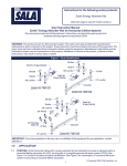
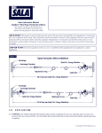
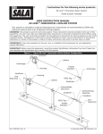
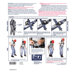
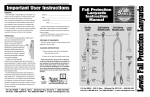
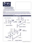
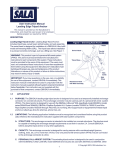
User Instruction Manual
Static Rope Grab
for 3/8 Inch Wire Rope
This manual is intended to be used as
part of an employee training program as
required by OSHA.
© Copyright 2003, DB Industries, Inc.
Figure 1 - 5000338 Static Rope Grab for Wire Rope
Detent Pin
Wedge/Handle Assembly
ID Label
Attachment
D-ring
Lifeline
WARNING: This product is part of a personal fall arrest or restraint system.
The user must follow the manufacturer’s instructions for each component of
the system. These instructions must be provided to the user of this
equipment. The user must read and understand these instructions before
using this equipment. These instructions must be followed for proper use
and maintenance of this equipment. Alterations or misuse of this equipment,
or failure to follow instructions, may result in serious injury or death.
IMPORTANT: If you have questions on the use, care, or suitability of this
equipment for your application, contact DBI/SALA.
IMPORTANT: Record the product identification information from the ID
label in the inspection and maintenance log in section 9.0 of this manual.
2
1.0
1.1
APPLICATIONS
PURPOSE: This rope grab is intended to be used as part of a
personal fall arrest system or restraint system. See Figure 2. The rope
grab provides a portable lanyard connection point on a wire rope
lifeline. Note: This rope grab is not designed to follow the worker. If
repositioning on your lifeline is required, you must manually reposition
the rope grab at the desired location.
Figure 2 - Applications
FALL ARREST: The rope grab is used as part of a personal fall arrest
system. Personal fall arrest systems typically include a rope grab,
lifeline, connecting subsystem (lanyard ), and full body harness.
Maximum permissible free fall is six feet.
RESTRAINT: The rope grab is used as part of a restraint system.
Restraint systems typically include a rope grab, lifeline, connecting
subsystem (lanyard), and full body harness. No vertical free fall is permitted.
1.2
LIMITATIONS: Consider the following application limitations before
using this equipment:
CAPACITY: This equipment is designed for use by persons with a
combined weight (clothing, tools, etc.) of no more than 310 lbs.
FREE FALL: Free fall must be limited to six feet. See subsystem
manufacturer’s instructions for more information.
FALL CLEARANCE: There must be sufficient clearance below the
worker to arrest a fall before striking the lower level or obstruction. See
section 3.0 for required clearance information.
3
SWING FALLS: See Figure 3. Swing falls occur when the anchorage
point is not directly overhead. The force of striking an object in a swing
fall may cause serious injury or death. Minimize swing falls by working
as directly below the anchorage point as possible. Do not permit a
swing fall if injury could occur. Swing falls will significantly increase
the clearance required when a self retracting lifeline or other variable
length connecting subsystem is used. If a swing fall situation exists in
your application, contact DBI/SALA before proceeding.
Figure 3 - Swing Fall Hazard
ENVIRONMENTAL
HAZARDS: Use of this
equipment in areas where
environmental hazards exist
may require additional
precautions to reduce the
possibility of injury to the user
or damage to the equipment.
Hazards may include, but are
not limited to: high heat,
caustic chemicals, corrosive
environments, high voltage
power lines, explosive or toxic
gases, moving machinery, or
sharp edges.
COMPATIBILITY: The rope
grab must be used with
components and subsystems that meet the requirements specified in
section 2.0.
LANYARD LENGTH: The lanyard length must be limited to four feet or less.
TRAINING: This equipment is intended to be used by persons trained
in its application and use.
1.3
2.0
2.1
APPLICABLE STANDARDS: Refer to applicable local, state, and
federal requirements governing this equipment for more information
on rope grabs and associated system components, including OSHA
1910.66, appendix C.
SYSTEM REQUIREMENTS
COMPATIBILITY OF COMPONENTS AND SUBSYSTEMS: This rope
grab is designed for use with DBI/SALA approved components and
subsystems only. Substitutions or replacements made with nonapproved components or subsystems may jeopardize compatibility of
4
equipment and may effect the safety and reliability of the complete
system. If you have questions regarding compatibility of components
or subsystems, contact DBI/SALA.
2.2
COMPATIBILITY OF CONNECTORS: Connectors are considered to
be compatible with connecting elements when they have been
designed to work together in such a way that their sizes and shapes
do not cause their gate mechanisms to inadvertently open regardless
of how they become oriented. Contact DBI/SALA if you have any
questions about compatibility.
Connectors (hooks, carabiners, and D-rings) must be capable of
supporting at least 5,000 lbs. (22kN). Connectors must be compatible
with the anchorage or other system components. Do not use
equipment that is not compatible. Non-compatible connectors may
unintentionally disengage. See Figure 4. Connectors must be
compatible in size, shape, and strength. Self locking snap hooks and
carabiners are required by ANSI Z359.1 and OSHA.
Figure 4 - Unintentional Disengagement (Roll-out)
If the connecting element that a snap hook (shown) or carabiner attaches to is
undersized or irregular in shape, a situation could occur where the connecting
element applies a force to the gate of the snap hook or carabiner. This force may
cause the gate (of either a self-locking or a non-locking snap hook) to open,
allowing the snap hook or carabiner to disengage from the connecting point.
Small ring or other
non-compatibly
shaped element
1. Force is applied to
the snap hook.
2.3
2. The gate presses against
the connecting ring.
3. The gate opens
allowing the snap
hook to slip off.
MAKING CONNECTIONS: Only use self-locking snap hooks and
carabiners with this equipment. Only use connectors that are suitable
to each application. Ensure all connections are compatible in size,
shape and strength. Do not use equipment that is not compatible.
Ensure all connectors are fully closed and locked.
5
DBI/SALA connectors (snap hooks and carabiners) are designed to be
used only as specified in each product’s user’s instructions. See
Figure 5 for inappropriate connections. DBI/SALA snap hooks and
carabiners should not be connected:
A. To a D-ring to which another connector is attached.
B. In a manner that would result in a load on the gate.
NOTE: Large throat opening snap hooks should not be connected to
standard size D-rings or similar objects which will result in a load on the gate
if the hook or D-ring twists or rotates. Large throat snap hooks are designed
for use on fixed structural elements such as rebar or cross members that are
not shaped in a way that can capture the gate of the hook.
C. In a false engagement, where features that protrude from the snap
hook or carabiner catch on the anchor and without visual
confirmation seems to be fully engaged to the anchor point.
D. To each other.
E. Directly to webbing or rope lanyard or tie-back (unless the
manufacturer’s instructions for both the lanyard and connector
specifically allow such a connection).
F.
To any object which is shaped or dimensioned such that the snap
hook or carabiner will not close and lock, or that roll-out could occur.
Figure 5 - Inappropriate Connections
6
2.4
ANCHORAGE STRENGTH: The anchorage strength required is
dependent upon the application:
FALL ARREST: From OSHA 1910.66 and 1926.500: Anchorages used
for attachment of a personal fall arrest system shall be independent of
any anchorage being used to support or suspend platforms, and be
capable of supporting at least 5,000 lbs. per user attached, or be
designed, installed, and used as part of a complete personal fall arrest
system which maintains a safety factor of at least two, and is
supervised by a qualified person.
RESTRAINT: Anchorages must be capable of supporting a minimum
of 3,000 lbs. per system attached to the anchorage.
WARNING: Restraint anchorages may only be used where there is no
possible vertical free fall. Restraint anchorages do not have sufficient
strength for fall arrest. Do not connect personal fall arrest systems to
restraint anchorages.
2.5
LIFELINES: DBI/SALA offers lifeline assemblies cut to your specified
length. If supplying your own lifeline, only use 3/8-inch diameter, 7x19,
galvanized steel aircraft cable, 14,400 lbs. minimum breaking strength,
per military specification MIL-W-83420 or MIL-W-1511. Lifeline
assemblies must have a minimum breaking strength of 5,000 lbs.
WARNING: Lifelines used with this rope grab must meet the size,
construction, material properties, and specifications stated above.
2.6
LANYARD: The lanyard length must be limited to four feet or less. For
personal fall arrest systems, DBI/SALA recommends using an energy
absorbing lanyard with self locking snap hooks. The energy absorbing
lanyard must limit fall arrest forces to 1,800 lbs. or less. Lanyards
labeled with ANSI A10.14, Type II, must not be used for fall arrest
applications. All lanyards must have a minimum breaking strength of
5,000 lbs.
2.7
BODY SUPPORT: For fall arrest applications, a full body harness
must be used. Although DBI/SALA does not recommend it’s use, a
body belt may be used for restraint applications.
3.0
OPERATION AND USE
WARNING: Do not alter or intentionally misuse this equipment. Consult DBI/
SALA when using this equipment in combination with components or
subsystems other than those described in this manual. Some subsystem and
component combinations may interfere with the operation of this equipment.
7
WARNING: Consult your doctor if there is reason to doubt your fitness to
safely absorb the shock from a fall arrest. Age and fitness seriously affect a
worker's ability to withstand falls. Pregnant women or minors must not use
DBI/SALA self retracting lifelines.
3.1
BEFORE EACH USE carefully inspect the rope grab according to
section 5.0.
3.2
PLAN your system before using this equipment. Consider all factors
that will affect your safety during use of this equipment. Consider the
following points when planning your system:
ANCHORAGE: Select a rigid anchorage point that is capable of
sustaining the required loads. See section 2.4. Carefully select the
anchorage location to minimize free fall and swing fall hazards. For
personal fall arrest systems, OSHA requires that the anchorage be
independent of the means suspending or supporting the user. For
restraint systems, the anchorage must be located such that no
vertical free fall is possible.
FREE FALL: Never work above your anchorage point. Position the
rope grab as far up the lifeline as possible to limit your free fall.
Personal fall arrest systems must be rigged to limit free fall distance
to six feet. Restraint systems must be rigged such that there is no
possible vertical free fall.
FALL ARREST FORCES: The personal fall arrest system must limit
fall arrest forces to 1,800 lbs. or less.
FALL CLEARANCE: There must be sufficient clearance in your fall
path to prevent striking an object or the lower level in the event of a
fall. The amount of clearance required is dependent upon the
application. See Figure 6 to estimate your required fall clearance.
WARNING: Ensure the design of your worksite and your working location
will allow the rope grab to remain locked on the lifeline when a fall occurs.
When a fall occurs, the lanyard must pull the attachment D-ring on the
rope grab down to lock the rope grab onto the lifeline.
SHARP EDGES: Avoid working where parts of the system will be in
contact with, or abrade against unprotected sharp edges.
SLOPED ROOF: When using this rope grab on a sloped roof, access
to roof edges and corners must be limited with guardrails, warning
lines, or monitors. Keep your lanyard length as short as possible.
8
Figure 6 - Clearance Requirements
GENERAL USE CONSIDERATIONS: Avoid working where your
lifeline may cross or tangle with that of another worker. Do not allow
your lanyard to pass under your arms or between your feet. Do not
clamp, tie, or otherwise prevent the rope grab from locking.
WARNING: The rope grab handle must not be prevented from locking onto
the lifeline by interference from objects, or be held open by hand when in
use. Failure to heed this warning may result in serious injury or death.
AFTER A FALL: Components which have been subjected to the
forces of arresting a fall must be removed from service and destroyed.
RESCUE: The employer must have a rescue plan in place when using
this equipment. The employer must have the ability to perform a
rescue quickly and safely.
9
3.3
MAKING CONNECTIONS:
ATTACHING THE ROPE GRAB TO THE LIFELINE:
Step 1
Step 1.
Up Arrow
Hold the rope grab in the up position,
as indicated by an arrow stamped on
the rope grab body.
Step 2
Remove Detent
Pins
Step 2.
Open the rope grab by
pressing the button on
both detent pins and
pulling the detent pins out
of the rope grab.
Step 3. Place the rope
grab body
around the
lifeline,
ensuring the
stamped arrow
is pointing up.
Install the
upper detent
pin.
Step 3
Place Rope Grab
around Lifeline
Step 4.
Install upper
Detent Pin
Install the wedge/
handle assembly
into the rope grab
by positioning the
slot in the wedge
around the upper
detent pin and
against the
lifeline.
Step 4
Place slot in Wedge
around upper Detent Pin
10
Step 5.
Rotate the bottom end of the wedge/handle assembly into
the rope grab until the hole in the handle aligns with the
lower hole in the rope grab body. Install the lower detent pin.
Step 5
Install lower
Detent Pin
Align hole in Handle
with hole in Body
Step 6.
Ensure the detent pins are securely locked. Check the
locking action by lifting the handle up and releasing. The
rope grab must lock onto the lifeline. If the rope grab does
not securely lock on the lifeline, repeat steps 1 through 5.
Do not use if the rope grab will not operate correctly.
CONNECTING THE LANYARD TO THE BODY SUPPORT: See Figure 7
Attach your lanyard to the rope grab D-ring. When using an energy
absorbing lanyard, the pack end of the lanyard is attached to the back
D-ring on your body harness. When using a body belt (for restraint
applications only) connect the restraint lanyard to the D-ring on your
body belt. Ensure all connections are compatible. See lanyard and
body support manufacturer’s instructions for more information.
3.4
Figure 7 - Connection
POSITIONING THE ROPE
GRAB ON THE LIFELINE:
This rope grab is designed to
remain in place on the lifeline.
To reposition the rope grab on
the lifeline, follow these steps:
Step 1.
Lift the rope grab
handle up to release
it from its current
position.
11
Step 2.
Raise or lower the rope grab to the new position. Position
the rope grab at or above your back D-ring to minimize free
fall distance.
Step 3.
To check the locking action of the rope grab, lift up the
handle and release. The rope grab must lock onto the
cable. If the rope grab does not operate correctly, repeat
attachment steps listed in section 3.3.
WARNING: Rope grab attachment and positioning procedures must be
followed. Improper attachment may cause the rope grab to slip or unlock
from the lifeline, which may result in serious injury or death.
4.0
4.1
TRAINING
It is the responsibility of all users of this equipment to understand
these instructions, and to be trained in the correct installation, use,
and maintenance of this equipment. These individuals must be aware
of the consequences of improper installation or use of this equipment.
This user manual is not a substitute for a comprehensive training
program. Training must be provided on a periodic basis to ensure
proficiency of the users.
IMPORTANT: Training must be conducted without exposing the trainee to a
fall hazard. Training should be repeated on a periodic basis.
5.0
5.1
INSPECTION
FREQUENCY:
• Before Each Use: Inspect the rope grab according to the steps
listed in section 5.2 and 5.3.
• Annually: The rope grab must be inspected by a competent
person other than the user at least annually. See sections 5.2
and 5.3 for inspection steps.
WARNING: If the rope grab has been subjected to fall arrest or impact
forces it must be removed from service and destroyed.
IMPORTANT: Extreme working conditions (harsh environments,
prolonged use) may require increasing the frequency of inspections.
5.2
INSPECTION:
Step 1.
Inspect the detent pins. The button should spring back when
12
pushed down. The pins should slide easily through the rope
grab body and wedge/handle assembly.
5.3
Step 2.
Inspect the function of the wedge/handle assembly. The
handle should move freely, with no sticking or binding. The
wedge must engage and lock onto the lifeline. The handle
spring must be in place and undamaged.
Step 3.
Inspect the lanyard attachment D-ring. The D-ring must be
free of corrosion, cracks, or other deformities. The bracket
and pin holding the D-ring must be undamaged.
Step 4.
Inspect the rope grab body. The rope grab body must be
free of wear, corrosion, cracks, or other deformities.
Step 5.
All labels and markings on the rope grab must be present
and fully legible. See section 8.0.
Step 6.
Inspect the lifeline according to the manufacturer’s
instructions.
If inspection reveals an unsafe or defective condition, remove the rope
grab from service and destroy it, or contact an authorized service
center for repair.
IMPORTANT: Do not alter or attempt to repair the rope grab. Do not make
substitutions for the rope grab parts. Repairs may only be performed by
an authorized service center.
6.0
MAINTENANCE, SERVICING, STORAGE
6.1
Periodically clean the rope grab using water and mild detergent.
Clean the label as required.
6.2
Replacement parts and additional maintenance and servicing
procedures must be completed by an authorized service center. An
authorization and return number must be issued by DBI/SALA.
6.3
Clean and store system components according to the manufacturer’s
instructions.
6.4
Store the rope grab in a clean and dry environment out of direct
sunlight. Avoid areas with chemical vapors. Inspect the rope grab after
extended storage.
13
7.0
7.1
SPECIFICATIONS
SPECIFICATIONS:
• Weight: 2.25 lbs.
• Overall Dimensions (including detent pins): 10.5x2.5x5.5
inches.
• Materials: Stainless steel.
• Patent Numbers: U.S. patent numbers: 3,979,797; 4,071,926;
Canadian patent numbers: 1,037,000; 1,052,340; 1,102,288.
7.2
PERFORMANCE DATA:
• Arrest Force: Designed for 1,800 lbs. maximum arresting force.
• Maximum Capacity: 310 lbs.
• Applicable Standards: OSHA 1910.66, appendix C.
8.0
LABELING
These labels and markings must be present and fully legible:
Label and Markings
(Rope Grab shown with
Detent Pins removed for clarity)
14
9.0
INSPECTION AND MAINTENANCE LOG
SERIAL NUMBER: ___________________________________________
MODEL NUMBER: ___________________________________________
DATE PURCHASED: _________________________________________
INSPECTION DATE
INSPECTION ITEMS
NOTED
CORRECTIVE ACTION
Approved By:
Approved By:
Approved By:
Approved By:
Approved By:
Approved By:
Approved By:
Approved By:
Approved By:
Approved By:
Approved By:
Approved By:
15
MAINTENANCE
PERFORMED
USA
Canada
3965 Pepin Avenue
Red Wing, MN 55066-1837
Toll Free: 800-328-6146
Phone: (651) 388-8282
Fax: (651) 388-5065
www.salagroup.com
260 Export Boulevard
Mississauga, Ontario L5S 1Y9
Toll Free: 800-387-7484
Phone: (905) 795-9333
Fax: (905) 795-8777
www.salagroup.com
This instruction manual is available for download at www.salagroup.com.
I S O
9001
Certificate No. FM 39709
Form: 5906265
Rev: D