1
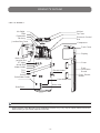
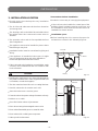
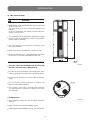
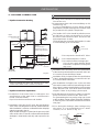
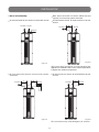
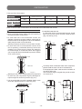
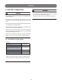
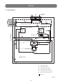
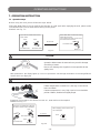
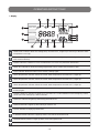
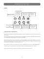
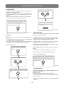
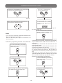
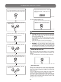
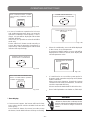
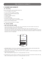
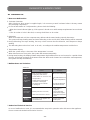
WATER HEATER
INSTALLATION & USER'S MANUAL
Model
HWMI 300 A
WARNING!
PLEASE READ CAREFULLY THIS MANUAL BEFORE INSTALLING THE WATER HEATER
-1-
TERMAL S.R.L. Via della Salute, 14 -- 40132 -- Bologna -- ITALY
EN
IT
EUROPEAN REGULATIONS CONFORMITY FOR THE MODELS:
Water Heater:
HWMI 300 A
CE
All the products are in conformity with the following European provision:
- Low Voltage Directive 73/23/EEC
- Low Voltage Directive 2006/95/EC
- Electromagnetic CompatibilitY 89/336/EEC
- Electromagnetic CompatibilitY 2004/108/EC
ROHS
The products are fulfilled with the requirements in the directive 2002/95/EEC of the
European parliament and of the council on the Restriction of the use of Certain Haz.
ardous Substances in Electrical and Electronic Equipment (EU RoHS Directive)
WEEE
In accordance with the directive 2002/96/CE of the European parliament,
herewith we inform the consumer about the disposal requirements of the
electrical and electronic products.
DISPOSAL REQUIREMENTS:
Your Water Heater is marked with this symbol.
This means that electrical and electronic products
shall not be mixed with unsorted household waste.
Do not try to dismantle the system yourself: the dismantling of this kind of system, treatment of the
refrigerant, of oil and of other part must be done
by a qualified installer in accordance with relevant
local and national legislation. Water Heater must be
treated at a specialized treatment facility for re-use, recycling and recovery.
By ensuring this product is disposed of correctly, you will help to prevent
potential negative consequences for the environment and human health.
Please contact the installer or local authority for more information.
-2-
! WARNING
This Unit is required reliable earthing
before usage, otherwise might cause
death or injury.
Please ask Authorized Technical Service
for reliable earthing connection.
Your safety is the most important thing we concerned!
-3-
Table of Contents
PRODUCT'S OUTLINE............................................................................................................. 5
PRECAUTIONS & ACCESSORIES.......................................................................................... 6
INSTALLATION......................................................................................................................... 8
WIRING................................................................................................................................... 13
OPERATING INSTRUCTIONS................................................................................................ 15
TRIAL RUNNING & CAPABILITY............................................................................................ 22
MAINTENANCE...................................................................................................................... 24
DIAGNOSTIC & ERROR CODES........................................................................................... 25
AUTOMATIC RESTART AFTER A BLACKOUT...................................................................... 27
-4-
PRODUCT'S OUTLINE
PARTS NAMES
Air Outlet
Air Inlet
Top Cover
Filter
Evaporator
Fan Assy
Junction Box Cover
Electronic Control
Box
Compressor
Front Cover
Display
Back Cover
Junction Box
PT Valve
Anode Rod
Water Outlet
Cover
Electric Heater
TCO
TOD
Solar Sensor
Solar Water Outlet
Front
Decorative
Board
Cover, Electric
Heater
Solar Water Inlet
Water Inlet
Drain Pipe
NOTE
All the pictures in this Manual are for explanation purpose only. They may be slightly different from the
Water Heater you purchased (depends on Model).
-5-
PRECAUTIONS & ACCESSORIES
WARNING
the Authorized Technical Service for installation
• Ask
of Water Heater Unit.
Improper installation may result in water leakage,
electric shock or fire.
1. PRECAUTIONS
To prevent injury to the User or other people and
property damage, the following instructions must be
followed. Incorrect operation due to ignoring of
instructions may cause harm or damage.
• Ask the Authorized Technical Service for the repair
and maintenanance.
Improper repair and maintenance may result in water
leakage, electric shock and fire.
• In order to avoid electric shock, fire or injury, if any
abnormality is detected - such as smell of fire - turn
off the power supply and call Authorized Technical
Service for instructions.
The safety precautions listed below are divided in two
categories: “WARNING” and “CAUTION”.
In both cases, safety instructions are very important and
must be followed carefully.
• Never use the wire and fuse with wrong rated current.
Use of wrong wire or fuse may cause the Unit to break
down or a fire.
• Do not insert fingers, rods or other objects into the
air inlet or outlet.
When the fan is rotating at high speed, it will cause
injury.
• Never use a flammable spray such as hair spray,
lacquer paint near the Unit.
It may cause a fire.
WARNING
Failure to observe a warning may result in
death or serious injury.
• Never touch the air outlet or the horizontal blades
while the swing flaps is in operation.
Fingers may be caught or the Unit may break down.
• Never put any objects into the air inlet or outlet.
Objects touching the fan which rotates at high speed
can be dangerous.
CAUTION
Failure to observe a caution may result in
injury or damage to the equipment.
• The appliance must be installed in accordance with
national wiring regulations.
• The appliance must not be used by children without
supervision.
• If the supply cord is damaged, it must be replaced by
the Manufacturer or by the Authorized Technical Service,
in order to avoid the hazard of electric shocks.
• An all-pole disconnection device which has at least
3mm separation distance between its contacts shall
be incorporated in the fixed wiring, according to
national rules.
WARNING
DISPOSAL: Do not dispose this Product as unsorted
• The Water Heater Unit must be earthed effectively. • municipal waste. Collection of such waste separately
• A creepage breaker must be installed near the power
supply.
• Do not tear off the labels on the Units for the purpose
of warning/reminding and warranty.
for special treatment is necessary.
Do not dispose of electrical appliances as unsorted
municipal waste: use separate collection facilities.
Please contact your local government for information
regarding systems available.
• If electrical appliances are disposed of in landfills
or dumps, hazardous substances can leak into the
groundwater and get into the food chain, damaging
your health and well-being.
-6-
PRECAUTIONS & ACCESSORIES
2. ACCESSORIES
CAUTION
•
•
•
The earth pole of terminal must be earthed, and the
rated current must be more than 10A. Make sure
that power supply terminal and power supply plug
are dry enough and have a good connection.
Method: Turn on power supply, run the Unit for half
an hour then turn it off and check whether the power
supply plug is hot or not. If it is hot (more than 50°C)
please change it with a new and eligible one, or it may
result in a electric shock or fire.
Table 2-1
Do not use the Water Heater Unit for other purposes
different from that it has been conceived.
Before cleaning, be sure to stop the operation and
turn the breaker off or pull out the power cord.
Otherwise, an electric shock and injury may be
caused.
•
Please pay attention because water too much hot
(more than 50°C) inside the Water Heater may cause
serious injuries.
•
In order to avoid injuries, do not remove the fan guard
on the Outdoor Unit.
•
Do not operate the Water Heater Unit with wet hands.
An electric shock may be caused.
•
The installation height of power supply should be
over 1.8m, to prevent any sprinkling of water from
reaching the Unit.
•
In the water inlet side, the One Way valve must be
installed.
•
It is normal if some water drops from the hole of PT
valve during operation. In case of a great amount of
water, please contact the Authorized Technical Service
for instructions.
After a long term use, check the Unit stand and fittings.
If damaged, the Unit may fall and result in injury.
Arrange the drain hose to ensure smooth drainpipe.
Improper drainpipe may cause wetting of the building,
furniture, etc.
Do not touch the inner parts of the controller.
Do not remove the frontal panel. Some parts inside are
dangerous to touch, and this may cause malfunctions
to the appliance.
Do not turn off the power supply.
System will stop or restart heating automatically. A
continuous power supply for water heating is necessary,
except when repairing and maintenance are carried
out.
-7-
Accessory name
Q.ty Sharp
Purpose
User & Installation
Manual
1
Instructions for installation
& use (this Manual)
Y-shaped filter
1
To filtrate inlet water
One Way valve
1
Prevent water from
flowing back
Adaptor
1
Drain condensate water
INSTALLATION
3. INSTALLATION LOCATION
• Enough space must be kept for easy installation
and maintenance.
• The air inlet and outlet must be free from obstacles
• Precautions before installation
• Decide the correct way of conveying the equipment.
• If the Unit has to be installed in a metal part of the
building, electric insulation must be carried out, and
the installation must meet the relevant technical
standards for electric devices.
and strong wind.
• The bearing surface should be flat and able to bear
the weight of the Unit. It must not increase noise or
vibration.
• The operation noise and air flow expelled shall not
• Installation space
• Before installing the Unit, reserve the space for
affect neighbours.
maintenance shown in the following Figures.
• The appliance must not be installed in places where
flammable gas may leak.
• Installation location must be convenient for piping and
Air outlet
wiring.
•
If the appliance is installed in indoor space, it might
cause a temperature drop and noise disturbance.
Please take preventive measures for this.
≥600mm
≥600mm
≥600mm
Barrier
• If the Unit needs to be installed on a metal holder, make
sure they are insulated well and in accordance with
local standards.
Air inlet
CAUTION
Display
Fig. 3-1
• Installing the equipment in any of the following places
may lead to malfunctions of the equipment itself (if it
is inevitable, consult the Supplier).
•
• Seaside, where the air contains much salt.
• Sites where there are corrosive gases.
≥800mm
The site contains mineral oils such as cutting lubricant.
≥600mm
≥600mm
• Factories where the power voltage fluctuates seriously.
• Inside a car or cabin.
• Place like kitchen where oil permeates.
• Place where strong electromagnetic waves exist.
• Place where flammable gases or materials exist.
• Place where acid or alkali gases evaporate.
• Other special environments.
Fig. 3-2
-8-
INSTALLATION
4. INSTALLATION
WARNING
• Water Heater Units must be installed only by Authorized
Technical Service.
The User must never try to install the appliance by
himself.
Incorrect installation may result in water leakages,
electric shock or fire.
• The equiment must be installed far from direct sunlight
and from other heat appliances. If this is not possible,
please install a covering.
• The Unit must be securely fixed, in order to avoid
noise and vibration.
• Make sure there is no obstacle around the Unit.
• In places where there is strong wind like seashore,
fix the Unit in a location protected from the Unit.
Fig. 4-1
• Carry the Unit to the installation site by observing
the rules and limits set by Manufacturer
• In order to avoid scratching or deforming the Unit’s
surface, apply guard boards to the contacting surface.
• Avoid contact of fingers or of other objects with the
vanes.
• Don’t incline the Unit more than 45° in moving, and
Ø 650
keep it vertical when installing.
• This system is very heavy: it needs to be carried by
2 or more persons, otherwise it might cause injury
and damage.
• Install the Unit
• The circulating air for every Unit should be more than
700m /h.
3
• Make sure there is enough installation space.
• Outline dimensional drawings: see Fig. 4-1 and Fig. 4-2.
-9-
Fig. 4-2
INSTALLATION
5. PIPELINE CONNECTION
NOTE
• A safety valve should be installed at the water
• Pipeline Connection Drawing
•
• The handle of PT Valve should be pulled out once
Upper
Condensate Outlet
Lower Condensate
Outlet
inlet of the Unit.
Arrange water pipes and connected fittings as it is
shown in Fig. 5-1.
In case of installation in a place where outside
temperature is below freezing point, insulation must
be provided for all hydraulic components.
PT Valve
User
Water
Outlet
Anode rod
per half year, to make sure that there is no jam of
the valve. Please beware of burn, because of the
high temperature of water.
The drainage pipe should be well installed, in order
to avoid freezing up in cold weather.
Notice:
the mixer tap is
required on the hot
water usage terminal
Handle
Drainage pipe
• Do not press the handle of PT Valve.
• Do not dismantle the PT Valve.
• Do not block off the Drainage pipe.
Solar sensor
Solar water outlet
Solar water inlet
Y-shaped Filter Tap Water
Drainpipe
Water
Inlet
EXPLOSION
One Way Valve Ball Valve
If you do not comply with the above
instructions, explosions and injuries
may occur.
• Installation of the One Way Valve: the specifications
Barrel-drain
of the One Way Valve thread in accessories is RC3/4”.
It is used to prevent backflow of water.
Fig. 5-1
• Installation of the Y-shaped Filter: the specifications
of the Y-shaped filter thread in accessories is RC3/4”.
It is used to filtrate inlet water.
CAUTION
When installing the main Unit, please set a drain
valve at the drain orifice of the Unit itself.
• After installation of all pipes, turn on the cool water
inlet and hot water outlet and start effusing the tank.
When there is water normally flowing out from water
outlet, the tank is full. Turn off all valves and check
all pipes. If there is any leakage, please repair.
• Pipeline Connection Explanation
the inlet pressure is less than 0.15MPa, a pressure
• Installation of the water inlet or outlet pipes: the • Ifpump
should be installed at the water inlet.
specifications of the water inlet or outlet thread is
RC3/4” (internal thread).
Pipes must be heat-resistant and durable.
• Installation of the pipe for PT valve: the specifications
of the valve conncting thread is RC3/4” (internal thread).
After installation, it must be confirmed that the drainpipe
outlet is exposed in the air.
When flexible drainpipe is jointed to the pressure relief
orifice of this valve, it must be confirmed that the flexible
drainpipe is downwards vertically and exposed in the
air.
For guaranteeing the long safety using age of tank
at the condition of water supply higher than 0.65MPa,
a reducing valve should be mounted at the water
inlet pipe.
• Since during the drainage, water leakages may
take place, it is recommended to use a water
collector, as it is shown in Fig. 5-2.
Water Heater
Max. 22mm
50mm larger
than the diameter
of Water Heater
- 10 -
Fig. 5-2
INSTALLATION
• Duct Connection Way
• Note: Upon connection of canvas, airflow rate and
capacity in heat pump system decrease.
• Air inlet and outlet do not need to connect with canvas. • Air inlet without canvas, air outlet connect to canvas:
A≤10m.
Air Outlet
Air Inlet
Air Outlet
Air Inlet
Ø190mm
Fig. 5-5
Fig. 5-3
This type of duct connection is recommended if the
appliance is installed inside a room where temperature
is higher than outdoor temperature.
• Air inlet and outlet need to connect with canvas: • Air inlet connect to canvas, air outlet without canvas:
A+B≤10m.
Air Inlet
Air Outlet
Air Inlet
Ø190mm
Air Outlet
A≤10m.
Fig. 5-4
Fig. 5-6
This connection way is advantageous in summer.
- 11 -
INSTALLATION
• Canvas Duct Description
Dimension(mm)
Straight-line
pressure drop (Pa/m)
Ø190
≤2
≤10
≤2
≤5
Rectangle canvas duct
190x190
≤2
≤10
≤2
≤5
Other shaped
canvas duct
Refer to above data
Canvas Duct
Round canvas duct
Straight-line length (m) Bent pressure drop (Pa) Bent’s qty.
Note: In case of need, canvas duct to be connected at air outlet better than at inlet.
• Upon connected canvas, airflow rate and capacity in
• Install filter inside the Unit.
In case main Unit is connected with canvas, install
filter at the air inlet of duct and then install the duct
(Fig. 5-9 and Fig. 5-10).
heat pump system will decrease.
• In case main Unit is connected with canvas, the
diameter of the duct must be ≥190mm, total length of
the ducts must not be longer than 10m or the maximum
static pressure must not exceed 50Pa.
Warning! The duct must have no more than 5 bends.
Outlet
ØD
Inlet
≥2.5D
NOTE
Filter
• In case main Unit is connected with canvas, when
Filter
Unit is operating, condensate dew may form at the
outside of air outlet canvas. Please pay attention
to the discharge of condensate water. We suggest
you to wrap the thermal insulated layer at the outside
of air outlet canvas.
Rain
Fig. 5-9
Main Unit
Fig. 5-10
• To fluently drain condensate water from evaporator,
please install the main Unit at a horizontal floor.
If the equipment is tilted, make sure the inclination is
on side of drain vent.
The inclination angle as regards the ground must be
no more than 2°.
Fig. 5-7
• Warning! If case of rain entering internal components
of main Unit, the components might be damaged or
injuries might be caused to persons (Fig. 5-7).
• It is recommended to provide a weather shed in case
ducts are exposed to rain or snow (Fig. 5-8).
Drain
Drain
Rain
Weather shed
Fig. 5-11
Fig. 5-8
- 12 -
Fig. 5-12
WIRING
6. ELECTRIC CONNECTION
WARNING
CAUTION
• The power supply for the Unit must correspond to the
rated voltage.
• Earthing must be included in the power circuit. And
it must be connected with the effective external ground
wire.
• The wiring must be performed by Authorized Technicians
according to the circuit diagram.
• Set the electric leakage protector according to the
current electric technical standards.
• The power cord and the signal cord must be properly
laid out, without mutual interference or contacting
the connection pipe or valve.
• After wire connection is finished, check it again and
make sure the correctness before supplying power.
6.1 Specifications of Power Supply
Table 6-1
Model Name
HWMI 300A
Power Supply
220-240V~50Hz
Min. Diameter of Power Supply Line
(mm2)
2.5
Earth wire (mm2)
2.5
Manual Switch(A) Capacity/Fuse
15/5
Creepage Breaker
30 mA ≤ 0.1sec
Please choose the power cable according to the
above table and according to local electric standard.
- 13 -
For safety, a Creepage Breaker must be installed
on the Unit near the power supply.
Moreover, the Unit must be effectively earthed.
WIRING
6.2 Wiring Diagram
220-240V~
50 Hz
Main Control Board
Compressor
Control Panel
Electric Heater
Pressure Switch
Compressor
Water Tank
T3:
Tube Temp. Sensor
T4:
Ambient temp. Sensor
T5L: Tank Temp. Sensor (lower)
T5U: Tank Temp. Sensor (upper)
TP:
Discharge Temp. Sensor (upper)
TH:
Return air temperature sensor
Earthing
Fig. 6-1
- 14 -
OPERATING INSTRUCTIONS
7. OPERATION INSTRUCTION
7.1 Operation steps
Before using this Unit, please follow the steps below.
Filling the Water Tank: if Unit is used for the first time or used again after emptying the tank, please make
sure that the tank is full of water before turning on the power.
Method: see Fig. 7-1.
When water flows out from the water
outlet, the tank is full.
Turn off the hot water outlet valve
and water flow is finished.
Open the cool water inlet and hot
water outlet
Open
Open
Water Flow
Close
Hot water outlet
Cool water inlet
Hot water outlet
Water out
Fig. 7-1
CAUTION
Operation without water in water tank may result in damage
of auxiliary e-heater.
Due to such damage, the Supplier is not responsible for the
quality issue.
After powered on, the display lights up. User can operate the Unit through the buttons for selecting different
modes which are displayed.
CAUTION
If water temperature exceeds 50°C, this may cause serious
burns and death.
If water temperature is very high, special care should be
paid to children, disabled and aged people.
Emptying: if Unit needs to be cleaned, moved, etc., water tank must be emptied.
Method: see Fig. 7-2.
Close the cool water inlet, open the
hot water outlet and open drainpipe.
After emptying, please replace the
nut of drainpipe.
Open
Emptying
Close
Close
Hot water outlet
Drainpipe
Open
Cool water inlet
Drainpipe
Fig. 7-2
- 15 -
OPERATING INSTRUCTIONS
•
Display
ECONOMY MODE
HIGH TEMP
FILL WATER
LOCK
HYBRID MODE
E-HEATER MODE
TEMP-SET
ALARM
OUTLET TEMP
TIME ON
TIME OFF
TIMER
CONFLICT
HIGH TEMP indicator: When the setting temp. exceeds 50°C, it lights up to remind you that the outlet
temperature is too high.
FILL WATER indicator: When the power supply is turned on, it lights up to remind you that the water
tank must be filled up.
ALARM indicator: It flashes in case of malfunction or in case of a protection intervention.
TEMP SET indicator: It shows the setting temperature or Error Codes and Protection Codes.
LOCK indicator: When the Indoor Unit is locked, it always lights.
Water temperature indicator: When the actual water temperature exceeds 60°C, it lights up.
Water temperature indicator: When the actual water temperature exceeds 50°C, it lights up.
Water temperature indicator: When the actual water temperature exceeds 40°C, it lights up.
OUTLET TEMP indicator: It displays water temperature of the upper part of the tank, which can be used.
It always lights.
TIMER CONFLICT indicator: It lights up in case there is a conflict between Timer settings by control
panel and Timer settings by a wired controller.
TIME OFF indicator: It lights up when timing off mode is set.
TIME ON indicator: It lights up when timing on mode is set.
CLOCK indicator: It displays present time.
E-HEATER MODE indicator: It lights up when User sets the E-Heater mode.
HYBRID MODE indicator: It lights up when User sets Hybrid mode.
ECONOMY MODE indicator: It lights up when User sets Economy mode.
- 16 -
OPERATING INSTRUCTIONS
• Buttons
ON/OFF key, used to
turn the Unit on or off.
CLOCK key, used to
set time.
CANCEL key,
used to cancel
Timer and lock all
Unit’s keys
(LOCK function).
MODE key, used
to set different
operation modes.
ON\OFF
CANCEL
MODE
CLOCK
TIME
ON
TIME
OFF
TIME ON key,
used to set the ON timer
for automatic start
of Water Heater.
TIME OFF key,
used to set the OFF
timer for automatic
stop of Water Heater.
UP key, used to
add time or
temperature.
DOWN key, used to
decrease time or
temperature.
• Preparation before running the Unit
When you run the Unit for the first time, all the indicators on the Unit will light for 3 seconds, while the buzzer
will ring twice.
After no operation for 1 minute, all indicators will go out automatically except FILL WATER indicator (flashing)
and WATER TEMP indicator (lighting, it shows tank’s temperature).
When the tank is full, please press the ON/OFF key: the FILL WATER indicator will stop flashing and you can
set your desired operation modes. When setting is completed, please press ON/OFF key again and the
FILL WATER indicator will go out. And then run the Unit.
When the Unit is running, if no selection is carried out or no malfunction occurs for 20 seconds, the backlight of
the display will go out automatically except operation mode, outlet temperature and LOCK indicator.
If there is no operation for 1 minute, the Unit will lock automatically (LOCK function).
- 17 -
OPERATING INSTRUCTIONS
• LOCK/UNLOCK
Press the UP and DOWN keys,
you can adjust the hour.
In order to prevent wrong operation, a special lock
function has been designed.
If there is no operation for 1 minute, the Unit will be
locked automatically, and display shows the Lock
indicator.
When the Unit is locked, no keys can be operated.
To unlock Unit, please proceed as follows:
At the locking status of Display, long
press the CANCEL key to remove it.
LOCK indicator will blank out and all
keys can be used normally.
Press CLOCK key again or stop
operation for about 10 seconds,
flashing will stop and clock set
is successful.
CANCEL
Fig. 7-4
• Mode Selection
Fig. 7-3
Unit has three operation modes: Economy Mode, Hybrid
Mode and E-heater Mode.
• Clock Set
The clock is for a 24-hour system and the initial time
is 00:00.
To make a better use of this Unit, it is recommended
to set the time for accurate local time.
Every time Unit is disconnected, the clock will be reset
to 00:00 and it will need to be adjusted again.
Method for time set:
Press CLOCK key: the minute
digits of the clock start flashing
slowly.
CLOCK
ECONOMY Mode: The Unit heats water only by
compressor drive according to heat-pump principle.
Used when the ambient temperature is high.
HYBRID Mode: The Unit heats water not only by
compressor drive but also by electric heater.
Used when the ambient temperature is low or a large
amount of hot water is needed.
E-HEATER Mode: The Unit heats water only by electric
heater.
Used when the ambient temperature is very low.
By default, the Unit operates in HYBRID Mode.
To change operation mode:
Press the MODE key, operation mode will be
shifted among the three modes in a cycle,
meanwhile the corresponding indicator on
the display will light up. Select your desired
operation mode.
Press UP and DOWN key, you
can adjust minutes.
MODE
Fig. 7-5
Press the CLOCK key again, the minute
digits stop flashing while the hour digits
starts.
CLOCK
• Temperature Set
Temperature displayed is the water temperature in the
upper part of the tank.
Default is 55°C.
The Economy mode setting range is 38~60°C.
The Hybrid and E-heater mode setting mode setting
mode is 38~70°C.
In the following page, method for setting temperature
is shown.
- 18 -
OPERATING INSTRUCTIONS
Press the UP and DOWN key,
you can adjust the hour..
Press the UP and DOWN key, you can increase
or decrease the water temperature.
Fig. 7-6
Press the TIME ON key again
and wait about 10 sec., flashing
stops and ON TIMER set is
finished.
When the set temperature is higher than 50°C,
the HIGH TEMP indicator will light.
HIGH TEMP
Fig. 7-8
To cancel TIME ON:
Fig. 7-7
In the unlocked state, press the
CANCEL key for 1 sec. and the TIME
ON function will be cancelled.
• Timer
CANCEL
User can set up a time for automatic start/stop of the
Water Heater, by Timer function.
Time can be set by min. steps of 10 minutes, in a
24-hour system.
Method for programming automatic start (TIME ON):
Press the TIME ON key, the minute
digits of the clock on the display
start flashing slowly.
TIME
ON
Press the UP and DOWN key, you
can adjust the minutes.
Fig. 7-9
Programming the automatic start followed by automatic
stop of Water Heater (TIME ON and TIME OFF in
sequence):
User can set his desired time for automatic start and
stop of Water Heater.
When the start time is earlier than the stop time, the
Unit will run between the set time.
When the start time is later than the stop time (for
ex. start at 06:00, stop at 04:00), the Unit will run
between the start time today and the stop time next
day.
When User sets up the same time for start and stop,
the Water Heater will start according to the set start
time and will automatically stop after 10 minutes.
Method for setting TIME ON/TIME OFF:
Press the TIME ON key, the minute
digits of the clock on the display
start flashing slowly.
TIME
ON
Press the UP and DOWN key, you
can adjust minutes.
Press the TIME ON again, the minute digits
stop flashing and the hour digits start.
TIME
ON
- 19 -
OPERATING INSTRUCTIONS
Stop operation for about 10 sec., flashing
stops and TIME ON + TIME OFF set is
finished.
Press the TIME ON key again, the minute
digits stop flashing and the hour digits start.
TIME
ON
Fig. 7-10
To cancel TIME ON/OFF set:
In the unlocked state, press the
CANCEL key for 1 second, the TIME
ON/OFF function will be cancelled.
Press the UP and DOWN keys, you can
adjust the hour.
CANCEL
Fig. 7-11
NOTE
Press the TIME OFF key, the minute digits
on the display start flashing slowly.
•
TIME
OFF
•
•
•
Press the UP and DOWN keys, you can
adjust minutes.
Time ON and Time OFF cannot be set to the same
time. If they are the same, the stop time will delay
10 minutes automatically.
For example, Time ON and Time OFF set to
01:00 at the same time, stop time will be to 01:10
automatically.
Time OFF function cannot be used alone.
The key can be used only after set the Time ON.
Warning! In case of a blackout, when power supply
is restored, the Water Heater will automatically
restart with previous settings, but Timer settings will
be cancelled, so it is necessary to set Timer again.
• Power ON and Power OFF
Press the TIME OFF key again, the minute
digits stop flashing and the hour digits start.
After selecting the desired settings, press ON/OFF
button and the Water Heater will start according to the
settings.
To stop the appliance, press again ON/OFF button.
TIME
OFF
ON\OFF
Fig. 7-12
Press the UP and DOWN keys, you can
adjust the hour.
• Operation status
The LA error code from the screen of set Temperature
will appear and reminds User when ambient temperature
does not meet the operation conditions of heat pump
Unit (5~43°C).
User can switch the Economy mode to E-heater mode
to reach a higher volume of hot water if needed.
The Unit will return operation pre-status automatically
when the ambient temperature meets the operation
conditions of heat pump mode and the error LA will
disappear at the same time.
- 20 -
OPERATING INSTRUCTIONS
Error Code which means a conflict
with operating conditions of heat
pump
ALARM indicator flashes to
indicate that there is a malfunction
TEMP-SET
ALARM
Fig. 7-13
Press CANCEL key to stop
the buzzer.
• In case of continuous operation for 20 hours
and ambient temperature does not meet the
operation conditions of heat pump (-7~43°C
range), LA code will be displayed and ALARM
indicator will flash.
In this case, it is possible to select E-HEATER
mode only.
Please switch to E-heater mode manually to
ensure that normal operation of appliance is
restored (LA code will disappear and ALARM
indicator will stop flashing).
CANCEL
Fig. 7-16
•
If there is a malfunction, error code will be displayed
in the screen of set Temperature.
If you press CANCEL button, LA error code will be
displayed for another 1 minute, then display will
show temperature value.
ALARM indicator flashes to
indicate there is a malfunction
Visualizzazione del Codice
di Errore.
ALARM
TEMP-SET
Fig. 7-14
Fig. 7-17
Error Code which indicates that
there is a conflict with the operation
condition of heat pump
•
If a malfunction occurs while system works in
Economy mode, operation may keep on if E/heater
mode is selected.
When some error happens, though the system
could be used in some circumstances, it could not
reach the expected efficiency.
Please contact the Authorized Technical Service.
•
Error Code Explanation: see further on, Table 10/2.
TEMP-SET
Fig. 7-15
WARNING
• Error Display
• If some errors happen, the buzzer will buzz 3 times
every other minute and the ALARM indicator will
flash quickly.
Press CANCEL button for several seconds to stop
the buzzer, but ALARM indicator will keep on flashing.
- 21 -
• Whatever intervention on Water Heater
must be carried out by Authorized Technical
Service, as there is danger of electric
shocks.
TRIAL RUNNING & CAPABILITY
8. RUNNING AND CAPABILITY
8.1 Trial Running
Before running, please check the following items first:
•
•
•
•
•
•
•
•
•
•
•
Correct installation of the system;
Correct connection of pipeline and wiring;
Leakage of the refrigerant pipeline tested;
Efficient drainpipe;
Complete insulation protection;
Correct earthing;
Correct power supply;
No obstacle outside the air inlet and outlet;
No air in the water pipeline and all valves opened;
Effective electric leakage protector;
Sufficient inlet water pressure ( ≥ 0.15MPa)
8.2 Operating Capability
• Water Heater Operating Capability
Three heating elements are included in the Unit: one heat pump, one electric heater and a solar coil.
All these three heating elements do not work together.
This Unit has two temperature sensors, which are installed at the upper 1/4 and bottom 1/2 of Unit.
The upper sensor tests the water temperature in the upper part of Unit (shown by display); the bottom
sensor tests the water temperature in the bottom part of Unit and controls the ON/OFF of Unit itself (the
temperature value is not displayed).
Outlet
Upper sensor
Bottom sensor
Electric heater
Tank coil
Inlet
•
ECONOMY Mode: In this mode, according to the water temperature setting, only heat pump works.
(Water outlet temperature range 38~60°C, running temperature -7~43°C).
•
HYBRID Mode: In this mode, the system will adjust the working capabiities of e-heater and heat pump according
to the tank water temperature.
(Water outlet temperature range 38~70°C, running temperature -30~43°C).
•
E-HEATER Mode: In this mode, the compressor and the fan motor will not run but the e-heater works only.
(Water outlet temperature range 38~70°C, running temperature -30~43°C).
- 22 -
TRIAL RUNNING & CAPABILITY
• In the following circumstances, self-protection starts:
NOTE
1) Air inlet or outlet is obstacled;
2) The evaporation is covered with too much dust;
In E-Heater mode, only half tank of water, i.e. 150L,
could be heated every time.
• Defrosting during Water-heating
• In the Economy Mode and Hybrid Mode, if the
3) Incorrect power supply (exceeding the range of
207~253V).
NOTE
evaporation frosts in a cold circumstance, the system
will defrost automatically to keep effective performance
(3~10min.).
In case of intervention of self-protection, disconnect
the appliance and restart it after malfunction has
been solved.
• Ambient Temperature
• Water Temperature Display
• The system’s operation temp. is within -30°C~43°C
and below are the operation temperature for each
• The temperature on the display is the water
mode.
temperature in upper part of water tank (over 1/4)
which you will use, but not that of all the water.
• Economy Mode: -7°C~43°C
• The 6 indicators beside the water temperature on
NOTE
the display are the lower part water temperature.
When the temperature is higher than 40°C, the blue
indicator will light up; if temperature is higher than
50°C, the blue and yellow indicators light up; if
temperature is higher than 60°C, the blue, yellow
and red indicators light up; in the end, when all
indicators light up, the water temperature has reached
the set point.
This mode should be used at the ambient temperature
maintaining at -7°C~43°C. If ambient temperature is
below -7°C, the energy efficiency would become low
obviously, therefore we recommend you to use the
E-Heater mode at this circumstance.
• Hybrid Mode: -30°C~43°C
• E-Heater Mode: -30°C~43°C
• In water using, the temperature of the lower part
• Mode Selection
may decrease while the upper part still keeps a
high temperature. The system will start heating
the lower part: this is normal.
Different mode is designed to meet different demand
and the following are recommended selections.
• Error Display
• Economy Mode: -7°C~43°C, a continuous hot water • When common error happens, the system enters
demand below 250L(60°C);
Standby Mode and could still work, but not so efficient
as
normal.
• Hybrid Mode: -30°C~43°C, a continuous hot water Please
contact the Authorized Technical Service.
demand between 300L~350L(60°C);
serious error happens, the system will be unable
• E-heater Mode: -30°C~43°C, a continuous hot water • When
to carry on.
demand between 150L~200L(60°C);
Please contact the Authorized Technical Service.
• Self-Protection Apparatuses
• In case of intervention of self-protection, the system
• When error happens, the buzzer will buzz 3 times
stops and self-check starts. The system restarts when
malfunction is solved.
every minute, ALARM indicator flashes and the display
indicates the error code and water temperature
alternatively.
Press CANCEL button for 3 seconds to stop the alarm.
• In case of intervention of self-protection, the buzzer • Restart after a Long Stop
will buzz every minute, ALARM indicator flashes
and display shows error code and water temperature
alternatively.
Press CANCEL button for 3 seconds to stop the alarm.
When malfunction is solved, error code is no more
displayed.
- 23 -
When the system is restarted after a long time (trial
running included), it is normal if the outlet water is
unclean.
Keep the tap on and it will be clean soon.
MAINTENANCE
9. MAINTENANCE
• Ordinary maintenance of Water Heater
• Check the connection between power supply plug and socket, and ground wiring regularly.
• In some cold sites (below 0°C), if the system will be stopped for a long time, all the water should be
released for preventing the risk of freezing of inner tank and damages to e-heater.
• It is recommended to clean the inner tank and e-heater regularly to keep an efficient performance.
• Check the anode rod every half year and change it if it is necessary. For more details, please contact Authorized
Technical Service.
• It is recommended to set a lower temperature to decrease the heat release, prevent scale and save energy
if the outlet water is sufficient.
• Clean the air filter every month in order to avoid decrease in heating performance and malfunctions.
• If air filter has been set in air inlet directly (namely, air inlet without connection with canvas), the method of
dismantle the filter is the following: anti-clockwise the air inlet ring, take out the filter and clean it completely,
and finally remount it to the Unit.
• Before shutting the system down for a long time, please:
• Shut down the power supply;
• Release all the water in water tank and the pipeline and close all the valves;
• Check the inner components regularly.
• How to Change the Anode rod
• Turn off the power, and turn off the water inlet valve.
• Open hot water tap, and decrease the pressure of the inner container.
• Open the temperature pressure valve, and drain out the water, until there is no water flowing out.
• Get off the anode rod according to instructions.
• Replace the anode rod with a new one, and make sure it is effectively sealed.
• Open cold water valve until hot water flows out, and turn off the hot water tap.
• The system can be restarted for normal operation.
- 24 -
DIAGNOSTIC & ERROR CODES
10. DIAGNOSTIC
• Non-error Malfunction
• 3-minutes Protection
After a blackout, when power is supplied again, it is necessary to wait 3 minutes before Unit may restart
(for protecting compressor).
• In case of intervention of a self-protection, please check the following:
- When the Power indicator lights up, if the system is forced to run while startup requirements have not been
met;
- If the air outlet or inlet is blocked, or strong wind blows to air outlet.
• Defrosting
When it is humid and cold, the evaporate may defrost and the water-heating capacity decreases.
The system will stop heating water and start defrosting, at the end of which water-heating will be restarted.
• During defrosting, fan stops working, four-way valves reverses the flow direction, and compressor keeps
working.
• The defrosting time varies from 3 min. to 10 min., according to the ambient temperature and the frost.
• Temperature Display
• When the system stops, a decrease of the temperature is normal.
When it decreases to some point, the system will restart automatically;
• During water-heating, the displayed water temperature might still decrease or not increase for a period of time
because of the heat exchange of the water. When the whole tank of water has reached the set temperature,
the system will stop automatically.
• Malfunctions and Solutions
Table 10-1
Malfunction
Outlet
water is
cold.
The display
is dark.
No hot
water from
the outlet.
Water
leakage
Cause
Bad connection of power
supply plug and socket;
Outlet water is set an a low
temperature;
Outlet water temperature
controller is damaged;
Solutions
Reconnect the plug;
Set outlet water an a
higher temperature;
Circuit board of indicator
is damaged.
Contact Authorized
Technical Service.
Tap water has been cut away;
It’ll return to normal
after water is
supplied;
Use it when the
pressure is higher;
Open the inlet water
valve.
Water pressure is too low;
Inlet valve has been closed.
The joints on the pipeline are
not sealed well.
Check and reseal
all the joints.
• Authorized Technical Service
In case of malfunction or error, it is recommended to stop Unit’s operation and to disconnect the appliance.
Please contact the Authorized Technical Service.
- 25 -
DIAGNOSTIC & ERROR CODES
• Table of Error Codes
Table 10-2
Display
Malfunction Description
E0
Error of sensor T5U
E1
Error of sensor T5L
E2
Tank and Wired Controller communication error
E4
Evap. pipe temperature sensor error
E5
Ambient temperature sensor error
E6
Discharge pipe temp. sensor error
E7
Heat Pump system error
E8
Electric leakage protection
E9
TH sensor condenser failure
P1
System high pressure protection
P2
Discharge pipe temperature overhigh protection
P3
No current flowing in Compressor
P4
Compressor overloaded protection
P8
No current flowing in electric heater
P9
Upper e-heater overloaded protection
LA
Ambient temp. is not fit for heat pumps, change the
mode to E-HEATER.
• In case of malfunction, please contact Authorized Technical Service.
- 26 -
AUTOMATIC RESTART AFTER A BLACKOUT
• When a power failure occurs during operation, the Water heater stops immediately.
• When power is restored, the Water Heater will automatically restart after 3 minutes
have elapsed since power is restored. This means it is not required to press the "ON/
OFF" button.
• Operation settings will be the same as before the blackout.
WARNING!
However, it is necessary to program TIMER again, as in case of a blackout, TIMER
settings for automatic start or start/stop of the Water Heater are cancelled.
- 27 -
HOKKAIDO Srl
14, Via della Salute
40132 Bologna - Italy
Tel. +39.051.41.33.111
Fax +39.051.41.33.112
www.hokkaido.eu
www.termalgroup.com
Due to on-going technological development of the Products by the Manufacturer, we
reserve the right to vary the technical specifications at any time and without notice.