1
XIAOYUN DENG
ROBOT WORKCELL MODELLING AND COLLISION
DETECTION WITH MATLAB ROBOTICS TOOLBOX
Master of Science Thesis
Examiner: Professor Jose L. Martinez Lastra
Examiner and topic approved in the
Automation, Mechanical and Materials Engineering Faculty Council
Meeting on 9th May 2012
I
ABSTRACT
TAMPERE UNIVERSITY OF TECHNOLOGY
Degree Programme in Machine Automation
DENG, XIAOYUN: Robot Workcell Modelling and Collision Detection with
MATLAB Robotics Toolbox
Master of Science Thesis, 53 pages, 3 Appendix pages
May 2012
Major subject: Factory Automation
Examiner: Professor Jose L. Martinez Lastra
Keywords: Robot, Modelling, Workcell, Collision Detection, MATLAB, Robotics
Toolbox, Graphical User Interface
The modelling of robotic systems and collision detection are important tasks for the
manufacturing industry, targeting the reduction of possible damages to the robot working environment and human operators. The MATLAB software and its Robotics
Toolbox are powerful tools for robotics modelling and collision analysis.
This thesis work was carried out at the Factory Automation System and Technologies
Laboratory of Tampere University of Technology. It provides approaches for the 3D
modelling of: robot, workcell and its components by MATLAB. These components
include conveyors, cube shape and sphere shape objects. The thesis also provides an
approach for collision detection between the robot and its working environment. Two
main collision detection approaches are presented; one is based on the distance calculation between the robot and the obstacle, the second one consists on analysing the trajectory of both the robot and the obstacle. For controlling purposes, several graphical user
interfaces have been developed in order to make the controlling process and the reading
of the collision results clear for the user.
II
PREFACE
This Master’s thesis is done in FAST laboratory of production engineering department
at Tampere University of Technology. In the thesis, the robot workcell modelling approach and the collision detection tool have been explored. During the process of making this thesis, I have received help and support from many people; I would express my
gratitude to them all.
I would like to thank Associate Professor Andrei Lobov for giving me the opportunity
to work on this subject and for the guidance during the entire thesis work. Especially
when some problem occurred, he gave me very helpful suggestions.
Thanks Professor Martinez Lastra for giving me the chance to join the FAST laboratory
working environment, provide me the equipment for doing my experiments, his supervision and cares also gave me much motivation.
Thanks to Xiaochen and Dazhuang, your sincere friendship gave me much support during my studies, thanks to all other friends in Tampere University of Technology; you
made my days at TUT an unforgettable memory of my life.
Thank you my love Mikko, for your love and care during these years; thank your encouragement and support at the time when I need.
Last but not least, thanks to my family, especially thank my mother Xialing Yao, who
cared for me my whole life, your unconditional love and support is the motive force
keeps me going forward.
In Tampere 21.2.2012
Xiaoyun Deng
III
CONTENTS
ABSTRACT ......................................................................................................................I
1. Introduction ............................................................................................................... 1
2. State of art ................................................................................................................. 3
2.1. Robot collision detection................................................................................ 3
2.1.1. Approaches to collision detection: Spatio-temporal intersection .... 4
2.1.2. Swept volume interference............................................................... 4
2.1.3. Multiple interference detection ........................................................ 5
2.1.4. Trajectory parameterization ............................................................. 6
2.1.5. Gilbert-Johnson-Keerthi algorithm .................................................. 6
2.1.6. Tools for collision detection ............................................................ 6
2.2. Collision detection in current industrial robots .............................................. 7
2.2.1. Collision detection function in ABB robots ..................................... 7
2.2.2. Collision detection in Microsoft Robotics Developer Studio .......... 8
2.2.3. Collision detection in CIROS Studio ............................................... 9
2.2.4. Model based real time monitoring method .................................... 10
2.2.5. Derivation of kinematic parameters method .................................. 10
2.2.6. Other robot modelling methods ..................................................... 11
3. Approach ................................................................................................................. 13
3.1. Creating 3D objects and workcell in MATLAB .......................................... 13
3.2. Modelling the robot by robotics toolbox in MATLAB ................................ 16
3.3. Graphical user interface for collision detection ........................................... 17
3.3.1. Basic model of collision detection user interface .......................... 18
3.3.2. Collision detection interface .......................................................... 19
3.4. Collision detection algorithm ....................................................................... 23
3.5. Trajectory planning for collision detection .................................................. 26
4. Implementation ....................................................................................................... 28
4.1. The robot and workcell ................................................................................ 28
4.1.1. Sony SRX-611 High-Speed Assembly Robot ............................... 28
4.1.2. Sony SMART Cell ......................................................................... 29
4.2. Define and model the robot .......................................................................... 30
4.3. Rough model of the robot workcell.............................................................. 31
4.4. Collision detection for rough model of robot workcell ................................ 32
4.5. 3D objects in the workcell............................................................................ 33
4.6. General function for collision detection ....................................................... 33
4.7. Detect the collision in real time.................................................................... 35
4.8. Model the robot workcell ............................................................................. 36
4.9. The graphical user interface for collision detection ..................................... 37
4.10. Trajectory planning for collision detection .................................................. 38
5. Conclusion .............................................................................................................. 41
References ....................................................................................................................... 43
IV
Appendix 1: MATLAB code for collision detection GUI .............................................. 47
Appendix 2: MATlab code for modelling workcell........................................................ 52
Appendix 3: MATlab code for trjectory planning approach for collision detection....... 53
V
LIST OF FIGURES
Figure 1 Extruded and swept volumes. In the extruded volumes situation, collision
is detected [Jimenez 2000] ................................................................................ 4
Figure 2 Extruded and swept volumes. The extruded volumes do not interfere, but
the swept volumes in x-y plane are the same as in figure 1 [Jimenez 2000] .... 5
Figure 3 Adjustable sampling. The start position is shown in (a), the closest points
and the line connecting them are computed. The projections of the objects on
this line meet at instant (b), at this moment; the new closest points are
calculated at (c). At (d) the polygons collision occurred, the collision points is
computed in the same way [Gilbert 1989] ........................................................ 5
Figure 4 Speed and torque diagram [ABB Robotics 2007] ...................................... 8
Figure 5 Robot scan with laser range finder (LRF) [Microsoft 2012] ...................... 9
Figure 6 Residuals generation from virtual real-time simulator [Fawaz 2009] ...... 10
Figure 7 Kinematic chain is created from the point where collision occurred
[Reichenbach 2003] ........................................................................................ 11
Figure 8 Simulation of a robot with Modelica [Kazi 2002] .................................... 12
Figure 9 Dynamic model made by planar manipulators toolbox [Hollars 1994] ... 12
Figure 10 Process of designing GUI [MATHWORKS] ......................................... 17
Figure 11 Sony SRX-611 robot [PRODEMO] ....................................................... 29
Figure 12 Specification of Sony SRX-611 robot [SONY-SRX] ............................ 29
Figure 13 Sony SRX-611 robot workcell [SONY-SRX] ........................................ 30
Figure 14 A Sony SRX-611 robot model in MATLAB.......................................... 31
Figure 15 A rough model of robot and workcell .................................................... 32
Figure 16 Robot workcell with many cube shape objects....................................... 33
Figure 17 A real-time collision detection user interface ......................................... 36
Figure 18 A basic conveyor model ......................................................................... 36
Figure 19 Model of workcell................................................................................... 37
Figure 20 Initial GUI for detecting collision........................................................... 37
Figure 21 Third stage of GUI development ............................................................ 38
Figure 22 Final version of collision detection GUI ................................................ 38
Figure 23 Trajectory of robot and coordinate range of obstacle’s bounding box plot
......................................................................................................................... 39
Figure 24 Find the points which cause the collision in the trajectory plot ............. 39
VI
LIST OF TABLES
Table 1 A list of different collision detection software………………………………….7
VII
LIST OF ALGORITHMS
Algorithm 1
Algorithm 2
Algorithm 3
Algorithm 4
Algorithm 5
Algorithm 6
Algorithm 7
Algorithm 8
Algorithm 9
Algorithm 10
Create 3D objects in MATLAB………………………...…………..14
Create sphere in MATLAB………………………..…………….….15
Create robot in MATLAB……………………………………….….16
Model of collision detection interface………………..…………….18
Real time collision detection…………………………………….…19
Collision detection interface………………………………………..21
Collision detection by comparing coordinates for cube shape
objects…………………………………………………...………….23
Collision detection by calculating distance for cube shape objects...24
Collision detection by comparing distance for sphere shape
objects………………………………………………………………25
Trajectory planning for collision detection…………………………27
VIII
LIST OF CODE
Code 1 Define and model the robot……………………………………………………30
Code 2 Voxel function for making the robot workcell………………………………...31
Code 3 Collision detection for rough model of workcell………………………………32
Code 4 General function for collision detection…………………………………….....34
Code 5 Collision detection code for robot and sphere shape objects…………………..34
Code 6 Detect collision in real time……………………………………………………35
IX
LIST OF ABBREVIATIONS
3D
Three-dimensional Space
4D
Four-dimensional Space
ARR
Analytical Redundancy Relation
CCR
Concurrency and Coordination Runtime
CIROS
Computer Integrated Robot Simulation
CSG
Constructive Solid Geometry Modelling
DH
Denavit-Hartenberg
DSS
Decentralized Software Services
FDI
Fault Detection and Isolation
GUI
Graphical User Interface
GJK
Gilbert-Johnson-Keerthi
LRF
Laser Range Finder
MRDS
Microsoft Robotics Developer Studio
PLC
Programmable Logic Controller
OBB
Oriented Bounding Boxes
RAPID
Robust and Accurate Polygon Interference Detection
SOLID
Software Library for Interference Detection
SWIFT
Speedy Walking via Improved Feature Testing
1
1.
INTRODUCTION
With the manufacturing industry development, more and more industry robots are used
in the factories. By the aid of computer systems, it allows user to analyse, simulate, and
verify the working process of robot, machines, and the entire production line. For getting the precise result of analysing the manufacturing system, it requires suitable algorithms. This thesis work focus on the robot workcell modelling and robot collision detection problems. The working envelope of robot is restricted by its kinematic characteristics and links geometry. Beside this, the environment of the robot workcell also affects
the working process of the robot. The environment might contain elements of transportation system, products, robot, and other structural elements. An approach to model and
analyse the robot and its workcell, and an efficient algorithm for collision detection between robot and work environment is presented in this thesis.
To solve the problem of robot and workcell collision detection problem, the first step of
this thesis work is making models for robot and workcell. There are several software
can be used to model robot system, in this thesis work MATLAB is used. MATLAB is
high level language and interactive environment, that allows user to do intensive computation tasks, it is widely used in academic studies and research. For applying
MATLAB to robotics area, robotics toolbox for MATLAB is available to use. This
toolbox is developed by P. I. Corke from Queensland University of Technology. Many
functions in this toolbox are helpful for studying and simulating the classical type of
robot manipulator. The kinematics, dynamics parameters and trajectory of robot can be
analysed by it [Corke 2011]. During this thesis work, some functions are modified and
developed for the use of collision detection; this modification is based on the original
robotics toolbox. Made it possible to detect the collision between robot and workcell,
objects, and modelled the entire working environment for the graphical serial link manipulator.
In the field of robot collision detection study, it is very important for robot to be able to
find and avoid the collision occur, the robot should be able to the detect objects and
human operator which around it. The problem of collision detection is typically defined
as detecting the intersection of two or more objects [Ericson 2005]. In many robotics
and computer graphics problems, collision detection is used as a tool to achieve efficiency for solving these problems. For example in the movement planning, collision
avoidance, virtual reality, 3D animation, computer modelling, molecular modelling,
articulated rigid body dynamic simulation, and in general all those areas related to the
solids which could not access each another in the simulated motion. In these applied
areas, collision detection appears as a functional unit or process which exchanges mes-
1. INTRODUCTION
sages with other parts of the system regarding movement, kinematic and dynamic behaviour, etc.
There are two distinct goals for this thesis work. The first objective is to develop an
approach to model the robot workcell and objects within the workcell in MATLAB.
This approach can be used by robot workcell designers to validate performance of the
cells. This approach also prepares the needed components for the collision detection
analyse in the later part of this thesis. The second objective is to develop a tool of collision detection for the robot and the working cell includes conveyors, cube and sphere
shape objects and other components inside the working cell.
From the study of MATLAB programming, there are different ways to create 3D objects in MATLAB. One of the common approaches is visualizing the 3D object by mesh
and surface plot commands. In this thesis, the basic lines and planes plot is used to make
the frame and layers of the working cell. An approach of making the robot workcell by
MATLAB is developed. For creating objects which appears inside the working cell,
here it refers to only two shapes, one is cube shape object, and another is sphere objects.
Certain command for certain shapes of objects is used. From the study of theories of
collision detection algorithms, different algorithms have been developed in different
computer languages in the areas of computer graphics. But from the surveys which have
done through internet, among all the journals, books, articles, there are very few collision detection research about robotics has been made by MATLAB, while MATLAB is
utilized in very wide range of applications in industry and academia. So it is needed to
develop approaches for robotics modelling and collision detection by MATLAB.
The structure of this thesis is organized in the following order: Chapter 1 is the introduction of the entire thesis work, introduce the background of robot working cell modelling and the detection collision of robot. And a description of the objectives which is
going to be solved in this thesis is presented. Chapter 2 is a survey of the most advanced
techniques which are developed in the field of robotics collision detection. In this chapter, the most common approaches and collision detection tools are presented. Chapter 3
is a detailed description of the approaches and algorithms. In this chapter the approaches
are introduced in the sequence of: build 3D objects, build the workcell frame for the
robot, build the robot, make graphical user interface for controlling the robot in
MATLAB, develop the user interface so that it can detect collision between robot and
objects in the surrounding environment, in the end of this chapter the collision detection
algorithms is specified. Chapter 4 is the implementation based on the approaches expounded in the chapter 3. In chapter 4, the result of creating of 3D objects, working cell,
robot and graphical user interfaces is showed. Chapter 5 is a conclusion of this thesis;
it’s a summary of the approaches which has been developed for avoiding collision in the
robot working cell.
2
3
2.
STATE OF ART
In this section, the state of art of robot collision detection and robotics modelling by
MATLAB is discussed. For getting to know the most advanced technique in the robotics modelling, robotics collision detection field, many research publications have been
reviewed; the most significant ones are presented. At the beginning of this chapter, is an
introduction of five main approaches of collision detection. These approaches are: spatio-temporal intersection, swept volume interference, multiple interference detection,
trajectory parameterization, Gilbert-Johnson-Keerthi (GJK) algorithm. From a survey of
previous research work, one of the most used algorithms is the GJK algorithm. GJK
algorithm is an original test for collision between two objects.
After the five collision detection approaches are introduced, an overview of the collision
detection methods used in current industrial robots is presented. Several commercial
simulation tools which contain collision detection function are introduced, for example
the collision detection function in ABB robots, Microsoft Robotics Developer Studio,
CIROS Studio. And then another two approaches developed for current industry robots
are described. The purpose of introducing different modelling tools is for comparing
them, so that people will have a general view about these tools.
2.1.
Robot collision detection
It is a long history of collision detection and determining the minimum distance related
problems. Many collision detection algorithms have been developed in the fields of
computational geometry, robotics, and computer graphics in recent years. Collision detection includes the static and dynamic situation of objects and robot in the environment. The common problem often stated as: for a set of objects and with the details of
their motions in a certain time period, to see if there is two of them will come into contact. More complex versions might ask to obtain information of the time and features
that related to the collision. Usually for solving these problems is to give constraints to
the input, this helps simplify problems. In the given parameter space, the objects often
presumed to be polyhedral and convex, the motions are bounded to be translational or
linear [Lin 1993]. Many of the approaches which are used for solving collision problem
have tried to reduce the complex of computing. Generally the approaches can be classified to geometric type and algebraic type. The geometric type of solutions involves analyse the extruded volume in a lower dimensional subspace, and path sampling. The algebraic type involves the path parameterize.
2. STATE OF ART
2.1.1.
4
Approaches to collision detection: Spatio-temporal intersection
Extrusion action is one of most common representation in the collision detection study.
The spatiotemporal series of points stand for the occupied space of the object with its
trajectory is the extruded volume. Only in the situation when the volumes of two objects
cross each other, then a collision between these objects happens [Cameron 1990].
The extrusion action is distributive with regard to the coupling, overlap part and set different operations. This stimulated the improvement of the extrusion approach in the
background of constructive solid geometry (CSG) modelling. CSG means a kind of solid modelling technique that allows user to model the object by using Boolean operators
[Rossignac 1986]. Because the extrusion action has the property of distributive, it assures that an object and its extruded volume can be represented by the same Boolean
combination. The drawback of this method is: it will generate 4D extruded volumes; the
calculation in 4D for the extruded volumes is difficult [Jimenez 2000].
2.1.2.
Swept volume interference
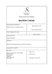
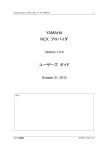
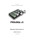
The definition for swept volume is the points that moving object contains over certain
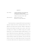
period of time. If the swept volumes for all the objects in a scene do not cross each other, then there is no collision between them during the certain period of time. But also
need to consider another situation, it might happen that the swept volumes crossed but
no collision occurred. This state demonstrated in the figure 1 and 2. In both conditions,
same swept volume in the x-y plane can be seen, but the collision occurred just in figure
1, not occurred in figure 2 [Jimenez 2000].
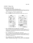
In order to avoid the incorrect estimation which happens in the figure 1 and 2, for each
two objects the sweep operation need to be done by the correlative movement of one
object with regard to the other object. In this condition, one of the objects is viewed as
fixed; the swept volume of the other object within this movement is calculated. The
drawback of this method still is the big amount of calculation work.
Figure 1 Extruded and swept volumes. In the extruded volumes situation, collision is detected [Jimenez 2000]
2. STATE OF ART
5
Figure 2 Extruded and swept volumes. The extruded volumes do not interfere, but the swept volumes in x-y
plane are the same as in figure 1 [Jimenez 2000]
2.1.3.
Multiple interference detection
Sample the object route and frequently make a static interference test to it is one of the
easiest way to deal with collision problems. The way of how sampling is done matters
the final result of this method. If the sampling is too rough, it will cause some collision
result missing. Also a too fine sampling will make the computation too huge. The recommended solution is to use adjustable sampling.
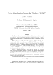
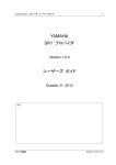
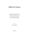
More experienced solution not only computes distance, but also get information about
direction. One solution in this way described in [Gilbert 1989] need to compute the
closest points of two convex polyhedrons at the instant time sample, and also determine
the line connect them. At the moment when the projections of the objects meet on the
line is used as the next time sample (In the figure 3). Therefore, this method can be considered as a mix of sampling and projecting onto subspaces which is in lower dimension.
Figure 3 Adjustable sampling. The start position is shown in (a), the closest points and the line connecting
them are computed. The projections of the objects on this line meet at instant (b), at this moment; the new
closest points are calculated at (c). At (d) the polygons collision occurred, the collision points is computed in
the same way [Gilbert 1989]
2. STATE OF ART
2.1.4.
6
Trajectory parameterization
In this method, the collision occurred time and related parameters can be found and analysed if the object trajectories are presented as functions of time. For instance, in the
simple situation a point movement is a linear motion, there is a triangle in the space
which is not moving, when the point moves if there is collision between them need to
consider. The parametric vector equation for the motion of the point and the triangle can
be expressed as:
p + (p’ – p) t = p0 + (p1 –p0 ) u+ (p2 –p0 ) v
(1.)
Where p is the initial position and p’ is the final position of the point. Parameter pi describe the triangle, u, v, t are the variables. u and v are parametric variables for the triangle plane, and t is a time variable which is 0 at the beginning of this process, and 1 at
the end. In the condition, if:
0≤t ≤1 AND u≥0 AND v≥0 AND u + v≤1
(2.)
Then the point intersects the triangle in the given time period, this conclusion got from a
research done by [Moore 1988]. In this parametric vector equation, it can be viewed as
three scalar equations in three unknowns; this can be simplified into one polynomial
which t is the variable.
2.1.5.
Gilbert-Johnson-Keerthi algorithm
The Gilbert–Johnson–Keerthi (GJK) distance algorithm is a way of determining the
distance between two objects. Different from other collision detection algorithms, the
geometry data does not need to be kept in any special format in this GJK algorithm, but
instead only depend on a support function to iteratively generate closer simplexes to the
right answer by using the Minkowski addition method for convex pairs [Gilbert 1988].
The GJK method solves nearness queries, for the given two convex polyhedra, it can
compute shortest distance between them; it also can find the closest pair of points. This
can be applied for any convex objects, if they can be defined by a support mapping
function [Ericson 2004].
2.1.6.
Tools for collision detection
Collision detection has been a basic problem in computer animation, 3D modelling, and
geometric modelling, and robotics. Usually the collision between two moving objects is
modelled by dynamic restraints and the analysis of the intersection in these applications.
Also the movements of the objects are restrained by several interactions, contains the
collision.
Several collision detection tools have been developed by researchers around the world,
most of them created in a virtual environment. The virtual environment is a world generated by computer, contain virtual objects in it. This type of environment should give
2. STATE OF ART
7
people the existence feeling, which means make the objects in the environment looks
solid. For example, the objects should not go through each other; the movement of objects should be as planned. When the object moves in the virtual environment, it takes a
lot of time for the collision detection algorithm to check the possible crash happens. So
it’s important to have a fast and effective algorithm.
After survey from the web, various collision detection tools are found, they are not only
to be used in robotics, and they are used in more wide area. A list of the tools:
Table 1 A list of different collision detection software
Name
SOLID
Description
Link
Software library for interference http://www.win.tue.nl/~gino/solid/i
detection
ndex1.html, [Bergen 1997]
RAPID
A robust and accurate polygon
interference detection library
A package for incrementally
computing the distance between
convex polyhedron
An improved implementation of
the Lin-Canny closest feature
tracking algorithm, as used in ICOLLIDE
A collision detection library for
large environments
A library for collision detection,
distance computation, and contact determination of threedimensional polygonal objects
undergoing rigid motion (rotation and translation)
Enhanced
GJK
V-Clip
V-COLLIDE
SWIFT
http://gamma.cs.unc.edu/OBB/,
[RAPID 1997]
http://www.cs.ox.ac.uk/stephen.ca
meron/distances/, [Cameron 1998]
http://www.merl.com/projects/vcli
p/, [MERL 1997]
http://gamma.cs.unc.edu/VCOLLIDE/, [Cohen 1998]
http://gamma.cs.unc.edu/SWIFT/,
[Ehmann 2000]
2.2.
Collision detection in current industrial robots
2.2.1.
Collision detection function in ABB robots
ABB robots are one type of the most widely used robots in the industry, production system and other service, the collision detection already designed as part of its functions.
This advance operation only can be found in some of the robots, for example it’s available in the ABB robot, KUKA robot, and Fanuc robot [Luca 2006]. In the ABB robot
controller RobotWare and the simulation and ABB robot offline programming software
RobotStudio, they both have the collision detection option but their methods are differ-
2. STATE OF ART
8
ent. In the RobotWare, the high sensitivity, model based supervision is used to detect
collision. The sensitivity option can be turned on and off, depends on how much force
applied to the robot. In the system parameters setting, in the motion supervision, it include path collision detection, jog collision detection, supervision levels for path and jog,
and collision detection memory to define how much robot moves after collision. When
robot detected collision, it will stop and move to the opposite way of the force which is
left. The robot will continue to work only after a collision message has been received.
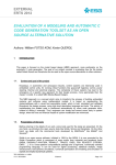
The picture below shows the order of events during and after the collision, first when
the collision is detected, then the motor torques are changed into opposite direction and
the robot will stop because of the mechanical brakes. After the robot stopped, the robot
will move in the opposite direction a small length, for removing remaining forces.
When the remaining forces are removed, the robot stops again and stays in the state
which is motors on [ABB Robotics 2007].
Figure 4 Speed and torque diagram [ABB Robotics 2007]
In the ABB offline simulation and programming software RobotStudio, it detect the
collision between objects in the station, it classify all the objects into two groups, objects A and objects B, if one object in objects A collides with one object in object B set,
the collision will be displayed in graphical view and logged in the output window.
2.2.2.
Collision detection in Microsoft Robotics Developer Studio
Microsoft Robotics Developer Studio (MRDS) is an environment for robotics control
and simulation built according to windows system. It can be used in academic research,
people who interested in robotics, and for commercial use in the robot industries. It has
the capacity of dealing with a wide range of robot hardware. MRDS is based on Concur-
2. STATE OF ART
9
rency and Coordination Runtime (CCR): a concurrent code library deal with asynchronous parallel operations based on .NET. This technique includes utilizing messagepassing and a small amount of services-oriented runtime. It is a type of Decentralized
Software Services (DSS); it allows the orchestration of numerous services to make
complicate behaviours. The features are: a visual programming tool, Microsoft Visual
Programming Language for making and fixing robot applications, interfaces which
based on web and windows, 3D simulation (including hardware acceleration), easy access to a sensors and actuators of the robot. The main programming language is Microsoft Visual C Sharp [Microsoft 2012].
One of the approaches to detect collision in the Microsoft Robotics Developer Studio
for a mobile robot is to install a laser device which can measure the distance. From the
hardware which Microsoft provided, the robot has two contact sensors in front and
back, and a 180 degree SICK Laser Range Finder (LRF) device [SICK 2008]. The collision detection performed like: the robot first scan the whole environment find the biggest open space, and then choose one direction within this range to move. In the situation if robot hit obstacle accidentally, the robot will stop and move back [Microsoft
2012].
Figure 5 Robot scan with laser range finder (LRF) [Microsoft 2012]
2.2.3.
Collision detection in CIROS Studio
CIROS Studio is a professional tool for building and simulating complicated workcell
models. It’s a software package that can easily be used for factory workflow and improves the communication between all involved sections and operators. CIROS Studio
is modular software which can be adjusted for the customer’s special requirement. The
basic modules contain: mechanics, electronics and geometry modelling module, a 3D
tool for making models in real time, controller simulation module, and the standard robot programming language, a tool for managing programs and position lists for robot, a
library of basic models, a support system includes tutorials, and a few other features
make CIROS Studio easier to use [CIROS 2012].
2. STATE OF ART
10
In CIROS Studio, the collision problems can be checked during the simulation process.
The collision detection function is included in the simulation module, once the simulation menu in the user interface is selected, user can active the sensor and collision detection function. When the collision detection user interface opened, in the index card
which name is selection, all the objects name will be shown there, user can choose
many of them to see if they have collision by selecting the selected object against each
other option [CIROS 2012].
2.2.4.
Model based real time monitoring method
For detecting final external collision, this method uses a model based real-time virtual
simulator of industrial robot. The applied method involves model based error detection
and separation, used to find information about lock of movement from an activated robot joint after contact with still obstacles, also online implementation of this method has
been tested from a research work of [Fawaz 2009]. In order to detect and identify existence of the motionless obstacles on the manipulator robot, a model based fault detection
and isolation (FDI) algorithm is made. By using the FDI algorithms created directly
from the related graph model, a list of analytical redundancy relation (ARR) together
with the corresponding fault signature matrix can be computed. The principal of this
approach is the usage of ARR theory, not to detect a faulty actuator, but to detect an
external joint obstacle which stops the normal operating of the faulty actuator [Fawaz
2009].
Figure 6 Residuals generation from virtual real-time simulator [Fawaz 2009]
2.2.5.
Derivation of kinematic parameters method
In this method, real-time collision detection algorithm, based on the application of oriented bounding boxes (OBB), and the triangle is used for finding the precise collision
2. STATE OF ART
11
point. The triangle means the models in this method are non-convex hierarchical polygons constructed by triangles. The point which collision occurred is used as a new end
of a kinematic chain; new kinematic parameters determined from collision triangles are
calculated. First generate a kinematics model from the virtual 3D model, by using these
acquired kinematic data; from the collision point as one end of the chain a new kinematic chain is generated. Then all points of the robot contains the points in the surface can
be controlled and the path of robot motion can be planned. The collision detection
method used here is part of multiple interference detection method. [Reichenbach 2003]
Figure 7 Kinematic chain is created from the point where collision occurred [Reichenbach 2003]
2.2.6.
Other robot modelling methods
There are also many other tools have been used in robotics modelling and collision research, one of them is SimMechanics toolbox. SimMechanics extends Simulink with the
tools for modelling and simulating mechanical systems. With SimMechanics, you can
model and simulate mechanical systems with a suite of tools to specify bodies and their
mass properties, their possible motions, kinematic constraints, and coordinate systems,
and to initiate and measure body motions [SimMechanics].
Similar as in MATLAB the robot system can be simulated in Dymola and Modelica, or
20-sim. Here the library provides three-dimensional mechanical components to model
rigid multi-body systems, such as robots. The robot system is built by connecting blocks
representing parts of the robot like link bodies, joints, actuators, etc. Figure 8 shows the
block scheme of a complete model of the KUKA robot including actuators, gears and
the controller [Kazi 2002].
2. STATE OF ART
12
Figure 8 Simulation of a robot with Modelica [Kazi 2002]
Another tool is planar manipulators toolbox with symbolic dynamics. Symbolic dynamics can be used to execute analysis and design studies on any mechanical system, which
can be modelled as a set of rigid bodies connected by joints, affected by forces, driven
by defined motions, and limited by constraints [Hollars 1994]. The dynamic model is
shown in figure 9.
Figure 9 Dynamic model made by planar manipulators toolbox [Hollars 1994]
After reviewing many of the modelling approaches and collision detection tools in this
chapter, it shows that each approach has their own advantages and disadvantages, and
some of them are complex. An approach can be suggested to simplify robot workcell
modelling for collision detection; this approach is presented in the Chapter 3.
13
3.
APPROACH
In this chapter, the approach of modelling robot and workcell, developing the collision
detection tool is presented. This chapter is arranged in the order: First is the approach
for modelling 3D objects, robot and workcell in MATLAB. After these sections, is the
creating of collision detection tool, this includes the development of collision detection
algorithm. In the end of this chapter, is the trajectory planning approach for collision
detection.
3.1.
Creating 3D objects and workcell in MATLAB
3D modelling in the computer graphics field is defined as a technique of building mathematical representation for 3D physical objects by particular software [Liu 2010]. In
this thesis, MATLAB is the main modelling software used. MATLAB program is very
good at numerical computing, visualization and analysis. MATLAB is used for modelling the robot with the aid of robotics toolbox for MATLAB. In this thesis the objects in
the robot workcell is also modelled, it contains the conveyors, cube and sphere shape
objects in the workcell. MATLAB is also used for collision detection, this include the
creation of graphical user interfaces for controlling robot and workcell, and development of the collision detection algorithm. Practical simulation system and analyse tools
are very important for modelling and solving collision problems. In such system, it requires the tools can make geometric modelling and physical sampling [Lin 1996]. In
this section, the approach of building 3D objects and workcell in MATLAB is introduced.
For building the 3D objects in MATLAB, there are several ways to do this. The purpose
of making 3D objects is for building the robotics working cell and components within
the working cell. The most basic elements for constructing the workcell is the line element, multiple lines can construct different size of cubes. The command Line creates a
line objects with default values x= [0 1] and y= [0 1] [MATHWORKS]. The syntax of
line is:
line (x, y, z, ‘property name’, property value)
(3.)
Beside the line command, another command voxel is used. Voxel made by [Joel 2003]
is a simple function to draw a cube or cuboid in a specific position of defined dimensions in MATLAB. The transparency of voxel also can be defined in this function. For
making complex shape, many voxel can be used to form it. This algorithm is presented
here.
3. APPROACH
14
Algorithm 1 Create 3D objects in MATLAB
Name
Description
Data structures:
i
d
c
x
alpha
nargin
Steps:
(1)
(2)
(3)
(4)
(5)
(6)
(7)
(8)
(9)
(10)
(11)
(12)
(13)
(14)
(15)
(16)
(17)
(18)
(19)
(20)
Create 3D objects in MATLAB
For drawing a 3D cube shape object in a MATLAB plot, the function voxel is used. The approach used in this function is by finding
a series of coordinates along x; y, z axes, and then use patch function to make the cube [Joel 2003].
The start point coordinates of the cube.
Size of the cube in three dimensions.
The colour of cube.
Both the start coordinates [I (1), I (2), I (3)] and the size of the cube
in three dimensions [d (1), d (2), d (3)].
The transparency of the cube.
The number of function arguments.
function voxel which contains variables I, d, c, alpha
switch among number of function arguments
case the number of function arguments is 0
display Too few arguments for voxel
return
case nargin = 1
the default length of side of voxel is 1, the default
colour of voxel is blue
case nargin = 2
then the colour of voxel is blue
case nargin = 3
then the value of alpha is 1
case nargin = 4
do nothing
otherwise
display Too many arguments for voxel
end
assign a three columns and eight rows matrix value for x, x is constructed by the start coordinates I (1), I (2), I (3), and the
size in three dimensions d (1), d (2), d (3), and zeros in the
corresponding place
for n from 1 to 3
if n = 3
then sort the rows of x first in ascending order for
3. APPROACH
15
the third column, and then sort the rows of x in
ascending order for the first column
(21)
(22)
else
sort the rows of x first in ascending order for the
number n column
and then sort the rows of x in ascending order for
the n+1 column
(23)
(24)
(25)
(26)
end
get the first 4 rows of values of the three columns of x
construct a cube shape polygon by the value above, by
function patch
get the 5 to 8 rows of values of the three columns of x
construct a cube shape polygon by the value above, by
function patch
(27)
(28)
(29)
end
Other 3D objects made in MATLAB is the sphere, the sphere is made by the command
sphere in MATLAB. The sphere function generates a sphere in the x, y, z coordinates.
The script written as:
Algorithm 2 Create sphere in MATLAB
Name
Description
Steps:
(1)
(2)
(3)
(4)
(5)
Create sphere in MATLAB
For draw a sphere in MATLAB, command surf and mesh are used
for construct the sphere.
figure (1)
set x, y, z as parameters of the function sphere
set radius value r
set the centre coordinates x, y, z
create a shaded surface of sphere by the centre coordinates and
the radius
In step (2), it wrote as [x, y, z] = sphere (n) this returns the coordinates of a sphere in
three matrices that size are n+1 by n+1, then in step 5, draw the sphere by commanding
surf or mesh.
The conveyor and workcell frame are created by repeating use the commands voxel and
line; user can define the place where is the start point of the workcell, then specifying
the size of the workcell. And by using several cube objects, the conveyor and even more
complex shapes can be made in MATLAB.
3. APPROACH
3.2.
16
Modelling the robot by robotics toolbox in MATLAB
MATLAB is widely used in the area of computer graphics, linear algebra and simulation. It is usable on a very broad range of computer platforms, and it is highly used in
universities for studying, teaching and research. The fundamental functions of
MATLAB can be extended by different toolboxes; many of the toolboxes can be obtained from companies or under various open-source licenses. The basic data types of
MATLAB are vector and matrix, which are very suitable for the problems in both robotics and computer vision [Corke 1996]. In this thesis work, the open source extension,
robotics toolbox for MATLAB is used for modelling robot and computing robotics parameters.
The robotics toolbox is a software package allows user to create and manipulate data
types which is fundamental to robotics, like homogeneous transformations, trajectories.
In this toolbox, functions are provided for arbitrary serial-link manipulators; include
forward and inverse kinematics, Jacobians, dynamics [Corke 1995].
This toolbox is suitable for simulation, it is also very helpful for analysing the results of
experiments from real robots, and it is a powerful tool for education and research. The
principle of the toolbox is according to a general approach by using description matrices
to denote the kinematics and dynamics of serial-link manipulators. The inverse dynamics is computed by using the recursive Newton–Euler formulation. In the beginning it is
designed to be used with MATLAB, but now it also can be used with Simulink [Corke
1995]. For creating robot in MATLAB, the algorithm for this usage is presented below.
Algorithm 3 Create robot in MATLAB
Name
Description
Data structures:
Create robot in MATLAB
For making graphical robot in MATLAB, robotics toolbox is used
α
Rotation angle.
θ
Rotation angle.
a
d
Translations in Denavit-Hartenberg link parameters.
Translations in Denavit-Hartenberg link parameters.
Steps:
(1)
(2)
(3)
(4)
(5)
create the link from α, a, θ, d for link 1 to n
set initial position value q
create the robot from link 1 to n
figure 1
plot the robot with robot and q
Here parameter α, a, θ, d are determined by Denavit-Hartenberg (DH) method, link is
the command for creating manipulator link, the command for constructing robot is robot
in robotics toolbox in MATLAB.
3. APPROACH
3.3.
17
Graphical user interface for collision detection
The graphical user interface (GUI) is a graphical display in one or several windows that
contain controls and make it possible for the user to do tasks interact with the MATLAB
program. The user only needs to click some buttons in the GUI; they do not need to
write the script or commands in the MATLAB command window to do the work. And
the users do not need to know the working principle behind the GUI interface. The most
usual objects displayed in GUI are: menus, toolbars, push buttons, radio buttons, sliders,
edit boxes, list boxes.
The working principle of GUI is: when the user operates a control, the GUI will give
response to each control. One main part of GUI algorithm is the call back functions. The
call back functions for call back to MATLAB, ask it to do certain action. The call back
action usually generate by user pushing a button in the GUI, or by user selecting an item
from the menu, or by the user input a type of value. The GUI has reaction to these
events. The task for the GUI maker is to define the callbacks and the components, the
events. There are two ways of writing call back code in MATLAB, one is that write
callbacks as MATLAB functions which save as m-files, the other way is write callbacks
as part of MATLAB strings [MATHWORKS].
When designing graphical user interface in MATLAB, there are several things to consider. Before starting to create it, the requirements and the goals of the GUI should be
considered; this consists of defining the input, output, display, and the behaviours of the
GUI. During the design of GUI, each of its components should be programmed for
functionally correctly. The process of designing GUI is presented in the picture below.
Figure 10 Process of designing GUI [MATHWORKS]
3. APPROACH
3.3.1.
18
Basic model of collision detection user interface
At the early stage of the user interface for collision detection development, a basic user
interface is made for the requirement of detection collision between a robot and workcell. The workcell here refers to a cuboid where the robot is located inside it. The GUI
contains two edit boxes and one push button, one of the edit boxes is for inputting the
robot position, after pushing the button, and the other edit box will display the result of
the robot collision situation. The algorithm for this is presented in algorithm 4.
Algorithm 4 Model of collision detection interface
Name
Description
Steps:
(1)
(2)
(3)
(4)
(5)
(6)
(7)
(8)
(9)
(10)
(11)
(12)
(13)
(14)
(15)
(16)
(17)
(18)
Model of collision detection interface
This algorithm is for making a basic model of collision detection
graphical user interface, it defines the properties and behaviours
of all components of the GUI window, when user executes the
file, it creates a figure window with one input box, one output
box and one push button.
function name is GUI_M
make a figure for the frame of this GUI, define position, size
and name
create user interface control object for first edit box, this includes define position and number of lines in this edit
box, value type, font weight, horizontal align, font size
create user interface control object for the second edit box, this
includes define position and number of lines in this edit
box, value type, font weight, horizontal align, font size
create user interface control for push button, this include define
the units, position, horizontal align, type of word to display, font size, callback (it calls the function pb_call)
give the first edit box controllability
function pb_call (varargin)
get the string from edit box and give it to variable w
set initial position value q1 = w
create link object l1 to n
create robot by l1 to n
calculate the forward robot kinematics
get robot end effector coordinate Tx, Ty, Tz
if the robot’s end effector coordinate is not within the workcell
display collision
else if robot’s end effector coordinate is within the workcell
display no collision
end
3. APPROACH
(19)
19
set this result to edit box 2
This algorithm contains two parts, step (1) ~ (6) is for making the outward appearance
of the GUI, step (7) ~ (19) is the call back part of the push button, the push button is
made within the step (1) ~ (6).
3.3.2.
Collision detection interface
At the beginning of making the GUI for collision detection, the requirements considered
are: the detection of collision and it need to be able detect collision in real time. Based
on these two requirements, the original drivebot file is modified. There is collision display part has been added to the original interface. Drivebot is a function for driving a
graphical robot, it’s a pop up window contains sliders for moving each joint. When user
moves the sliders by mouse, it will move the corresponding robot link in the screen.
This interface is very good for the view of robot joints, links and workspace. [Corke
2008] By using this modified drivebot function, it makes whenever user moved the slider in interface for controlling the robot links, then the user can see if the robot collision
with other object, the result is shown in the same interface. The main algorithm for this
approach is presented below.
Algorithm 5 Real time collision detection
Name
Description
Steps:
(1)
(2)
(3)
(4)
(5)
(6)
(7)
(8)
(9)
(10)
(11)
(12)
(13)
(14)
(15)
(16)
Real time collision detection
This algorithm is made for detecting collision in real time, when user
moves the slider in the interface, at the same time in the right upper
part of the interface, it will show if there is collision occurred.
function name is drivebot
give value for the back ground colour
if input a is character array
set a = name of robot
set b = joint index
set q as initial position of robot
for robot and initial position q
if the input array q is empty
then q = zeros
end
then get value from slider
or get value from text box
plot robot with the initial position q
end
get forward kinematics for each joint space t6
compute the coordinates of the cube which located near the
3. APPROACH
20
robot
compute the minimum and maximum values for the cube
coordinates in x axis, Xmin and Xmax, in y axis,
Ymin and Ymax, in z axis, Zmin and Zmax
if the end effector’s coordinates t6 within the cubes’ coordinates Xmin, Xmax, Ymin, Ymax, Zmin, Zmax
display collision
else
display no collision
end
(17)
(18)
(19)
(20)
(21)
(22)
(23)
(24)
else
create the GUI for this drivebot function by defining the
width and height
if the number of function arguments less than two
set q = zeros
else
if the input b is character array
set q = b
end
end
compute the forward kinematics for each joint
check if there are any graphical robots of this name, if so
then use them, otherwise create a robot plot
get the current joint configuration of graphical robot
make the sliders for each robot link
create three text boxes for x, y, z axis value of the robot end
effector
(25)
(26)
(27)
(28)
(29)
(30)
(31)
(32)
(33)
(34)
(35)
(36)
(37)
end
In this algorithm, it can be seen as it is divided into two parts by the else in the step (25),
before else it mainly making the connecting with the part after else like getting data, and
the calculation of collision between robot and the cube objects in the workcell. The part
after else mostly for making components for this graphical user interface, like build the
siders, input boxes, display result box etc. Within this chapter of code, the commands
from robotics toolbox are: fkine for computing the forward kinematics and the end effector’s coordinates can be getting from it, robot for building robot object. The improvement of this interface is: it can detect the collision in real time, when user moves
the slider; this algorithm computes the collision at the same time.
After this real time collision detection interface is made, there are more requirements
found should be considered. One function should be considered in this interface is that it
should be able to load graphical robot and its workcell. When user click buttons in this
3. APPROACH
21
interface, it will automatically insert one kind of shape into the MATLAB robot model
picture; this interface will provide different shape choices, like outside frame, cubes,
conveyors, etc. At the same time, after certain button is pushed, it is able to see if the
collision happened from another drivebot interface.
Next requirement to be considered is: this interface should allow user input the cube or
sphere shape of objects in the position where the user want it be. And also the user can
define the size of the objects. Based on this concern, the approach for making a collision
detection tool is made. There are six edit boxes below the add cube button, this allows
people input the coordinate and size of the cube, it can just insert to the robot cell. And
there is generate sphere button in the choice; also four input boxes allow people input
the coordinate and radius of the sphere. When the developments above are done, next
task is to integrate the real time collision detection function to this interface. The algorithm for this approach is:
Algorithm 6 Collision detection interface
Name
Description
Steps:
(1)
(2)
(3)
(4)
(5)
(6)
(7)
(8)
(9)
(10)
(11)
(12)
(13)
(14)
(15)
Collision detection interface
This algorithm is for making a collision detection interface which
also can load graphical robot, workcell and other objects. This interface can detect the collision between robot and environment.
initialization of the code
function name as frame_pushbutton_callback
figure 1
create a frame by voxel function by defining coordinates and size
create the top part of the frame by voxel function defining coordnates and size
create the bottom layer of the upper part of frame by voxel function
defining coordinates and size
create the middle layer of the frame by voxel function
create another middle layer of the frame by voxel function
create the base for the frame by voxel function
create the outer layer lines
store the variable data in this section as GUI data
make a function which name is cube_pushbutton_callback, for the
cube which is going to be inserted in the working cell
get the string value of the x, y, z axis coordinate of the start point of
the cube from the edit box
get the string value of the size of cube in x, y, z axis from edit box
use the six values got from above six steps, build a cube by voxel
function, the cube will be inserted in the same figure with the
3. APPROACH
22
(16)
graphical robot
store the variable data in this section as GUI data
(17)
(18)
(19)
(20)
function which name is productionline_pushbutton_callback
create a conveyor line by voxel function
create the holding part of the conveyor by voxel function
store the variable data in this section as GUI data
(21)
function name is addRobot_pushbutton_callback, this is for loading
graphical robot
create link object l1 to n
get the value of initial joint variable q
construct a robot object from a cell array of link objects
hold the current graph
store the variable data in this section as GUI data
function which name is RemoveFrame_pushbutton_Callback
remove all the figures
store the variable data in this section as GUI data
(22)
(23)
(24)
(25)
(26)
(27)
(28)
(29)
(30)
(31)
(32)
(33)
make a function which is for creating the text box, for inputting x
axis value, for constructing cube
get the input value, and convert it to the double data form
store the variable data in this section as GUI data
repeat this same action for y axis input text box and z axis input text
box, and also for the text box, for inputting the size of cube in
x, y, z axis
(34)
(35)
(36)
(37)
(38)
(39)
make a function for creating sphere object in the workcell
create a sphere, and get the coordinates of the sphere x, y, z
get the size value of the sphere from the input box
get x, y, z coordinates of the centre of the sphere from input boxes
create a shaded surface for the sphere by command surf
store the variable data in this section as GUI data
(40)
make a function which is for creating the text box for inputting x
axis value of sphere centre
get the input value, and convert it to the double form
store the variable data in this section as GUI data
repeat this same action for y axis input text box and z axis input text
box, and also for the text box, for inputting the radius of
sphere
(41)
(42)
(43)
3. APPROACH
(44)
(45)
create a function for making the collision detection button
if the coordinates of the robot end effector in x, y, z axis within the
cube or the sphere inserted to the robot workcell
display collision
else
display no collision
set the result to the handle object of result
store the variable data in this section as GUI data
(46)
(47)
(48)
(49)
(50)
3.4.
23
Collision detection algorithm
Collision detection is an important issue in robotics and computer graphical theory area;
appear in motion planning, graphical programming, control, dynamic simulation, virtual
reality. Whether a rigid body moving along a given route in touch with any of objects at
any point of the route, that is the collision detection problem. In a wider definition of the
problem, should determine all the contacts. In all situations, it is very important that the
calculation result of collision detection is accurate. The result of collision detection of
the objects influences the action of robot and affects the output of the simulation of robots, like some of the result of collision will be used when design and evaluate product.
Most common approach for collision detection is based on detection of interface and
distance calculation.
In this section, the main collision detection approach is presented. There have been
three approaches developed for collision detection between robot and cube, sphere
shape objects. The first collision detection algorithm is made for detecting collision between graphical robot and cube shape objects around it. The second collision detection
algorithm is also for detecting collision between robot and cube shape object, but using
another way to do it, the distance between robot and objects has been calculated. The
third collision detection algorithm is made for detecting collision between robot and
sphere shape objects.
For the first situation, only concern the collision between robot and the cuboid workcell
and cube shape objects, the algorithm is presented below:
Algorithm 7 Collision detection by comparing coordinates for cube shape objects
Name
Description
Collision detection by comparing coordinates for cube shape objects
This algorithm is for detecting the collision between robot and
cube shape objects around it, the approach used for detecting collision is by comparing the coordinates of the robot and the objects,
if the coordinates of the robot is within the coordinates of the ob-
3. APPROACH
24
jects, then collision occurred.
Steps:
(1)
(2)
(3)
(4)
(5)
(6)
(7)
(8)
(9)
(10)
create a link object l1 to n
get the value of initial joint variable q
construct a robot object from a cell array of link objects and the
initial joint q
compute the forward kinematics for each joint space point defined by q and robot object, and set this result to T
get the end effector coordinate in x, y, z axis from T
if the end effector’s coordinates within the cube’s coordinates in
X, Y, Z
display collision message
else
display no collision message
end if
For the second situation, it needs to determine if the robot has collision with the cube
objects around it. The coordinates of the cubes are defined, so all the coordinates within
the cubes is searched by a for loop in MATLAB, if the distance between any of those
coordinates and the coordinates of the robot less than 1mm, then they have collision.
The algorithm for this part is:
Algorithm 8 Collision detection by calculating distance for cube shape objects
Name
Description
Steps:
(1)
(2)
(3)
(4)
(5)
(6)
Collision detection by calculating distance for cube shape objects
This algorithm shows another approach to solve collision detection problem between robot and cube shape objects, which is to
calculate the distance between robot and objects, if they are equal
to zero then collision occurred.
for each coordinates between the start and the end coordinates for
x axis of cube1
for each coordinates between the start and the end coordinates for y axis of cube 1
for each coordinates between the start and the end coordinates for z axis of cube 1
repeat the 3 steps above for all the cubes
if the distance between the robot’s end point and one point within
the cube is equal to zero
display collision message
3. APPROACH
(7)
(8)
(9)
(10)
25
end for
end for
end for
end if
In the third situation, is to detect the collision between graphical robot and the sphere
shape object in the workcell. The algorithm of this part is:
Algorithm 9 Collision detection by comparing distance for sphere shape objects
Name
Description
Steps:
(1)
(2)
(3)
(4)
(5)
(6)
(7)
(8)
(9)
(10)
(11)
(12)
Collision detection by comparing distance for sphere shape objects
This algorithm is for detecting the collision between robot and
sphere shape objects in the workcell, the approach used for detecting collision is by comparing distance between the centre of the
sphere and the coordinates of the robot. If the absolute value of
the distance difference is greater than the radius of the sphere,
then no collision occurred, otherwise then the collision happened.
create a link object l1 to n
get the value of initial joint variable q
construct a robot object from a cell array of link objects and the
initial joint q
compute the forward kinematics for each joint space point defined by q and robot object, and set this result to T
get the end effector coordinate in x, y, z axis from T, name them
as T1, T2, T3
assign a value for the radius of the sphere
get the coordinates of the sphere centre point, name them as xs,
ys, zs
if absolute value of the distance difference of the centre point of
sphere and the robot manipulator is greater than the radius of the
sphere
display no collision message
else
display collision message
end if
After introduced these three approach of collision detection, with the collision detection
user interface described earlier in this chapter, the usage of this entire collision detection
tool is: The objects appear in the workcell include conveyors, cubes, spheres.
3. APPROACH
3.5.
26
Trajectory planning for collision detection
There are two ways to generate trajectory, one is joint space schemes, and another is
Cartesian space scheme. Joint space method is the path shapes (in space and in time) are
described in terms of functions of joint angles. In Cartesian space schemes, it consider
methods of path generation, in which the path shapes are described in terms of functions
which compute Cartesian position and orientation as function of time [Craig 2004].
When trajectory is planned in the joint space, its mathematical representation is cubic
polynomials. A cubic polynomial has 4 coefficients, may be used to satisfy both position and velocity constraints at the initial and final positions. For joint variable q i , the
constraints are:
q i (t 0 ) = q 0
(4.)
q i (t f ) = q1
(5.)
′
Where t 0 is the starting time, t f is the ending time, q 0 and q 0 are the specified initial
position and velocity, q1 and q′1 are the specified initial position and velocity. The cubic
polynomial for joint position and its derivative for joint velocity are shown below.
(6.)
q i (t) = a0 + a1 t + a2 t 2 +a3 t 3
2
q̇ı (t) = a1 + 2a2 t + 3a3 t
(7.)
Where the position value q is the degree of the joint, in this thesis the collision point
will be focused, so using the joint space method is not very suitable for catch the collision points. Here Cartesian space method will be used to find the collision point, because it can track the coordinates of points in the trajectory. Once these points are
known to the robot, it can avoid collision [Craig 2004].
For current used collision free trajectory planning approaches, most of them have models of manipulator, the work area, and all the obstacles in the area. When the user defines the desired goal point of the manipulator motion, and let the system determine
which route to go so that the goal is reached without the manipulator hitting any obstacles.
The approach used in this thesis, is to build both models of the robot and the obstacles,
the obstacles can be different shapes, but here a cube shape model is made for them all,
even if the obstacle is a sphere, we assume it is in a cube shape bounding box. By using
the robotics toolbox in MATLAB, the Cartesian trajectory can be plotted by command
ctraj. When the figure of trajectory of the robot tooltip is obtained, then plot the range of
x, y, z coordinates of the bounding box in the same picture. After getting both trajectory
of the robot and bounding box in the same plot, the figure can be analysed, at the place
where the first time robot’s x, y, z coordinates are all within the bounding box’s coordinates, that is the first point the collision start, by graphical analyse tool, the points causing collision can be found. The algorithm for this method is presented below:
3. APPROACH
27
Algorithm 10 Trajectory planning for collision detection
Name
Description
Steps:
(1)
(2)
(3)
(4)
(5)
(6)
(7)
(8)
(9)
(10)
(11)
(12)
(13)
Trajectory planning for collision detection
This algorithm first build trajectory of the robot, then plot the coordinate range of the bounding box of obstacle in the same figure,
after these steps, graphical analyse tool is used for analyse the
collision points.
create link objects l1 to n
define the initial position for robot
plot robot
build a bounding box model for obstacle by voxel function
define the start point for robot trajectory
define the end point for robot trajectory
define the time length for this motion
create the path vector r with continuous derivatives by jtraj
function
create the Cartesian path with smooth acceleration r
plot this trajectory
hold on the current figure
get the start and end point value of the obstacle bounding box in x,
y, z axes, totally 6 values
plot the six values got from step (12) as 6 lines in the figure
In this chapter, the approach of modelling the robot workcell for collision detection is
presented. In the beginning the approach for modelling robot is described, this is done
with the robotics toolbox for MATLAB. Then to build the workcell, basic functions in
MATLAB for constructing line, cube elements are used; a special function voxel is used
for making cube shape objects more convenient. For more complex objects like a conveyor, it can be made by a combination of several cubes and lines, with the basic elements like line and voxel; they can make most objects in the robot work environment.
When the models of robot and workcell are built, next is to make the function for collision detection. In this approach, first step is to build graphical user interface to gather all
the modelling functions into the same panel, then to make the real time collision detection function, after combining modelling and collision detection functions into the same
interface, the collision detection tool can be realized. For the next chapter, the implementation of all the mentioned steps of this paragraph is detailed in the same order in
the following chapter to derive overall implementation.
28
4.
IMPLEMENTATION
In this chapter, the implementation of the approach described in Chapter 3 for modelling
robot workcells, and making the collision detection tool is detailed. The robot model
selected to demonstrate the usage of the approach is Sony SRX-611. Final results of
robot and workcell modelling, collision detection user interfaces implementation are
presented in this chapter.
4.1.
The robot and workcell
In Chapter 3, the approach of modelling robot and workcell is discussed. In this chapter,
the Sony SRX-611 robot and the corresponding workcell is chosen as an example, to
demonstrate the usage of the modelling approach. The real SRX-611 robot and workcell
are located in the Factory Automation System and Technologies laboratory in Tampere
University of Technology.
4.1.1.
Sony SRX-611 High-Speed Assembly Robot
The Sony SRX-611 robot is built with brushless AC servo motors and absolute encoders; PLC is one way of control of the robot. The robot weights 35 kg and the suggested
payload is from 2 kg to 5 kg, it can operate with maximum 5 kg components; it mainly
do parts assembly and material handling tasks. The technical advantage of Sony SRX611 are: time and cost savings, reusable, which means when apply some change to the
installation, the equipment can be used as a standard unit, high quantity of production
for parts handling task, high accuracy in the production to ensure the quality, low floor
space requirement, this made easy to reach the device and space saving. The appearance
of the robot is shown in figure 11. Because the features of the robot are high velocity,
precision and easy operation, this type of robot has a wide range of usage in many
fields. For instance they can be used in electronic production, manufacturing, consumer
goods and more, information about Sony SRX-611 robot got from homepage of
[PRODEMO] company. In the figure 12, is a list of the specifications of this robot.
4. IMPLEMENTATION
29
Figure 11 Sony SRX-611 robot [PRODEMO]
Figure 12 Specification of Sony SRX-611 robot [SONY-SRX]
4.1.2.
Sony SMART Cell
The Sony SMART Cell is made under the standard of electronic production industry. It
contains operator interface, conveyors, safety control systems, frames, and can be adjusted to perform most handling or assembly task. The entire cell weights 450 kg, suitable for working at 5 to 40 degree of room temperature, with the maximum 90% humidity. The right power supply for it is AC 220V, 16A. This robot working cell is also
called Sony smart cell; the Sony SRX-611 high speed assembly robot is installed in it.
Some features of this cell are: it capable of processing 5 kg parts, six tool change heads
for loading different tools and very flexibility, Sony conveyor system made it easy for
connecting with feeders, pallets for handling materials and components, mounted with
Omron PLC, high accuracy frame and the mounting board. The picture of the workcell
is shown in figure 13.
4. IMPLEMENTATION
30
Figure 13 Sony SRX-611 robot workcell [SONY-SRX]
4.2.
Define and model the robot
For modelling the Sony SRX-611 robot, MATLAB and robotics toolbox are used. In
this toolbox, the link and robot commands are the main commands for constructing
graphical robot in MATLAB. The main part of MATLAB code to construct robot is
discussed below.
Code 1 Define and model the robot
l1 = link ([0 350 0 -50 0], ‘standard’)
l2 = link ([0 250 0 0 0], ‘standard’)
l3 = link ([0 0 0 -720 1], ‘standard’)
l4 = link ([0 0 0 -300 0], ‘standard’)
qInput=[1.885 0.062832 -0.1885 0.75398]
rob = robot({l1 l2 l3 l4})
figure
plot(rob, qInput) % For plotting the robot
drivebot(rob)
First four lines in the code are used to create a separate link of the manipulator. For instance the first link is created with the four parameters according to the standard Denavit-Hartenberg notations. The first parameter is alpha which is the angle between Z1
and Z2 measured about X1 , a is the distance from Z1 to Z2 measured along X1, theta is
the angle between X0 and X1 measured about Z1 , d is the distance from X0 to X1
measured along Z1 . The parameter selected here is based on the size of real Sony SRX611 robot. The fifth line in the code is a set of values for the initial position for each
links. The sixth line of the code is using robot command to build graphical robot. The
4. IMPLEMENTATION
31
seventh and eighth lines in the code are for making a picture and plotting the robot in a
separate window. The last line of this code is for manipulating the links of this robot.
The robot is built in MATLAB after executing the code above, a picture of this graphical robot is shown in the figure 14.
Figure 14 A Sony SRX-611 robot model in MATLAB
4.3.
Rough model of the robot workcell
At the beginning of modelling the entire robot workcell, it started from building a simple cube which robot is located in it. There are different ways to build a 3D cube in
MATLAB environment; in this thesis a MATLAB function named voxel is used. Voxel
is a simple function to draw a voxel (cube, cuboids) in a specific position of specific
dimensions in a 3-D plot. Transparency of the voxel can also be defined. Many voxels
can be arranged to construct new shapes. The voxel command and the dimension and
the location of the cube is defined here, the command for building the workcell is:
Code 2 Voxel function for making the robot workcell
Voxel ([-700 -700 -1750],[1400 1400 2450],[0.2 0.0 0.8],0.2)
In this line of code, the first set of three values are the starting point of the cube shape
frame, these three values represent the start point value in x, y, z axes in millimetre. The
second set of value means the size of this cube shape frame in x, y, z axes. The third set
of value means the colour of this cube, the last value of this code is the value of transparency, the value range is from 0 to 1, 0 means transparent while 1 represents opaque.
The picture of robot and its working cell rough model is:
4. IMPLEMENTATION
32
Figure 15 A rough model of robot and workcell
4.4.
Collision detection for rough model of robot workcell
After the workcell model is built, the next step is to detect collision between this cell
and the robot. The approach used for detecting collision between robot and the working
cell is: by comparing the coordinates of the robot end effector and the coordinates of the
workcell cube, if the x axis coordinate of robot end effector is greater than the maximum x axis coordinate of the cube, or less than the minimum x axis coordinate of the
cube, and apply this rule also to the y axis and z axis, then the robot and cell have collision. Otherwise the robot and workcell cube do not have collision. The implementation
of this approach wrote in MATLAB m-file is:
Code 3 Collision detection for rough model of workcell
x1=-700;x2=700;
y1=-700;y2=700;
z1=-1260;z2=1260;
T = fkine (rob, qInput)
T1=T (1, 4)
T2=T (2, 4)
T3=T (3, 4)
If T1<x1|| T1>x2 || T2<y1|| T2>y2 || T3<z1|| T3>z2
display(‘Collision’)
Else
display(‘No Collision’)
End
The first three lines of code are the minimum and maximum value in x, y, z axes for the
cube shape object. In the fourth line of code, the command fkine is used for determine
robot forward kinematics for serial link manipulator. From the calculation of robot forward kinematics, the coordinates of the robot end effector for x, y, z axis coordinate can
be obtained, and they are T1, T2, and T3 respectively, which are written in fifth to seventh lines. In the eighth line of the code, is the condition for detecting collision, if any of
the coordinates of the robot is out of the cell’s coordinate range, and then the collision
occurred. In the ninth line to the last line of the code, is for displaying the collision result. When this m-file get joint variables as input, as the result of m-file execution, user
4. IMPLEMENTATION
33
can get information about whether the collision of robot manipulator and the cube has
occurred. This is a very basic and simple way to detect collision, which is used at the
beginning of collision detection development in the thesis.
4.5.
3D objects in the workcell
As trails for drawing the entire robot workcell work, at this stage more cube shape objects has been tried to add to the cell. Here the voxel function is used again to create
new cubes and shapes constructed by cubes. The voxel function is easy to use, need to
define the start point coordinates and the size of the cube, and then define the colour of
it. By repeating this way of making cubes, the result of this process is shown in the figure 16.
Figure 16 Robot workcell with many cube shape objects
The sphere shape object is also made in MATLAB for adding sphere into the workcell.
The approach of creating sphere is presented in the chapter 3 algorithm 2.
4.6.
General function for collision detection
For detecting collision between robot and the cube and sphere shape objects inside the
robot workcell, several approaches have been found. All of them are three approaches,
two approaches are used for detecting collision between robot and cube shape objects,
one approach is used for detecting collision between robot and sphere shape objects.
The first approach for the cube shape object and robot is: by calculating the distance
between robot end point and a point which within a cube in the air, if the distance is less
than 1mm, then it will give output collision. To get the inside coordinates of a cube,
here is to get the entire sets of coordinates along x axis, y axis, z axis, they have 1mm
interval between each other in each axis (for example, in x axis, the x axis coordinates
are: 100, 101, 102,103, 104….400). The distance is computed by equation:
Distance = �x 2 + y 2 + z 2
(8.)
4. IMPLEMENTATION
34
The code for this part is:
Code 4 General function for collision detection
m= [-700 200 -200];
n=[100 400 400];
x1=m(:,1);
y1=m(:,2);
z1=m(:,3);
x2=x1+n(:,1);
y2=y1+n(:,2);
z2=z1+n(:,3);
xaxis=x1:x2;
yaxis=y1:y2;
zaxis=z1:z2;
For xaxis=x1:x2
For yaxis=y1:y2
For zaxis=z1:z2
If sqrt((T1-xaxis)*(T1-xaxis) + (T2-yaxis)*(T2-yaxis)+(T3-zaxis)*(T3zaxis)) < 1
Display (‘Collision’)
End For
End For
End For
End If
In the first line of this code, is the start point of the cube shape object. The second line
of code is the size of this object in x, y, z axes. The following six lines of code is for
getting the starting point and ending point value for the cube in x, y, z axes. The ninth to
eleventh lines of code are for putting the coordinates of the cube into three variables,
they are xaxis, yaxis and zaxis. From the twelfth to fifteenth lines are using for loop to
search all the coordinates values of the cube in three dimensions. The sixteenth line of
code is a calculation of the distance between robot and the cube in x, y, z axes, to see if
the distance is less than 1mm. This threshold value also can be modified by user. In the
seventeenth line of the code is a displaying of collision result.
The second approach used for detecting collision between robot and cube shape objects
is by comparing the coordinates of the robot end effectors and the maximum and minimum value of coordinate of the cube in each axis.
The approach used for detecting collision between robot and sphere shape objects is: by
comparing distance between the centre of the sphere and the coordinates of the robot. If
the absolute value of the distance difference is greater than the radius of the sphere, then
no collision occurred, otherwise the collision happened. The main part of the collision
detection code is presented below.
Code 5 Collision detection code for robot and sphere shape objects
r=50 % set a value for the radius of the sphere
xs= -700 % coordinates for the sphere centre
ys= 200
zs= -200
If abs(T1-xs)>r && abs(T2-ys)>r && abs(T3-zs)>r
display('No Collision')
else
display('Collision')
4. IMPLEMENTATION
35
End
The first line of this code is used to set a value for the radius of the sphere. The second
to the fourth line of this code are used for giving the sphere centre values to variables.
The fifth line of the code is the condition for determining collision between sphere and
robot, if the absolute value of the distance between robot and sphere is greater than the
radius of the sphere, then they do not have collision. The last four lines of the code are
used for displaying results.
4.7.
Detect the collision in real time
After being able to get the result of collision from the input position manually, at this
part it is improved to be able to see the result in real time, whenever user moves the
slider in the drivebot interface to manipulate the robot. By modify the original drivebot
m-file, made it possible to catch and use the real time coordinate of the robot end effectors, and then give the result, which will be displayed in the GUI. The code for this is:
Code 6 Detect collision in real time
If x1<str2double(35print(‘%.3f’, t6(1,4))) &&
str2double(sprintf('%.3f', t6(1,4)))<x2 &&
y1<str2double(sprintf('%.3f', t6(2,4))) &&
str2double(sprintf('%.3f', t6(2,4)))<y2 &&
z1<str2double(sprintf('%.3f', t6(3,4))) &&
str2double(sprintf('%.3f', t6(3,4)))<z2 %compute collision
Assign collision message to result;
Else
Assign no collision message to result;
End If
The first line of the code is used for comparing the coordinates of the robot with the
coordinates of the coordinate range of object. The long representation due to the need of
converting data type and to get the real time values of robot. This code only shows the
main part for collision detection in the entire real time collision detection code. The
second to the fifth lines of code are used for giving collision situation messages.
This makes whenever user moves the slider in the interface (this is for controlling the
robot links), and then the user can see if the robot has collision with other object.
There are difficulties for capturing the real time output values of the robot end effectors
coordinates, in the end it solved by place the collision detection code in the place before
the else statement in the m-file of the drivebot function. In the picture below, q is the
value of joint coordinates. For the initial value of q, user can give this set of value or
this value can be obtained from the joint coordinates of the graphical robot. By running
drivebot m-file, it contains the function of detecting collision in real time. This function
realized by modifying the drivebot m-file in MATLAB. The usage of the drivebot mfile is for driving a graphical robot by means of slider panel [Corke 2008]. This modifying made it is possible when user moves the links of the graphical robot, the collision
4. IMPLEMENTATION
36
result of robot and the objects around robot will be shown in the GUI. The red circle of
the picture below is the collision detection function has been added to the original GUI,
this is the place where user can see the result of collision by moving the sliders.
Figure 17 A real-time collision detection user interface
4.8.
Model the robot workcell
After getting familiar with the 3D drawing in MATLAB, the real robot workcell for
Sony SRX-611 robot is modelled. The function voxel and the command line is the main
function used. The workcell contains conveyors, cube shape objects, sphere shape objects, the conveyors can be formed by several cuboids. An example of a basic model
conveyor is shown in the picture below:
Figure 18 A basic conveyor model
After creating the conveyor, next task is to build the entire workcell for robot. The entire workcell is made by the same approach as creating the conveyors, constructed by
lines and cube shape objects, the picture of the workcell is shown in the figure 20.
4. IMPLEMENTATION
37
Figure 19 Model of workcell
4.9.
The graphical user interface for collision detection
In the process of developing the graphical user interface, several versions of user interfaces have been made. All of them are presented in this section, from the initial simple
ones to the final version one, the complete MATLAB code for this part can be found in
the appendix of this thesis.
In the beginning of user interface development, a simple interface is made with the very
basic collision detection function. It is for more convenient to show the result of collision between robot and workcell. The process of making this GUI mainly followed the
guide of MATHWORKS company website product help pages. First give the joint positions values into the input text box, push the button in the middle, and then can get the
result from the output edit box. The initial interface is shown in the picture below.
Figure 20 Initial GUI for detecting collision
After the interface above is made, more requirements are considered. One requirement
is this interface should be able to load robot and workcell components. And when insert
some object to the workcell; user can define the location and the size of the objects. The
appearance of this interface is shown in the picture below, all the push buttons in this
interface is for generating components, beside the clear all button is for removing all the
created objects. The input boxes are made for user to define the coordinates and size of
the cube and sphere objects.
4. IMPLEMENTATION
38
Figure 21 Third stage of GUI development
When the interface above is made, one more requirement is considered, this interface
should be able to detect collision, so the collision detection function area is created in it.
When user clicks the get result button, it will determine collision situation and give output message in the edit box next to the get result button. The user start to run the MyAdderShapeGUI m-file in MATLAB, the location and size of the cubes and spheres are
defined by user. The figure below shows the final version of collision detection interface.
Figure 22 Final version of collision detection GUI
4.10. Trajectory planning for collision detection
The trajectory planning approach for collision detection is done with the aid of robotics
toolbox and analysing of the plot. The parameters of robot used for trajectory plot is list
in the appendix 3. First plot both the trajectory of the robot and the obstacle in the figure
24, then start analyse the point where the collision starts; this is shown in figure 25. After executing the commands in algorithm 9 from Chapter 3, the result is shown in the
figure 24:
4. IMPLEMENTATION
39
trajectory x
trajectory y
trajectory z
bounding box
bounding box
bounding box
bounding box
bounding box
bounding box
800
Bounding box’s x axis value range
600
length (mm)
400
x1
x2
y1
y2
z1
z2
200
Bounding box’s y axis value range
0
-200
Bounding box’s z axis value range
-400
-600
0
1
2
3
4
5
time (s)
6
7
8
9
10
Figure 23 Trajectory of robot and coordinate range of obstacle’s bounding box plot
From the picture above, the x, y, z coordinates of obstacle have overlap with the trajectories of the robot at some points, at the place where robot’s x, y, z coordinates are all
within the bounding box’s coordinates, then the collision occurred. In the figure below,
is a way to determine the collision point in the trajectory plot.
800
trajectory x
trajectory y
trajectory z
bounding box
bounding box
bounding box
bounding box
bounding box
bounding box
X: 6.6
Y: 538.5
600
length (mm)
400
X: 6.6
Y: 149.9
200
0
-200
X: 6.6
Y: -347.8
-400
-600
0
1
2
3
4
5
time (s)
6
7
8
9
Figure 24 Find the points which cause the collision in the trajectory plot
10
x1
x2
y1
y2
z1
z2
4. IMPLEMENTATION
40
So the collision starts at time 6.6 second, the points causing collision is at coordinates
x= 149.9mm y= 538.5mm z= -347.8mm.
The only drawback of this method is the accuracy; it only can be accurate at 0.1mm, so
when the calculation once is done in the system, should add some tolerance to the final
result, then control the robot to avoid these points in advance.
In this chapter, an approach defined and outlined at the end of Chapter 3 is implemented
and validated. In the same order, in the beginning is to build the models. This prepares
the environment for the later collision detection study. After the models are built, then
the collision detection user interface is made. From this implementation, it shows that
this approach is applicable to the existing workcell.
41
5.
CONCLUSION
This thesis solved the robotics modelling, environment modelling, and collision detection problems, all the main objectives of this thesis work are achieved. In the literature
review part, several modelling approaches and collision detection methods are presented; those are the most related research has done in the robotics modelling and collision
by MATLAB. For resolve the robotics modelling and environment modelling problem,
MATLAB software is used. The robot is modelled by robotics toolbox for MATLAB.
Robotics toolbox is a very useful tool for modelling robot in MATLAB program. About
modelling of the surroundings of the robot, the surroundings include workcell, conveyors, cube shape objects, sphere shape objects. Those objects are built from the basic
MATLAB graphical components, like lines, planes.
While the actualization of the two goals of this thesis work, there has been came across
several problematic situations. For example, at the time when search for the research
documents about collision detection in robotics by MATLAB, it does not have much
documents about using MATLAB for robotics collision problems, it is challenge to find
the solution for these two objectives. For making the collision detection will be easier to
the user, several graphical user interfaces (GUI) are made. And also the making of GUI
for real time collision detection is problematic. But after a period of time to practice
with the programming commands and the creating GUI skills, and read several very
helpful research articles, these problems are overcome. By the end of this thesis, all the
goals are achieved; a robot working cell is modelled in MATLAB, the working cell includes a conveyor, cube or sphere shape objects inserted by the user. GUIs that can control the graphical robot movement and to add the working cell, conveyor and objects to
the same figure as the robot located. The GUI can detect if there is collision between
robot and the environment. And the collision detection algorithm also made during the
process of making the controlling GUI.
Several graphical user interfaces for collision detection are created during this thesis
work. The purpose of making different interface is for user easier to control robot and
the objects in the workcell, and get feedback about the collision situation. In the final
version of interface, it realized the function of inserting cube shape objects, sphere objects, conveyors to the workcell. The user can define size of the object and the location
of the object. In the designed scenarios, when the robot detects there is collision between robot and other objects in the workcell, the robot will have an emergency stop.
The collision detection for cube and sphere shape objects in the workcell is for the robot
work safety, to reduce the possibility of robot harm human in the operation and environment damage.
5. CONCLUSION
42
About the collision detection algorithm developed in this thesis work, it contains two
approaches; one is by comparing the boundary coordinates of the objects in the workcell
and the coordinates of the robot end effector, if the robot end effector’s coordinates
within the boundary of the object, then collision occurred. Another approach is to calculate the distance between robot end effector and any point of the object, if there is distance between one point in the object and the robot end effector that is less than a
threshold value, this value can be set by the system operator, then collision occurred.
Finding an approach for modelling robot and workcell components, making a tool for
collision detection are the two main goals of this thesis, both of them are reached. This
thesis provided a way to detect collision in robotics workcell in the MATLAB environment, and also the modelling work can be used for further development. For the future
work, there is some things can be improved, for example it can increase the robot’s reaction performance, might be using knowledge of artificial intelligence to the robot and
workcell, so that robot can predict the collision before it actually happens, then it can
avoid collision situation. The cell also can be used for detecting the collision from outside; to prevent the outside objects come to the cell. A model based approach where the
model can be connected to the actual workcell can be considered to be a future development.
43
REFERENCES
[ABB Robotics 2007]
ABB Robotics, “Application Manual: Motion Coordination
and Supervision, Robot Controller, RobotWare 5.0”, Västerås,
Sweden, 2007
[Bergen 1997]
Bergen G. V. D., “SOLID 1.0, a library for interference detection of three-dimensional polygonal objects undergoing rigid
motion”, http://www.win.tue.nl/~gino/solid/index1.html, [Accessed: May, 2012]
[Cameron 1990]
Cameron S. A., “Collision Detection by Four – Dimensional
Intersection Testing”, IEEE Transactions on Robotics Automation, 1990
[Cameron 1998]
Cameron S., “Enhanced GJK algorithm”, University of Oxford, http://www.cs.ox.ac.uk/stephen.cameron/distances/, [Accessed: May 2012]
[CIROS 2012]
CIROS Studio, Company Homepage, http://www.cirosengineering.com/en/home/ [Accessed: May 2012]
[Cohen 1998]
Cohen J. D., Gottschalk S., Hudson T., Pattekar A., Lin M. C.,
Manocha D., “V-COLLIDE, Collision Detection for Arbitrary
Polygonal Objects”, http://gamma.cs.unc.edu/V-COLLIDE/,
[Accessed: May 2012]
[Corke 1995]
Corke P. I., “A computer tool for simulation and analysis: the
Robotics Toolbox for MATLAB”, Proceedings of the 1995
National Conference of the Australian Robot Association,
Melbourne, Australia, July 1995
[Corke 1996]
Corke P. I., “A Robotics Toolbox for MATLAB”, IEEE Robotics and Automation Magazine, Volume 3, March 1996, pp.
24-32
[Corke 2008]
Corke P. I., “Robotics Toolbox for MATLAB, Instructions”,
2008
[Corke 2011]
Corke P. I., “Robotics, Vision & Control”, Springer 2011,
ISBN 978-3-642-20143-1
44
[Craig 2004]
Craig J. J., “Introduction to Robotics: Mechanics and Control
(Third Edition)”, Prentice Hall, 2004, ISBN 0201543613
[Ehmann 2000]
Ehmann S., “SWIFT - Speedy Walking via Improved Feature
Testing”, http://gamma.cs.unc.edu/SWIFT/, [Accessed: May
2012]
[Ericson 2004]
Ericson C., “The Gilbert-Johnson-Keerthi (GJK) Algorithm”,
The 31st International Conference on Computer Graphics and
Interactive Techniques, Los Angeles, California, USA, 2004
[Ericson 2005]
Ericson C., “Real-time Collision Detection”, Elsevier, 2005,
ISBN 978-1558607323
[Fawaz 2009]
Fawaz K., Merzouki R., Ould-Bouamama B., “Model Based
Real Time Monitoring for Collision Detection of an Industrial
Robot”, Ecole Polytechnique de Lille, France, 2009
[Fischer 2009]
Fischer M., Henrich D., “3D Collision Detection for Industrial
Robots and Unknown Obstacles Using Multiple Depth Images”, Lehrstuhl für Angewandte Informatik III, Universität
Bayreuth, Germany, 2009
[Gilbert 1988]
Gilbert E. G., Johnson D. W., Keerthi S. S., “A Fast Produce
for Computing the Distance Between Complex Objects in
Three-Dimensional Space”, IEEE Journal of Robotics and
Automation, April 1988
[Gilbert 1989]
Gilbert E. G., Hong S. M., “A new algorithm for detecting the
collision of moving objects”, Proceedings of the IEEE International Conference on Robotics and Automation, Scottsdale,
May 1989
[Hollars 1994]
Hollars M. G., Rosenthal D E., Sherman M. A., “SD/FAST
User’s Manual”, Symbolic Dynamics, Inc., USA, 1994
[Jimenez 2000]
Jimenez P., Thomas F., Torras C., “3D Collision Detection: A
Survey”, Institut de Robòtica i Informàtica industrial, Barcelona, Spain, 2000
[Joel 2003]
Joel S., “Voxel function”, MATLAB Central, file exchange,
45
2003
[Kazi 2002]
Kazi A., Merk G., “Technical Report: Experience with RealSim for Robot Applications”, KUKA Roboter GmbH, Augsburg, Germany, 2002
[Lin 1993]
Lin M. C., “Efficient Collision Detection for Animation and
Robotics”, University of California, Berkeley, 1993
[Lin 1996]
Lin M. C., Manocha D., Cohen J., “Collision Detection: Algorithms and Applications”, University of North Carolina, Chapel Hill, USA, 1996
[Liu 2010]
Liu H., Ding H., Xiong Z., Zhu X., “Intelligent Robotics and
Applications”, Third International Conference, ICIRA 2010,
Shanghai, China, 2010
[Luca 2006]
Luca A., Albu-Schäffer A., Haddadin S., Hirzinger G., “Collision detection and safe reaction with the DLR-III lightweight
manipulator arm”, IEEE/RSJ International Conference on Intelligent Robots and Systems, Beijing, China, 2006
[MATHWORKS]
MATHWORKS, MATLAB Product Help Documentation,
Homepage, http://www.mathworks.se/help/techdoc/, [Accessed: March 2012]
[MERL 1997]
MERL-A Mitsubishi Electric Research Lab, “V-Clip Collision
Detection Library”, http://www.merl.com/projects/vclip/, [Accessed: May 2012]
[Microsoft 2012]
Microsoft Robotics, “Robotics Tutorials”, 2012
[Moore 1988]
Moore M., Wilhelms J., “Collision detection and response for
computer animation”, ACM Computer Graphics, 1988
[PRODEMO]
SRX-611 Robot in PRODEMO Company Homepage,
http://isbergsprodemo.se/page9/page9.html, [Accessed: September, 2011]
[Reichenbach 2003]
Reichenbach T., Kovačić Z., “Derivation of Kinematic Parameters from a 3D Robot Model Used for Collision-Free Path
Planning”, University of Zagreb, Faculty of Electrical Engi-
46
neering and Computing, Croatia, 2003
[RAPID 1997]
RAPID, “A robust and accurate polygon interference detection
library for large environments composed of unstructured models”, http://gamma.cs.unc.edu/OBB/, [Accessed: May, 2012]
[Rossignac 1986]
Rossignac, J.R., Requicha, A.A.G., “Depth-Buffering Display
Techniques for Constructive Solid Geometry”, IEEE Computer Graphics and Applications, 1986
[SICK 2008]
SICK AG, “Sick LMS200 series laser range finder (LRF)”,
2008
[SimMechanics]
The MATHWORKS compamy, SimMechanics, “User’s
Guide”, 2005
[SONY-SRX]
Sony SRX-611 robot specifications in the webpage,
http://isbergsprodemo.se/page9/files/sony-srx.pdf, [Accessed:
September, 2011]
[Zlajpah 2008]
Zlajpah L., “Simulation in Robotics”, The Jozef Stefan Institute, Ljubljana, Slovenia, 2008
47
APPENDIX 1: MATLAB CODE FOR COLLISION DETECTION GUI
function varargout = MyAdderShapeGUI(varargin)
% MYADDERSHAPEGUI MATLAB code for MyAdderShapeGUI.fig
% Begin initialization code
gui_Singleton = 1;
gui_State = struct('gui_Name',
mfilename, ...
'gui_Singleton', gui_Singleton, ...
'gui_OpeningFcn', @MyAdderShapeGUI_OpeningFcn, ...
'gui_OutputFcn', @MyAdderShapeGUI_OutputFcn, ...
'gui_LayoutFcn', [] , ...
'gui_Callback',
[]);
if nargin && ischar(varargin{1})
gui_State.gui_Callback = str2func(varargin{1});
end
if nargout
[varargout{1:nargout}] = gui_mainfcn(gui_State, varargin{:});
else
gui_mainfcn(gui_State, varargin{:});
end
% End initialization code - DO NOT EDIT
% --- Executes just before MyAdderShapeGUI is made visible.
function MyAdderShapeGUI_OpeningFcn(hObject, eventdata, handles,
varargin)
% hObject
handle to figure
% eventdata reserved - to be defined in a future version of MATLAB
% handles
structure with handles and user data (see GUIDATA)
% varargin
command line arguments to MyAdderShapeGUI (see VARARGIN)
% Choose default command line output for MyAdderShapeGUI
handles.output = hObject;
% Update handles structure
guidata(hObject, handles);
% --- Outputs from this function are returned to the command line.
function varargout = MyAdderShapeGUI_OutputFcn(hObject, eventdata,
handles)
% varargout cell array for returning output args (see VARARGOUT);
% hObject
handle to figure
% eventdata reserved - to be defined in a future version of MATLAB
% handles
structure with handles and user data (see GUIDATA)
% Get default command line output from handles structure
varargout{1} = handles.output;
% --- Executes on button press in frame_pushbutton.
function frame_pushbutton_Callback(hObject, eventdata, handles)
% hObject
handle to frame_pushbutton (see GCBO)
figure(1)
%frame
voxel([-700 -700 -900],[1400 1400 2450],[0.7 0.7 0.7],0.2);
%top
voxel([-700 -700 1500],[1400 1400 30],[0.9 0.9 0.9],0.0);
%upper part buttom layer
voxel([-700 -700 -930],[1400 1400 30],[0.7 0.7 0.7],0.2);
%middle layer
voxel([-700 -700 -900],[1400 1400 450],[0.7 0.7 0.7],0.0);
48
voxel([-700 -700 -450],[1400 1400 30],[0.7 0.7 0.7],0.0);
%base
voxel([500 400 -1650],[-1000 -1050 720],[0.9 0.9 0.9],1.0);
%lines
line([-15,-15],[-700,-700],[-420,1500],'color','k');
line([15,15],[-700,-700],[-420,1500],'color','k');
line([-700,-700],[-15,-15],[-420,1500],'color','k');
line([-700,-700],[15,15],[-420,1500],'color','k');
line([700,700],[-15,-15],[-420,1500],'color','k');
line([700,700],[15,15],[-420,1500],'color','k');
line([-15,-15],[700,700],[-420,1500],'color','k');
line([15,15],[700,700],[-420,1500],'color','k');
axis([-1500 1500 -1500 1500 -1500 1500]);
guidata(hObject, handles);
% --- Executes on button press in cube_pushbutton.
function cube_pushbutton_Callback(hObject, eventdata, handles)
% hObject
handle to cube_pushbutton (see GCBO)
figure(1)
a = get(handles.StartX_edit,'String');
b = get(handles.StartY_edit,'String');
c = get(handles.StartZ_edit,'String');
d = get(handles.SizeX_edit,'String');
e = get(handles.SizeY_edit,'String');
f = get(handles.SizeZ_edit,'String');
voxel([str2double(a) str2double(b) str2double(c)],[str2double(d)
str2double(e) str2double(f)],[0.0 0.6 0.2],1.0);
%voxel([-700 -700 -930],[200 200 200],[0.0 0.6 0.2],1.0);
guidata(hObject, handles);
% --- Executes on button press in productline_pushbutton.
function productline_pushbutton_Callback(hObject, eventdata, handles)
% hObject
handle to productline_pushbutton (see GCBO)
figure(1)
%conveyor green
voxel([-700 700 -900],[1400 -70 70],[0.5 0.5 0.5],1.0);
voxel([-700 700 -830],[1400 -70 30],[0.0 0.6 0.2],1.0);
%conveyor black
voxel([-700 470 -900],[1400 -70 70],[0.5 0.5 0.5],0.9);
voxel([-700 470 -830],[1400 -70 30],[0.0 0.0 0.0],1.0);
%conveyor hold part
voxel([-500 700 -900],[100 -300 -100],[0.5 0.5 0.5],0.9);
voxel([-400 700 -900],[100 -300 -100],[0.5 0.5 0.5],0.9);
voxel([300 700 -900],[100 -300 -100],[0.5 0.5 0.5],0.9);
voxel([400 700 -900],[100 -300 -100],[0.5 0.5 0.5],0.9);
guidata(hObject, handles);
% --- Executes on button press in addRobot_pushbutton.
function addRobot_pushbutton_Callback(hObject, eventdata, handles)
% hObject
handle to addRobot_pushbutton (see GCBO)
l1 = link([0 350 0 -50 0], 'standard');
l2 = link([0 250 0 0 0], 'standard');
l3 = link([0 0 0 -720 1], 'standard');
l4 = link([0 0 0 -300 0], 'standard');
qInput=[1.885 0.062832 -0.1885 0.75398];
rob = robot({l1 l2 l3 l4});
49
figure(1)
plot(rob, qInput);
hold on
%axis([-1500 1500 -1500 1500 -1500 1500]);
%drivebot(rob);
guidata(hObject, handles);
% --- Executes on button press in RemoveFrame_pushbutton.
function RemoveFrame_pushbutton_Callback(hObject, eventdata, handles)
delete(figure(1), figure(2));
guidata(hObject, handles);
function StartX_edit_Callback(hObject, eventdata, handles)
input = str2double(get(hObject,'String'));
guidata(hObject, handles);
% --- Executes during object creation, after setting all properties.
function StartX_edit_CreateFcn(hObject, eventdata, handles)
if ispc && isequal(get(hObject,'BackgroundColor'),
get(0,'defaultUicontrolBackgroundColor'))
set(hObject,'BackgroundColor','white');
end
function StartY_edit_Callback(hObject, eventdata, handles)
input = str2double(get(hObject,'String'));
guidata(hObject, handles);
% --- Executes during object creation, after setting all properties.
function StartY_edit_CreateFcn(hObject, eventdata, handles)
if ispc && isequal(get(hObject,'BackgroundColor'),
get(0,'defaultUicontrolBackgroundColor'))
set(hObject,'BackgroundColor','white');
end
function StartZ_edit_Callback(hObject, eventdata, handles)
input = str2double(get(hObject,'String'));
guidata(hObject, handles);
% --- Executes during object creation, after setting all properties.
function StartZ_edit_CreateFcn(hObject, eventdata, handles)
if ispc && isequal(get(hObject,'BackgroundColor'),
get(0,'defaultUicontrolBackgroundColor'))
set(hObject,'BackgroundColor','white');
end
function SizeX_edit_Callback(hObject, eventdata, handles)
input = str2double(get(hObject,'String'));
guidata(hObject, handles);
% --- Executes during object creation, after setting all properties.
function SizeX_edit_CreateFcn(hObject, eventdata, handles)
if ispc && isequal(get(hObject,'BackgroundColor'),
get(0,'defaultUicontrolBackgroundColor'))
set(hObject,'BackgroundColor','white');
end
50
function SizeY_edit_Callback(hObject, eventdata, handles)
input = str2double(get(hObject,'String'));
guidata(hObject, handles);
% --- Executes during object creation, after setting all properties.
function SizeY_edit_CreateFcn(hObject, eventdata, handles)
if ispc && isequal(get(hObject,'BackgroundColor'),
get(0,'defaultUicontrolBackgroundColor'))
set(hObject,'BackgroundColor','white');
end
function SizeZ_edit_Callback(hObject, eventdata, handles)
input = str2double(get(hObject,'String'));
guidata(hObject, handles);
% --- Executes during object creation, after setting all properties.
function SizeZ_edit_CreateFcn(hObject, eventdata, handles)
if ispc && isequal(get(hObject,'BackgroundColor'),
get(0,'defaultUicontrolBackgroundColor'))
set(hObject,'BackgroundColor','white');
end
% --- Executes on button press in pushbutton7.
function pushbutton7_Callback(hObject, eventdata, handles)
figure(1)
[x,y,z]=sphere;
g=get(handles.Radius_edit,'String');
% size of the sphere
xc=get(handles.CenterX_edit,'String');
yc=get(handles.CenterY_edit,'String');
zc=get(handles.CenterZ_edit,'String');
% coordinates of the center
surf(str2double(xc)+x*(str2double(g)),str2double(yc)+y*(str2double(g))
,str2double(zc)+z*(str2double(g)))
guidata(hObject, handles);
function CenterX_edit_Callback(hObject, eventdata, handles)
input = str2double(get(hObject,'String'));
guidata(hObject, handles);
% --- Executes during object creation, after setting all properties.
function CenterX_edit_CreateFcn(hObject, eventdata, handles)
if ispc && isequal(get(hObject,'BackgroundColor'),
get(0,'defaultUicontrolBackgroundColor'))
set(hObject,'BackgroundColor','white');
end
function CenterY_edit_Callback(hObject, eventdata, handles)
input = str2double(get(hObject,'String'));
guidata(hObject, handles);
% --- Executes during object creation, after setting all properties.
51
function CenterY_edit_CreateFcn(hObject, eventdata, handles)
if ispc && isequal(get(hObject,'BackgroundColor'),
get(0,'defaultUicontrolBackgroundColor'))
set(hObject,'BackgroundColor','white');
end
function CenterZ_edit_Callback(hObject, eventdata, handles)
input = str2double(get(hObject,'String'));
guidata(hObject, handles);
% --- Executes during object creation, after setting all properties.
function CenterZ_edit_CreateFcn(hObject, eventdata, handles)
if ispc && isequal(get(hObject,'BackgroundColor'),
get(0,'defaultUicontrolBackgroundColor'))
set(hObject,'BackgroundColor','white');
end
function Radius_edit_Callback(hObject, eventdata, handles)
input = str2double(get(hObject,'String'));
guidata(hObject, handles);
% --- Executes during object creation, after setting all properties.
function Radius_edit_CreateFcn(hObject, eventdata, handles)
if ispc && isequal(get(hObject,'BackgroundColor'),
get(0,'defaultUicontrolBackgroundColor'))
set(hObject,'BackgroundColor','white');
end
function Result_edit_Callback(hObject, eventdata, handles)
guidata(hObject, handles);
% --- Executes during object creation, after setting all properties.
function Result_edit_CreateFcn(hObject, eventdata, handles)
if ispc && isequal(get(hObject,'BackgroundColor'),
get(0,'defaultUicontrolBackgroundColor'))
set(hObject,'BackgroundColor','white');
end
% --- Executes on button press in pushbutton9.
function pushbutton9_Callback(hObject, eventdata, handles)
if str2double(get(handles.StartX_edit,'String'))<-200.2122 && 200.2122<str2double(get(handles.StartX_edit,'String'))+str2double(get(
handles.SizeX_edit,'String')) &&
str2double(get(handles.StartY_edit,'String'))<565.3050 &&
565.3050<str2double(get(handles.StartY_edit,'String'))+str2double(get(
handles.SizeY_edit,'String'))&&
str2double(get(handles.StartZ_edit,'String'))<-350.1885 && 350.1885<str2double(get(handles.StartY_edit,'String'))+str2double(get(
handles.SizeY_edit,'String'))
result='Collision';
else
result='No Collision';
end
set(handles.Result_edit,'string',result);
guidata(hObject, handles);
52
APPENDIX 2: MATLAB CODE FOR MODELLING WORKCELL
%build the robot
l1 = link([0 350
l2 = link([0 250
l3 = link([0 0 0
l4 = link([0 0 0
0 -50 0], 'standard');
0 0 0], 'standard');
-720 1], 'standard');
-300 0], 'standard');
qInput=[1.885 0.062832 -0.1885 0.75398];
rob = robot({l1 l2 l3 l4});
figure(1)
plot(rob, qInput)
a=700;
%f=-i(:,3);
%compute the robot end effector's coordinates
T = fkine(rob, qInput);
T1=T(1,4)
T2=T(2,4)
T3=T(3,4)
%conveyor green
voxel([-700 700 -900],[1400 -70 70],[0.5 0.5 0.5],1.0);
voxel([-700 700 -830],[1400 -70 30],[0.0 0.6 0.2],1.0);
%conveyor black
voxel([-700 470 -900],[1400 -70 70],[0.5 0.5 0.5],0.9);
voxel([-700 470 -830],[1400 -70 30],[0.0 0.0 0.0],1.0);
%conveyor hold part
voxel([-500 700 -900],[100 -300 -100],[0.5 0.5 0.5],0.9);
voxel([-400 700 -900],[100 -300 -100],[0.5 0.5 0.5],0.9);
voxel([300 700 -900],[100 -300 -100],[0.5 0.5 0.5],0.9);
voxel([400 700 -900],[100 -300 -100],[0.5 0.5 0.5],0.9);
%frame
voxel([-700 -700 -900],[1400 1400 2450],[0.7 0.7 0.7],0.2);
%top
voxel([-700 -700 1500],[1400 1400 30],[0.9 0.9 0.9],0.0);
%upper part buttom layer
voxel([-700 -700 -930],[1400 1400 30],[0.7 0.7 0.7],0.2);
%middle layer
voxel([-700 -700 -900],[1400 1400 450],[0.7 0.7 0.7],0.0);
voxel([-700 -700 -450],[1400 1400 30],[0.7 0.7 0.7],0.0);
%base
voxel([500 400 -1650],[-1000 -1050 720],[0.9 0.9 0.9],1.0);
%lines
line([-15,-15],[-700,-700],[-420,1500],'color','k');
line([15,15],[-700,-700],[-420,1500],'color','k');
line([-700,-700],[-15,-15],[-420,1500],'color','k');
line([-700,-700],[15,15],[-420,1500],'color','k');
line([700,700],[-15,-15],[-420,1500],'color','k');
line([700,700],[15,15],[-420,1500],'color','k');
line([-15,-15],[700,700],[-420,1500],'color','k');
line([15,15],[700,700],[-420,1500],'color','k');
%cube
voxel([-700 -700 -930],[200 200 200],[0.0 0.6 0.2],1.0);
%drive this graphical robot by means of a slider panel
drivebot(rob)
53
APPENDIX 3: MATLAB CODE FOR TRJECTORY PLANNING APPROACH FOR COLLISION DETECTION
l1
l2
l3
l4
=
=
=
=
link([0
link([0
link([0
link([0
350
250
0 0
0 0
0 -50 0], 'standard');
0 0 0], 'standard');
-720 1], 'standard');
-300 0], 'standard');
qInput=[1.885 0.062832 -0.1885 0.75398];
rob = robot({l1 l2 l3 l4});
T0=transl([373.528 466.237 -350.188])
T1=transl([86.826 558.839 -347.130])
t=[0:0.05:10]
r=jtraj(0,1,t)
TC=ctraj(T0,T1,r)
figure(3)
plot(t, transl(TC))
hold on
q=[-50 -50 -50 -50 -50 -50 -50 -50 -50 -50 -50]
t=[0 1 2 3 4 5 6 7 8 9 10]
plot (t, q, 'color','m')
hold on
q=[150 150 150 150 150 150 150 150 150 150 150]
t=[0 1 2 3 4 5 6 7 8 9 10]
plot (t, q, 'color','m')
hold on
q=[500 500 500 500 500 500 500 500 500 500 500]
t=[0 1 2 3 4 5 6 7 8 9 10]
plot (t, q, 'color','y')
hold on
q=[700 700 700 700 700 700 700 700 700 700 700]
t=[0 1 2 3 4 5 6 7 8 9 10]
plot (t, q, 'color','y')
hold on
q=[-500 -500 -500 -500 -500 -500 -500 -500 -500 -500 -500]
t=[0 1 2 3 4 5 6 7 8 9 10]
plot (t, q, 'color','k')
hold on
q=[-300 -300 -300 -300 -300 -300 -300 -300 -300 -300 -300]
t=[0 1 2 3 4 5 6 7 8 9 10]
plot (t, q, 'color','k')