1
MGSyn User Manual
June 5, 2012
Chih-Hong Cheng1,2 and Michael Geisinger2
1
Department of Informatics, Technische Universität München
Boltzmannstr. 3, 85748 Garching bei München, Germany
2
fortiss GmbH
Guerickestr. 25, 80805 München, Germany
http://sourceforge.net/projects/mgsyn/
Abstract. This manual gives information how to install and use the
MGSyn tool for design, synthesis and code generation of industrial control
systems.
1
1.1
Introduction
Basic Description and License
MGSyn (Model, Game, Synthesis) is an open source framework and tool for synthesizing control code for industrial automation systems from high-level specifications. MGSyn combines the game-based synthesis tool GAVS+ [3] with a
model-based specification in Eclipse Modeling Framework (EMF) [1]. It is developed by fortiss GmbH and is offered for research and educational purposes.
The software is released under the GNU General Public License (v3). The software (executable .jar) and its source code are available at the tool website.
1.2
Features
The synthesis engine of MGSyn is based on recent advances and optimizations
in algorithmic game theory. Our main motivation in developing MGSyn is to
demonstrate on real-life plants and industrial automation problems that these
advances are useful for programming control algorithms in a dependable and
also efficient way.
The model-driven paradigms of EMF allow to specify comprehensive input
models for MGSyn. Models consist of three parts, namely a Hardware Model, a
Formal Model and a Topological Model. See below for a detailed description.
1.3
Dependencies
The following libraries are explicitly included in MGSyn:
– JDD: BDD package for symbolic manipulation of sets of Boolean variables.
– PDDL4J: Front-end parser library for Planning Domain Definition Language
(PDDL).
2
C.-H. Cheng and M. Geisinger
2
A Quick Walkthrough of MGSyn
In the following, we provide a walkthrough to demonstrate the features of MGSyn
from models to executable code, starting from download and installation. In Section 3, we give instructions how to translate the synthesized strategy to C/C++
program. Although generating and compiling executable code is optional, we
highly recommend to try it out. MGSyn also generates an interactive simulator that enables users to run their synthesized execution strategies without the
real hardware and is even able to communicate with professional 3D simulation
environments such as CIROS Studio [2].
Step 1: Installation and Setup
Step 1.1: Downloading and installing Java If not yet installed, download
and install Java from http://www.java.com/download/. Java is required to run
Eclipse. If you have a 64-bit based operating system, you might want to run the
64-bit version of Java, which allows to use more system memory for memoryintensive game solving scenarios. However notice that we do not yet provide a
pre-configured Eclipse version for 64-bit for download.
Step 1.2: Downloading Eclipse Modeling Framework We offer the following download options:
– For Windows (all versions): Download the bundled version from the website
file folder "MGSyn supplementary files" or alternatively (32 bit version
only) here:
http://www6.in.tum.de/~chengch/mgsyn/eclipse_windows_32bit.zip.
– For Linux (32-bit): Download the bundled version from the website file folder
"MGSyn supplementary files" or alternatively here:
http://www6.in.tum.de/~chengch/mgsyn/eclipse_linux32.tar.gz
– Otherwise, download Eclipse Modeling Framework from the Eclipse website.
Go to http://www.eclipse.org/downloads/packages/release/helios/
sr2 and choose Eclipse Modeling Tools (includes Incubating components).
Download the 32- or 64-bit version (corresponding to your Java version).
Step 1.3: Installing Eclipse Modeling Framework
– On Windows: Extract the archive to your Program Files (x86) directory
(32-bit Eclipse on on 64-bit systems) or Program Files (64-bit Eclipse on
64-bit systems or 32-bit Eclipse on 32-bit systems).
– On Linux: Extract the archive to the /opt directory.
Step 1.4: Adapting Eclipse’s Memory Settings MGSyn’s solver engine
uses quite some memory to calculate a strategy. However, Eclipse will only use
512 MB of memory by default. This will make the solver run out of memory. In
order to properly run the solver, follow these steps:
MGSyn User Manual
3
1. Open the eclipse.ini file located in the Eclipse installation directory with
a text editor.
2. Modify the line that starts with -Xmx to read -Xmx1024m or -Xmx1536m (it
should be the last line in the file). For the Eclipse EMF 64-bit version, please
set up the memory to be at least -Xmx2500m, such that the BDD engine is
able to be initialized and to synthesize the controller.
3. Save and close the file.
You should now be able to run Eclipse by running eclipse.exe (Windows) or
./eclipse (Linux) from within the Eclipse installation directory.
Step 1.5: Installing required Plug-ins This step is only required if you
downloaded Eclipse directly from the Eclipse website. This is because the download from the Eclipse website does not include the Xpand package, which is
required for code generation. Follow these steps to install the plug-in manually:
1. Within Eclipse, select the Eclipse icon (see Figure 1). A list of EMF components to install will appear.
2. Select the Xpand package from the Model To Text category (compare Figure 2) and click on Finish.
3. Follow the instructions on the screen. You should restart the Eclipse IDE
before continuing.
Fig. 1. Select Install Modeling Components.
Step 1.6: Installing MGSyn
1. Download the MGSyn Eclipse plugin from the website file folder "MGSyn
release". It should be named org.fortiss.tool.mgsyn DATE.zip.
2. Extract the archive. You should now have a plugin file called
org.fortiss.tool.mgsyn VERSION.jar.
3. Copy the plugin file to the plugins/ subfolder of your Eclipse installation.
4. Restart or start Eclipse.
Step 2: Inspecting an Example Project
Step 2.1: Importing an Example Project
4
C.-H. Cheng and M. Geisinger
Fig. 2. Select Xpand and click on Finish.
1. Download the sample project MGSynTestCase from the website file folder
"MGSyn supplementary files". It should be named MGSynTestCase DATE.zip.
2. Extract the archive to a location of your choice.
3. Within the Eclipse IDE, select File → Import → General → Existing Projects
into Workspace and click on Next >.
4. Click on the Browse... button next to the Select root directory input and select the folder where you have extracted the archive to. The MGSynTestcase
project should appear in the list of projects. Make sure the box next to the
project name is checked.
5. Click on Finish.
After following these steps, your Package Explorer view should look similar to
the one shown in Figure 3.
Step 2.2: Understanding the System Model We will now have a quick
look at a system model of the example project to understand its basic structure.
1. From within the Project Explorer, right-click on the file MGSynTestcase →
src → metamodel → T01 FESTOGarching2color.xmi and choose Open With
→ Sample Reflective Ecore Model Editor.
2. In the file view, open the nodes until Hardware Model, Formal Model and
Topology Model are visible. These are the three basic parts of the model.
3. Open the Hardware Model node. You will see a list of the following types of
nodes:
MGSyn User Manual
5
Fig. 3. Package Explorer view after importing the example project MGSynTestcase.
– Devices: Nodes of type Robot Arm Storage, Conveyor Belt, Lever, and
Rotation Plate are devices. Devices represent hardware modules in the
automation line. A device is characterized by the following properties:
• A number of topological positions, i.e., locations where work pieces
can be put. In the model, positions are represented by sub-nodes
of the respective device. Positions can also contain Hardware Parameters, which is a list of keys and values. For example, position
RAS01-X of Robot Arm Storage RAS01 defines the parameter set
R=RR OUT;L=RL LEVEL3 MOVE, which is specified by the manufacturer of to robot arm. The hardware parameters map actuations
to concrete machine commands and will be referred to from the associated actuations (see below).
• A number of input/output channels, i.e., physical wires between an
Electronic Control Unit (ECU) and the device. In the model, input/output channels are represented by properties of the respective
device. To see them, open the Properties view (right-click on a device and choose Show Properties View from the popup menu). All
properties whose name starts with Is are (digital) input channels,
those whose name starts with Set are (digital) output channels. For
example, an output channel can be a digital 24 V line leading from
a Programmable Logic Controller (PLC) to a pneumatic valve that
attached to a pneumatic cylinder. An input channel might be a digital 24 V line that is “high” when the pneumatic cylinder is fully
extended. For being able to generate the control code automatically
(including the communication protocol to the ECUs), the concrete
input/output channel channels need to be represented within the
model. If the system programmed decides to change the wiring be-
6
C.-H. Cheng and M. Geisinger
tween ECU and actuator or sensors, this is usually the only set of
parameters that needs to be adapted.
– Actuations: An actuation specifies an atomic action of a device. They directly correspond to the moves of player Control in the game. Actuations
are characterized by the following properties:
• A number of parameters to parameterize the actuation. The parameters must be defined in a way so that all formal entities that are
influenced by the actuation are actually part of the parameter set.
For example, the robot-pick-ground actuation that picks an object
from a specific position using a certain robot arm has three parameters, namely obj (object), room (position) and gripper (robot arm).
• A number of formal preconditions that must be asserted before the
actuation can be executed. For example, to execute the actuation
robot-move ?from ?to, the robot first has to be at position from: inrobot ?from.
• A number of formal effects that will be true after the actuation has
been executed. For example, after execution of actuation robot-move
?from ?to, the robot will not be in from any more (!in-robot ?from),
but it will be in to (in-robot ?to).
• A sequence of (parametrized) Hardware Actions that get executed
when the actuation is triggered. The names used here are defined
by the manufacturer of the respective hardware module the actuation belongs to. For example, the robot-move actuation has its hardware actions set to minislide=false; rotary=?to:R:; linear=?to:L:; minislide=true, which refers to the manufacturer-defined commands minislide, linear and rotary that control the pneumatic minislide, the linear
as well as the rotary axis of the robot arm. The values after the =
sign are the parameters passed to the commands. The placeholder
?to:R: means that the value is to be taken from hardware parameter
R of the position passed in the to parameter of the actuation. For
example, as mentioned above, position RAS01-X of the robot arm
set the R parameter to RR OUT, which is the name of the output
position for the robot’s rotary axis.
– Sensor Triggerings: A sensor triggering is similar to an actuation. It
models the last turn of the Controller before Environment’s turn starts.
It has the following additional type of node:
• A number of Sensor Response Conditions. When a sensor returns
a value, it is matched against each condition in order. As soon as
one condition matches, the effects of that condition are applied to
the environment model and all remaining conditions ignored. For instance, the trigger-color-sensor sensor triggering might return a value
between 0 and 3 corresponding to the colors white, red, black and
none (no work piece detected), respectively. Sensor Response Conditions of sort 0 → color ?obj white, 1 → color ?obj red and 3 →
(!color ?obj white) ∧ (!color ?obj red) are defined accordingly in the
T01 FESTOGarching2color.xmi example model.
MGSyn User Manual
7
– Sensor Responses:Sensor responses model turns of player Enviroment. A
move by Environment is always followed by at least one move of Controller. Sensor responses have the same structure as actuations.
– ECUs and ECU Types: An ECU specifies a controller module that is
attached to a number of hardware modules. It has the following properties:
• The communication address specifies parameters for communicating
with the ECU. The address depends on the type of communication
channel (see below). For a UDP/IP or TCP/IP connection, this is
the IP address and the port.
• The communication channel specifies the name of the C++ class in
the underlying communication library that performs the communication (e.g., UdpCommunication for UDP/IP).
• The ECU type references the type of ECU. This information is used
to select an appropriate communication protocol that is implemented
as a C++ class in the base software layer.
– ECU types: An ECU type defines the name of the C++ in the underlying
communication library that implement the protocol to talk to the ECU.
4. Open the Formal Model node. You will see a list of the following types of
nodes:
– Properties: Properties specify reachability conditions for the solver. The
formal specification is contained in the Main Specification property. Multiple properties can be defined in a single model. The Active property
determines which of them are used at any point in time.
– Quantitative Properties: These are special properties that you can use to
define cost bounds that must not be exceeded when the solver searches
for a suitable winning strategy for a given goal.
– Predicates: Predicates specify the states of the automation system formally and are used to model transition between system states. They are
referred to from within the preconditions and effects of actuations, sensor
triggerings and sensor responses.
– Types and Objects: These nodes define a number of basic data types and
member entities for usage in model. For example, the facetype type is
defined to be an enumeration of the entities up and down.
5. Open the Topological Model node. You will see a list of nodes of type Position
Overlapping. Each node references a pair of positions that are considered to
be topologically identical, i.e., they represent the same position in the real
world.
Step 3: Synthesizing High-level Control and Viewing the
Intermediate Synthesis Model
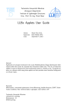
Select any model in the project (e.g., T01 FESTOGarching2color.xmi), rightclick to trigger popup menu. Select Verification → MGSyn: Automatic gamebased synthesis (Figure 5). Then in the MGSyn configuration window (Figure 6),
choose the following options:
8
C.-H. Cheng and M. Geisinger
CB03
CB04
X
Lever 1
a
f
A
RP01
e
Drill01
B
B
HS01
C
C
D
D
D
E
E
A
Level 3,2,1
B
C
F
d
A
RAS01
E
F
F
Y
Lever 2
Lever 3
P4
Processing
CB01
CB02
Storage
Work pieces
Fig. 4. Abstract model for synthesis.
Fig. 5. Invocation of MGSyn from the popup menu of a suitable .xmi model file.
– On the General (Transformation) tab, select Synthesize strategy in high-level
control format.
– On the Output tab, set the File header name to “Result T01”.
– Leave the other options as-is.
– Click on Finish.
It takes a few seconds to calculate the strategy (in intermediate form). When
the execution finishes, refresh the project: select the project MGSynTestcase
from the Package Explorer and press F5. Three files will appear in the model
folder (compare Figure 7).
– Result T01 strategy.txt: automatically synthesized strategy.
– Result T01 domain.pddl: interfaces for components.
– Result T01 problem.pddl: topology, initial condition, specification.
Step 4: Changing the Specification and Resynthesis
In Step 3, the desired specification is as follows:
When the work piece is facing up, drill and store it based on the color.
If it is facing down or the rack is full, then return it to the user.
MGSyn User Manual
9
Fig. 6. Options for synthesis.
This specification is encoded in Planning Domain Definition Language (PDDL).
Listing 1.1 shows and excerpt from the specification.
Now we try to refine the specification:
The object should only be drilled when it is of red color. If it is white,
then just store it on the rack.
Note that since the color sensor is located at the robot arm and the work
pieces are initially at the same position, the winning strategy first has to move
the work piece to the robot arm to detect its color and only then it can be
decided whether or not the object should be drilled. If the color is red, then it
has to be moved back to the drill and then again back to the storage. You might
agree that it would take some time to manually modify the control programs of
the hardware modules to perform this task. With MGSyn, this can be achieved
very quickly.
Open the model (right click the model, and select Open with → Sample
Reflective Ecore Model Editor ) and expand it (similar to Figure 8). In the Formal
Model part, change the Activated field of Property 2) to true and change the
Activated field of Property 1) to false. Execute again Step 3. This time it can
be observed that the generated strategy is slightly more complicated because of
the explanation above.
10
C.-H. Cheng and M. Geisinger
Listing 1.1. Goal specification in PDDL.
(and
; ; O r i e n t a t i o n o f work p i e c e i s known
( or ( f a c e b a l l 1 up ) ( f a c e b a l l 1 down ) )
(and
( or ; ; a → b = ¬a ∨ b
; ; I f work p i e c e i s f a c i n g up , . . .
( not ( f a c e b a l l 1 up ) )
; ; . . . then . . .
(and
; ; . . . ensure i t i s d r i l l e d . . .
( drilled ball1 )
; ; . . . and . . .
(and
( or ; ; a → b = ¬a ∨ b
; ; . . . i f work p i e c e i s red , . . .
( not ( c o l o r b a l l 1 r e d ) )
; ; . . . then . . .
( or
; ; . . . e i t h e r p u t i t t o L1A or L1B . . .
( a t b a l l 1 RAS01−L1A)
( a t b a l l 1 RAS01−L1B)
(and
; ; . . . or i f t h e r a c k i s o c c u p i e d , . . .
(and
( rack−o c c u p i e d RAS01−L1A y e s )
( rack−o c c u p i e d RAS01−L1B y e s )
( not ( rack−o c c u p i e d RAS01−L1A no ) )
( not ( rack−o c c u p i e d RAS01−L1B no ) )
)
; ; . . . move work p i e c e t o CB03−from .
( a t b a l l 1 CB03−from )
)
)
)
; ; A n a l o g o u s l y f o r w h i t e work p i e c e .
...
)
; ; C ol o r o f work p i e c e i s known .
( or ( c o l o r b a l l 1 r e d ) ( c o l o r b a l l 1 w h i t e ) )
)
)
( or ; ; a → b = ¬a ∨ b
; ; I f work p i e c e i s NOT f a c i n g up , . . .
( not ( f a c e b a l l 1 down ) )
; ; . . . then . . .
(and
; ; . . . do NOT d r i l l i t . . .
( not ( d r i l l e d b a l l 1 ) )
; ; . . . and move i t t o CB03−from .
( a t b a l l 1 CB03−from )
)
)
)
)
MGSyn User Manual
11
Fig. 7. Intermediate results of synthesis.
3
Invoking Platform Transformation, Generating
Executable Code and Executing the Simulator
In this section, we describe how users can use MGSyn with accompanied software
packages to perform interactive simulation. Simulation means that the operator
takes control of Environment’s moves, i.e., he or she can feed the sensor readings
to the synthesized program whenever necessary. The total required time for this
experiment is about 10 to 15 minutes if required programs and tools are already
installed. You will need the following:
– CMake: Makefile generator. Since the tool synthesizes executable C/C++
code, CMake3 is used to configure the build environment.
– Perl: Script-based translation of strategies in intermediate form to a C/C++
file. This is a preliminary requirement that might not be needed any more
in future versions of MGSyn. On the Windows platform, you can use ActivePerl4 , on Linux you should already have Perl installed or it is available
as a package for your distribution.
– C/C++ compiler: Compilation of the generated C/C++ code to a native executable. On the Windows platform, we recommend Microsoft Visual C++
2010 Express5 (or Professional). On the Linux platform, we recommend
GCC.
3
4
5
http://www.cmake.org/cmake/resources/software.html#latest
http://www.activestate.com/activeperl/downloads
http://www.microsoft.com/visualstudio/en-us/products/2010-editions/
express
12
C.-H. Cheng and M. Geisinger
Fig. 8. Change the specification.
Step 1: Installation and Setup
Step 1.1: Installing the Interpreter (Simulator) Source Code Download the Interpreter package from our website file folder "MGSyn supplementary
files" and extract it to a folder of your choice. It creates a folder called
interpreter/.
Step 2: Generating Intermediate and Hardware Mapping Code
Select a model within the project (e.g., T01 FESTOGarching2color.xmi), rightclick to trigger popup menu. Select Verification → MGSyn: Automatic gamebased synthesis (Figure 5). Then in the MGSyn configuration window (Figure 6),
choose the following options:
– On the General (Transformation) tab, select Generate architecture script
from model.
– On the Output tab, set the File header name to “new file”.
– Leave the other options as-is.
– Click on Finish.
The engine performs synthesis and creates the following files (compare Figure 9):
1. new file domain.pddl: only used in an intermediate step.
2. new file problem.pddl: only used in an intermediate step.
3. new file strategy.txt: winning strategy that will be translated into a .cpp
file using a Perl script.
4. new file mapping.txt: contains architecture mapping instructions and will
serve as the main() entry point into the simulator program.
MGSyn User Manual
13
Fig. 9. Package Explorer view after creating architecture mapping.
Step 3: Configuring the Interpreter Code
The following steps are not yet integrated into an automatic process. This will
change in future versions of MGSyn.
– Rename the generated new file mapping.txt file to main.cpp and copy it
into the directory where the interpreter source code is located, replacing the
existing main.cpp file.
– Copy the generated new file strategy.txt file to the directory where you
have just copied the main.cpp file to, possibly overwriting the existing file
of the same name.
– Run the script translate.pl located in the directory where the interpreter
source code is located. On the Windows platform, you probably only have
to double-click on the file if you have ActivePerl installed. The same applies
to Linux. If you want to run it from a Linux command line, navigate to the
interpreter directory and run perl translate.pl.
Step 4: Configuring the Build System
Create Visual C++ 2010 solution using CMake:
– Open CMake.
– In the “Where is the source code” field, select the “interpreter” folder
created in Step 1.
– In the “Where to build the binaries” field, select the same folder and append
/build. If it does not exist, CMake later will create it automatically.
14
C.-H. Cheng and M. Geisinger
– Click on Configure. A popup window will ask you to select the target platform. Based on the C++ compiler, select appropriate options. On the Windows platform, choose Visual Studio 10 and leave the rest as-is (Figure 11).
Wait until the configuration process finishes.
– Click on Generate.
– Close CMake.
Fig. 10. Directory settings for CMake.
Step 5: Compile and Run!
– Open Visual C++ 2010 Express (or Professional).
– Select File → Open → Project/Solution.
– Browse the folder interpreter/build, and select the project file MGSyn
(Microsoft Visual Studio Solution).
– On the Solution Explorer (Figure 12), right click on MGSyn, and select Set
as StartUp project.
– Freom the menu, select Debug → Start Debugging. In some cases, the compiler might complain about insonsistent line endings (Figure 12) on the error
list. In this case, double-click the error message, select Yes to resolve the
MGSyn User Manual
15
Fig. 11. Project settings for CMake on the Windows platform.
problem (Figure 13), save all changes and select Debug → Start Debugging
again.
– You should now see the interactive simulator running. In Figure 14, we can
see a typical execution trace for the project T01 FESTOGarching2color.xmi.
See the descriptions on at the bottom of the figure for explanations.
Step 6: Execution on Real Hardware
If you create your own models, you might want to switch between execution on
the real hardware and in the simulator. Switching between these two modes is
done by a single preprocessor define:
– Open the CMakeLists.txt file that is located in the interpreter folder
with a text editor.
– Scroll down to the following line:
set property (TARGET $ {NAME} APPEND PROPERTY
COMPILE DEFINITIONS ”NO ACTUATION” )
This line is enabled by default.
– Comment out the line (by adding a # character at the beginning of the line)
to enable execution on the real hardware or simulation in CIROS Studio.
– Remove the comment character to enable console-based simulation mode
(i.e., the operator can trigger the “control moves” of the environment).
Step 7: Synthesis with Parallelization
MGSyn allows to generate control strategies which trigger multiple actuions simultaneously. This is called parallelization and works as follows: Before calling
16
C.-H. Cheng and M. Geisinger
Fig. 12. Set as StartUp project and fix inconsistent line-endings.
the solver to find a suitable strategy, composed actions are generated from atomic
ones by combining the preconditions and effects of the respective actions (and
adding some constraints). The solver then treats the composed action as if it was
an atomic one. Higher degrees of parallelization can be achieved by combining
more than two actions, respectively.
To use parallelization, select the respective degree from the Parallalization
menu in the MGSyn parameters dialog box (compare Figure 6).
Step 8: Synthesis with Performance Guarantees
We will now perform quantitative synthesis, that is we will restrict the possible
solutions by a certain cost bound. Imagine the following motivating example:
Your automation line has many sensors and actuators, each of them consumes
a certain power when in use (for example, switching on the motor of a conveyor
belt to transport a work piece consumes a certain amount of power). However,
we only have a very limited power supply attached to the system. The interesting
question now is:
Can we synthesize a strategy for a given goal that limits worst case power
consumption such as the power supply is never overloaded?
The answer ist yes, we can. Quantitative synthesis can be used to achieve
this by annotating the model accordingly:
MGSyn User Manual
17
Fig. 13. Resolving the line ending problem.
– Every actuation and sensor triggering needs to be annotated with the amount
of power that it consumes. This is done in the Cost field of the respective behavioral interface definition (e.g., System Model → Hardware Model → Actuation belt-move → right-click → Show Properties View → Cost). Magnitude
of costs should be kept as low as possible while still allowing to distinguish
between costly and non-costly operations. A high worst-case magnitude of
costs requires a large game transition graph and slows down the solver.
– A Quantitative Property needs to be selected and activated (e.g., System
Model → Formal Model → right-click → New Child → Specification Quantitative Property). In the Properties view, adapt the following fields:
• Activated : Change to true and make sure that all other properties have
their Activated value set to false.
• Cost Bound : Define an according cost bound for your goal.
• Main Specification: Define the goal in PDDL. You might want to copy
one from an existing property.
• Parallel Composition: Here you can select the operator that is used to
determine the total cost when two or more actions are performed simultaneously (compare step 8). Since our interpretation of cost in this
example is power consumption, the cost of simultaneous execution of
multiple actions will be the sum of the cost of the individual actions.
Hence, choose SUM.
• Sequential Composition: Here you can select the operator that is used
to determine the total cost when two or more actions are performed
sequentially. Since our interpretation of cost in this example is power
consumption, the cost of sequential execution of multiple actions will be
the maximum of the cost of the individual actions. Hence, choose MAX.
• Type: Set the value to REACHABILITY BOUNDEDCOST (otherwise the
solver will ignore the cost model).
You may now run synthesis on your model. Depending on the selected cost
bound and degree of parallelization (compare step 8), the solver may report
that your specification is feasible (i.e., a strategy is generated) or infeasible (a
strategy containing an error message is generated).
18
C.-H. Cheng and M. Geisinger
Fig. 14. Example simulation trace: an upward facing red work piece is input while the
first position on the rack is occupied by a red work piece. The user, who acts as player
Environment, has specified four sensor inputs to the controller. The first input answers
the question whether the work piece under inspection is faced up or down. Choosing
an input of 0 implies it being faced downwards (face ?obj down), which a choice of
1 implies it being faced upwards (face ?obj up). The three following queries are all
related to the color sensor, where a value of 0 obviously corresponds to a white work
piece (color ?obj white), a value of 1 to a red work piece (color ?obj red) and a value of
3 corresponds to no work piece (!color ?obj white ∧ !color ?obj red). The value 2 should
never occur, since it would correspond to a black work piece. However, since the user
might puts black work pieces into the rack, we handle that case anyway and treat it
as if the rack is occupied (rack-occupied ?room yes), but do not return any color value
for it (!color ?obj white ∧ !color ?obj red).
MGSyn User Manual
4
19
Potential Problems and Fixes
In the following, we list potential problems during installation and their corresponding fixes.
– When an user wants to build the project from source, he/she might encounter
problems due to some inrecognizable texts. The fix is to change the Eclipse
textual encoding (the default encoding may be dependent to the operating
system, such as Chinese version Windows 7). Right click on the project, select
“Properties -> Resources” . Then change the encoding from “inherent
from default” to “ISO-8859-1”. This ensures that contents of the template
can be viewed correctly.
– In the model description, currently it is assumed that all parameters of a
successfully invoked action will be different (It is thus the responsibility
of the designer to ensure this in design). When actions are planned to be
executed in parallel, MGSyn creates additional constructs to specify that
parameters from two control actions should not be the same. There is no
such a constraint when MGSyn composes two environment actions.
– Currently, MGSyn does not offer the translation script to executable for
specifications other than reachability or reachability+safety.
References
1. Eclipse Modeling Framework. http://www.eclipse.org/modeling/emf/.
2. CIROS-Engineering: CIROS Studio. http://www.ciros-engineering.com/en/
products/virtual_engineering/ciros_studio/, 2012.
3. C.-H. Cheng, A. Knoll, M. Luttenberger, and C. Buckl. GAVS+: An open framework
for the research of algorithmic game solving. In Proceedings of the 17th International
Conference on Tools and Algorithms for the Construction and Analysis of Systems
(TACAS’11), volume 6605 of LNCS, pages 258–261. Springer-Verlag, 2011.