1
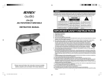
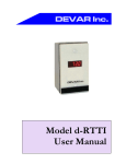
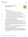
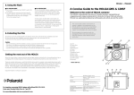
Bosch Phanom
User Manual
Version 0.0. 1
Installation and Operation Manual
1
Bosch Phantom
Table of Contents
1.
2.
3.
4.
Introduction .......................................................................................................................................3
Product Overview ...............................................................................................................................4
Installation .........................................................................................................................................5
Operation .........................................................................................................................................12
Installation and Operation Manual
2
Bosch Phanom
1.
Introduction
The Bosch Phantom meter enables continuous and autonomous measurement of electrical
power consumption and wireless uploading of this information to a cloud-based service for
subsequent analysis and dashboard reporting. Once installed, the device requires no user
intervention or maintenance and will provide years of trouble-free operation in in-door or
out-door environments. It connects to 2 or 3 phase utilities at the breaker box using nonintrusive methods.
Installation and Operation Manual
3
Bosch Phantom
2.
Product Overview
GSM Modem
Central Processor
GSM Antenna
Power
Measurement
CT Connectors
Voltage
Connectors
Power Supply
Connectors
Figure 1 – Interior View
Installation and Operation Manual
4
Bosch Phanom
3.
Installation
3.1. Open the cover
Loosen and remove the 6 screws on the cover. The screws do not need to be removed from
the cover since they are captivated in the cover holes. They only need to be loosened for the
cover to come off.
3.2. Install the SIM card
The SIM card is installed in the holder as follows:
1. Open the SIM card holder (on the PCB between the display and the enclosure wall) by
pushing the metal clip with your finger (see below). It will click.
2. Lift the top portion (hinged) and insert the SIM card with the notch as shown below:
Insert the SIM card
Move the clip up to release
Figure 2a – No SIM card
Figure 2b – Inserting SIM card
3. Close the top portion and snap the metal clip back into position. It will click. (See
below).
Installation and Operation Manual
5
Bosch Phantom
It looks like this if opened.
Close and snap the clip down.
“Click!”
Figure 3a – Open SIM holder
Figure 3b – Closed SIM holder
3.3. Mount the box
If the unit is going to be deployed, this is the time to mount the box. Otherwise, go on to the
next step.
The RF antenna is mounted on the interior upper-right side of the enclosure. It is important
that this wall is not flush with another metal wall so that the RF connection is reliable. Keep a
minimum of 20cm to any metal wall, with more separation being even better. Also, make
sure the unit is mounted outside of any metal cabinets, etc. which will completely block the
RF connection.
Installation and Operation Manual
6
Bosch Phanom
3.4. Electrical Diagram
The connections will be made following this diagram. The three phases are represented by
Red, Yellow and Blue. The Neutral line is Black.
NOTE:
It is very important that the Neutral connection is made to the “Neutral” and “N”
connectors. If this is wired incorrectly the Bosch Phantom unit will be damaged.
Figure 4 – Electrical Connection Diagram
3.5. Install the CT’s
The CT’s are installed on the electrical supply lines between the Breaker and the Load, for
each of the three voltage phases. It is important that they are installed on the wire in the
correct direction or the Phantom meter will report electrical power incorrectly. Follow the
direction arrow on the CT to install it correctly.
It is also important that the correct CT’s are being used with the Phantom meter. Look on the
bottom of the Bosch Phantom meter for the sticker indicating the CT Sensor Rating. Make
sure if it reads “3V out” that the CT’s being used read “250A/3V FULL RANGE”.
Installation and Operation Manual
7
Bosch Phantom
Figure 5 – Bottom Label, CT Sensor Rating
NOTE:
It is very important that the CT’s being used correctly correspond to the one listed on the
Bosch Phantom meter. Using the incorrect ones will damage the meter.
Installation is accomplished by removing the top piece on the CT (has “250 AMP” written on
it) by pulling it apart. There is no retaining clip holding it in, just pull it directly away from the
rest of the CT.
When the CT body is around the utility wire, push and snap the top piece back in place.
Figure 6 -- CT
3.6. Wire the CT’s, Voltage, and Power
To insure immunity to environmental conditions the wires entering the Bosch Phantom
Meter come through a conduit and conduit coupling into the meter. Thus, prior to feeding
the wires into the meter they must be fed through the conduit. It is best to ‘fish’ or pull the
wires through rather than trying to force or push them through since the conduit’s walls are
not smooth.
It may be useful to label the CT’s wires from each of the three phases before pulling them
through the conduit. This is helpful but not necessary.
Installation and Operation Manual
8
Bosch Phanom
Figure 7 – Pulling Wires Through Conduit
When the wires are pulled through the conduit, pull them through the conduit coupling on
the Bosch Phantom meter. Do not push the conduit into the coupling yet since access to the
wires is useful in adding or removing slack or extra wire, and once the conduit it pushed into
the coupling it is very difficult to detach it.
Figure 8 – Pulling Wires Through Conduit Coupler
Connect the CT’s white and black wires as indicated on the connector using the clamp-screws
on the top (loosen them prior to inserting the wire). It is important to connect the A phase
CT (clamped on the Red, #1 wire) to the A phase (Red, #1) CT terminal. If the wires were not
previously labeled the alternative is to gently pull on the CT wires and see which ones pull
inside the Bosch Phantom meter.
Installation and Operation Manual
9
Bosch Phantom
Figure 9 – Connector Block, CT and Voltage
Attach the three voltage phase wires as indicated on the connection diagram according to
the labels on the connectors. Be extra cautious that no strands of the wire are unraveled and
thus outside of the connector which would then create the possibility for a phase-to-phase
short.
Attach the Line, Neutral and Ground connecting wires. These supply power for the Bosch
Phantom meter so when they become ‘live’ the unit will start operating.
Figure 10 – Connector Block, Power Supply
Note: To quick-start the unit and see something on the display the minimum connections
are:
[1] Neutral, [2] Line, [3] N Voltage Terminal, [4] A (or B or C) Voltage Terminal. In this
configuration only Volts will be displayed, for only the phase connected.
Installation and Operation Manual
10
Bosch Phanom
3.7. Plug in the conduit
When the wires are in place and secure, push the conduit into the coupling on the meter. It
has a clip ring which will hold the conduit in place.
3.8. Replace the cover
When the above steps are finished it is necessary to replace the cover for environmental
protection. The six cover screws should be tightened in an alternating pattern, criss-crossing
the corner screws first and then tightening the side screws. Visually confirm from the side
that there are no gaps between the cover and the body of the enclosure and that the seam is
even.
NOTE:
The Bosch Phantom meter is immune to environmental conditions only when the cover has
been installed correctly. Improper cover installation will allow moisture ingress, and if so
the unit will be damaged.
3.9. Confirm operation (on screen)
When the unit powers up, after a short (approx. 20sec) delay the display will show
information like this:
GUID
RF Connection
RF Signal Strength
Memory buffer
usage
Measured Data
Installation and Operation Manual
11
Bosch Phantom
4.
Operation
The Bosch Phantom meter will operate autonomously without any intervention from the
user. The best way to confirm that the unit is installed and operating correctly is to observe
the contents of the display.
4.1. Measurements
Voltage measurements can be validated by observing the values displayed as “VOLTS” and
should be reading the RMS value for the previous display interval. Numbers near zero
indicate a missed connection.
Current measurements are similarly validated by observing the values displayed as “AMPS”.
Again, values are RMS for the previous display interval. Since RMS is an absolute (always
positive) value, negative numbers will never appear so this will not confirm correct
orientation of the CT’s. Numbers near zero indicate no current load, a missing CT, or a
missing connection to a CT.
Power measurements are displayed as “WATTS”. These numbers should be positive if there is
positive power consumption by the location, and negative if the location is generating power.
If there are non-zero Volts and Amps displayed, there will be a non-zero Watts measurement.
Reactive power consumption is displayed as VAR (Volts-Amps Reactive). This is a
measurement of the reactive component of the consumed power. These readings will be
much smaller than Watts and depend on characteristics of the user’s load.
4.2. RF Connectivity
The RF connection through the GSM/GPRS network is validated through the “RF Connection”
and “RF Signal Strength” fields on the display.
RF Signal strength will range from zero to four bars, with more solid bars being better. The RF
connection should be established for 2, 3, or 4 bars, but the installation should be reviewed to
see if there is any adjacent metal walls or partial metal enclosure that can be eliminated to
improve the RF connection.
4.3. Buffer
The Bosch Phantom meter is designed to store data locally in the event of disrupted RF
connectivity, such that it will be re-transmitted when the connection disruption ends. The
data is stored internally in a buffer that has finite size and will fill up if the RF connection is
not re-established within a reasonable time period. The Buffer % shows the status of how
filled the buffer is. While it rarely will display 0%, low numbers are generally good and are
independent confirmation that the RF connection is robust. Numbers near 100% indicate the
need for attention.
Installation and Operation Manual
12