1
GENERAL SPECIFICATION FOR LIFT, ESCALATOR AND PASSENGER CONVEYOR INSTALLATION IN GOVERNMENT BUILDINGS OF THE HONG KONG SPECIAL ADMINISTRATIVE REGION 2012 EDITION ARCHITECTURAL SERVICES DEPARTMENT THE GOVERNMENT OF THE HONG KONG ADMINISTRATIVE REGION PREFACE This General Specification aims to lay down the technical requirements of materials and equipment, the standards of workmanship, the requirements on testing and commissioning as well as requirements on document submissions for lift, escalator, passenger conveyor, powered vertical lifting platform and stairlift installations in government buildings of the Hong Kong Special Administrative Region (HKSAR). The 2012 edition of this General Specification was developed based on its 2007 edition by the Lift and Escalator Specialist Support Group that was established under the Building Services Branch Technical Information and Research & Development Committee of the Architectural Services Department (ArchSD). This new edition comprises revisions in the corrigendum that had been issued for the 2007 edition and, in addition, incorporates updated international standards as well as technological developments which find applications in Hong Kong. To be in line with the department‟s endeavour to reduce the environmental burden on our neighbours and to help preserving common resources while improving the quality of our service, this new edition has continued putting emphasis on green initiatives and initiatives for enhancement of client satisfaction on completed projects. With the benefit of information technology, electronic version of this new edition is to be viewed on and free for download from the Architectural Services Department (ArchSD) Internet homepage. As part of the Government‟s efforts to limit paper consumption, hard copies of this General Specification will not be put up for sale. The draft of this edition has been circulated to stakeholders within and external to the Government before finalization. Nevertheless, the Architectural Services Department welcomes comments on its contents at anytime since the updating of this General Specification is a continuous process for the inclusion of any developments that can help meeting the needs of our community. DISCLAIMER This General Specification is solely compiled for a/an lift, escalator, passenger conveyor, powered vertical lifting platform and stairlift installation carried out for or on behalf of the ArchSD in Government buildings of the HKSAR. There are no representations, either expressed or implied, as to the suitability of this General Specification for purposes other than that stated above. Users who choose to adopt this General Specification for their works are responsible for making their own assessments and judgement of all information contained here. The ArchSD does not accept any liability and responsibility for any special, indirect or consequential loss or damages whatsoever arising out of or in connection with the use of this General Specification or reliance placed on it. The materials contained in this document may not be pertinent or fully cover the extent of the installation in non-government buildings and there is no intimated or implied endorsement of the sales, supply and installation of the materials and equipment specified in this General Specification within the territory of the HKSAR. TABLE OF CONTENTS PART A SECTION A1 SCOPE AND GENERAL REQUIREMENTS SCOPE OF SPECIFICATION A1.1 A1.2 A1.3 A1.4 SECTION A2 STATUTORY OBLIGATIONS AND OTHER REGULATIONS A2.1 A2.2 SECTION A3 Statutory Obligations and Other Requirements Case of Conflict EXECUTION OF WORKS A3.1 A3.2 A3.3 A3.4 A3.5 A3.6 A3.7 A3.8 A3.9 A3.10 SECTION A4 Installation to comply with this General Specification Scope of the Works Terms and Definitions Singular and Plural The International System of Units (SI) Programme of Works Builder‟s Work Coordination of Contract Works Cooperation with other Contractors Site Supervision Sample Board Advice of Order Placed Record of Materials Delivery Protection of Materials and Equipment DRAWINGS AND MANUALS A4.1 A4.2 A4.3 A4.4 Drawings in Electronic Format Installation Drawings As-built Drawings Operating and Maintenance (O&M) Manual and User Manual Table of Contents Page 1 of 16 LF_GS 2012 Edition PART B SECTION B1 GENERAL TECHNICAL REQUIREMENTS GENERAL B1.1 B1.2 SECTION B2 ELECTRICITY SUPPLY AND ELECTRICAL INSTALLATION B2.1 B2.2 B2.3 B2.4 B2.5 B2.6 B2.7 B2.8 B2.9 B2.10 SECTION B3 Works Provided by the Contractor Sound Reducing Finish Service Conditions Stainless Steel Structural Steel REQUIREMENTS RELATING TO ENVIRONMENTAL SUSTAINABILITY B4.1 B4.2 B4.3 B4.4 B4.5 B4.6 B4.7 B4.8 B4.9 SECTION B5 Electricity Supply Works Provided by Electrical Contractor Wiring Equipotential Bonding Travelling Cable Temporary Electricity Supply Emergency Lights for the Control Panels in the Lift Machine Room Batteries And Chargers Suppression of Radio and Television Interference Voltage Dip Operation MISCELLANEOUS B3.1 B3.2 B3.3 B3.4 B3.5 B3.6 SECTION B4 Material and Equipment Workmanship Harmonic Distortion Provision for Future Energy Audit Total Power Factor of Motor Drive Systems Maximum Allowable Electrical Power Maximum Allowable Decoration Load Energy Management of Lift Motor Efficiency Service-on-demand Escalator/Passenger Conveyor Control Compliance with Energy Code REQUIREMENTS FOR LIFT RIDE QUALITY B5.1 B5.2 B5.3 B5.4 B5.5 General Lateral and Vertical Vibration Noise Level Acceleration and Deceleration Jerk Table of Contents Page 2 of 16 LF_GS 2012 Edition PART C SECTION C1 GUIDES AND FIXING C1.1 C1.2 C1.3 SECTION C2 C2.4 C5.2 Normal Terminal Stopping and Final Limit Switches to be Provided Final Limit Switches GUARDING C6.1 C6.2 C6.3 SECTION C7 Suspension Ropes Number of Ropes and Safety Factor Minimum Nominal Diameter Compensating Rope Protection for Traction Sheaves, Pulleys and Sprockets TERMINAL STOPPING AND FINAL LIMIT SWITCHES C5.1 SECTION C6 General Requirements Guide Shoes to be Provided Counterweight Pulleys Guarding SUSPENSION C4.1 C4.2 C4.3 C4.4 C4.5 SECTION C5 Buffers Energy Accumulation Type Buffers Energy Accumulation Type Buffers with Buffered Return Movement Energy Dissipation Type Buffers COUNTERWEIGHTS C3.1 C3.2 C3.3 C3.4 SECTION C4 Steel Guides shall be Used Requirements Guide Brackets BUFFERS C2.1 C2.2 C2.3 SECTION C3 ELECTRIC & HYDRAULIC LIFT General Requirements Partition in Lift Well Counterweight CAR FRAMES C7.1 C7.2 General Requirements Supporting Frame for Goods Lift in Markets and Abattoirs Table of Contents Page 3 of 16 LF_GS 2012 Edition SECTION C8 CAR ENCLOSURES C8.1 C8.2 C8.3 C8.4 C8.5 C8.6 C8.7 C8.8 C8.9 C8.10 C8.11 C8.12 SECTION C9 CONTROL AND INDICATION IN CAR C9.1 C9.2 C9.3 C9.4 C9.5 C9.6 C9.7 SECTION C10 Control Station in Car Additional Control Station Control Station Equipped with Attendant Control Car Direction and Position Indicator Push/Electronic Touch Button Car Top Control Information Display System CAR AND LANDING DOORS C10.1 C10.2 C10.3 C10.4 C10.5 C10.6 C10.7 C10.8 C10.9 C10.10 C10.11 C10.12 C10.13 C10.14 C10.15 C10.16 SECTION C11 Non-combustible Materials to be Used Car shall be Completely Enclosed Platform Loading Internal Construction of Passenger Lift Car Internal Construction of Goods Lift Car in Markets and Abattoirs Internal Construction of Goods Lift Car Internal Construction of Service Lift Car Maintenance Facilities Car Illumination Emergency Lighting Emergency Alarm Device Emergency Exits General Requirements Passenger Lift Bed/Passenger Lift Goods Lift Finishes for Goods Lift in Markets and Abattoirs Vision Panels for Goods Lift with Manually Operated Door Service Lift Electrical Device for Proving the Car Doors Closed Door Operator Landing Door Locking Device Door Locking Devices to be Inaccessible from Landing or Car Door Re-Opening Device „Door-Open‟ Alarm for Manually Operated Doors Emergency Landing Door Unlocking Device and Key Emergency Door in Lift Well Architrave LANDING FIXTURES C11.1 C11.2 C11.3 C11.4 C11.5 Position and Construction Emergency Key Switch for Bed/Passenger Lift Direction and Position Indicator Pre-Arrival Signal for Grouped Passenger Lifts Message Indicator for Passenger Lift Table of Contents Page 4 of 16 LF_GS 2012 Edition SECTION C12 CAR CAPACITY AND LOADING C12.1 C12.2 C12.3 C12.4 SECTION C13 LOAD PLATES, NOTICE BOARDS AND INSTRUCTIONS C13.1 C13.2 C13.3 C13.4 SECTION C14 Provision of Overload Device Operation of Overload Device Full Load Device Floating Car Platform Type Not Acceptable LIFT MACHINERY C16.1 C16.2 C16.3 C16.4 C16.5 C16.6 C16.7 C16.8 C16.9 SECTION C17 Provision of Safety Gear Requirements of Safety Gear Types of Safety Gear Overspeed Governor Operation of the Overspeed Governor Construction of Governor Ropes Breakage or Slackening of Governor Rope Ascending Car Overspeed Protection Means Protection against Unintended Car Movement Protection against Earthquake OVERLOAD DEVICE AND FULL LOAD DEVICE C15.1 C15.2 C15.3 C15.4 SECTION C16 Load Plate shall be Fitted in Car Rated Load shall be Given in Persons and Weight Notice Boards Emergency Release Equipment and Instructions SAFETY GEAR AND OVERSPEED GOVERNOR C14.1 C14.2 C14.3 C14.4 C14.5 C14.6 C14.7 C14.8 C14.9 C14.10 SECTION C15 Passenger Lift Bed/Passenger Lift to be Treated as Passenger Lift Goods Lift Service Lift Lift Motor Bearing and Gear Case Emergency Operation by Manual Device Emergency Operation by Electrical Switch Electro-Mechanical Brake 'RUN/STOP' Switch to be Provided where Lift Equipment is housed in Separate Compartment 'RUN/STOP' Switch to be Provided in Pit Stopping at the Nearest Landing Move to the Nearest Landing after Emergency Stop CONTROLLER C17.1 C17.2 C17.3 C17.4 Construction General Requirements Solid State Controls Provisions for Future Remote Monitoring of Lift Table of Contents Page 5 of 16 LF_GS 2012 Edition SECTION C18 AUTOMATIC CONTROL SYSTEM C18.1 C18.2 C18.3 C18.4 C18.5 C18.6 C18.7 SECTION C19 POWER SYSTEM APPLICATION C19.1 C19.2 C19.3 C19.4 SECTION C20 C20.4 C20.5 Alarm Buzzer/Bell System to be Provided Supervisory Control Panel Intercom System for Passenger, Bed/Passenger and Goods Lifts Telephone Closed Circuit Television FIRE SERVICE REQUIREMENTS C21.1 C21.2 C21.3 C21.4 C21.5 C21.6 C21.7 SECTION C22 Speed at and Below 1.75 m/s Speed above 1.75 m/s Bed/Passenger Lift Hydraulic Lift ALARM BUZZER/BELL SYSTEM, SUPERVISORY CONTROL PANEL, INTERCOM SYSTEM, TELEPHONE AND CLOSED CIRCUIT TELEVISION C20.1 C20.2 C20.3 SECTION C21 Automatic Full Load By-Pass Automatic Push Button Control For Single Lift Down Collective Control for Single Lift („Simplex‟ Control) Down Collective Control for Two Inter-Connected Lifts („Duplex‟ Control) Directional Collective Control for Single Lift Directional Collective Control for Two Inter-Connected Lifts Automatic Group Supervisory Control for 2-8 InterConnected Passenger Lifts Fireman‟s Lift Fireman‟s Switch Home Landing Operation All Lifts To Return To Landing of Designated Point of Entry Upon Actuation of Fire Alarm System Relevant Lifts To Return To Landing of Designated Point of Entry Upon Actuation of Fire Alarm System Refuge Floor Notice REQUIREMENTS FOR BARRIER FREE ACCESS C22.1 C22.2 C22.3 C22.4 C22.5 C22.6 C22.7 C22.8 General Lift Control Buttons Handrail Landing and Car Doors Emergency Alarm Push Button and Intercom Door Jamb Identification Mirror in Accessible Lift Table of Contents Page 6 of 16 LF_GS 2012 Edition SECTION C23 REQUIREMENTS FOR HYDRAULIC LIFT C23.1 C23.2 C23.3 C23.4 C23.5 C23.6 C23.7 SECTION C24 REQUIREMENTS FOR SERVICE LIFT C24.1 C24.2 C24.3 C24.4 C24.5 C24.6 C24.7 C24.8 C24.9 C24.10 C24.11 SECTION C25 Limitation of Use Drive System Hydraulic Machinery Suspension Transfer of Loads to Car Frame Guides Safety Gear Levelling Definition Lift Car and Method of Drive Guide Buffer Counterweight Suspension Safety Gear Load Plate and Warning Notice Car and Landing Door Terminal Stopping Switches Instructions for Emergency Operation REQUIREMENTS FOR MACHINE-ROOM-LESS LIFT C25.1 C25.2 C25.3 C25.4 C25.5 C25.6 C25.7 Definition Statutory Requirements Specific Requirements Control Panel Provisions for Rescue of Passengers Fire Resisting Construction Energy Efficient Lift Table of Contents Page 7 of 16 LF_GS 2012 Edition PART D SECTION D1 ESCALATOR AND PASSENGER CONVEYOR INSTALLATION STEPS/PALLETS D1.1 D1.2 D1.3 D1.4 D1.5 D1.6 D1.7 SECTION D2 STEP/PALLET CHAINS D2.1 D2.2 D2.3 SECTION D3 Landing Plate Landing Gap Tactile Warning Strips COMBS D5.1 D5.2 SECTION D6 Curved Section Straight Section LANDING PLATE D4.1 D4.2 D4.3 SECTION D5 Step/Pallet Chain Materials Quiet Operation TRACKS D3.1 D3.2 SECTION D4 Step/Pallet Demarcation Integral Die-Cast Aluminium Step Tread, Pallet and Step Riser Rollers Traction Dimensions of Step/Pallet Clear Height above Step/Pallet Flat Steps for Escalator Combs Comb Teeth Section BALUSTRADING D6.1 D6.2 D6.3 D6.4 D6.5 Balustrades Dress Guard External Cladding Guard for Adjacent Building Obstacles and Criss-Cross Escalators Distance between Balustrade Interior Panelling Table of Contents Page 8 of 16 LF_GS 2012 Edition SECTION D7 HANDRAILS D7.1 D7.2 D7.3 D7.4 D7.5 D7.6 SECTION D8 TRUSS D8.1 D8.2 D8.3 SECTION D9 AND STEP/PALLET LIGHTS UNDER Footlight Step/Pallet Lights under Landings Replacement of Lamp MOUNTING FACILITIES D13.1 SECTION D14 Electro-Mechanical Brake Auxiliary Brake Handwinding Stopping Distances FOOTLIGHTS LANDINGS D12.1 D12.2 D12.3 SECTION D13 Independent Driving Machine Reduction Gear Motor Speed Bearing BRAKING D11.1 D11.2 D11.3 D11.4 SECTION D12 Lubrication Oil Pan DRIVING MACHINERY D10.1 D10.2 D10.3 D10.4 D10.5 SECTION D11 Construction Step/Pallet Chain Breaking Machinery Space LUBRICATION D9.1 D9.2 SECTION D10 Rubber Handrail Speed Safety Guard Handrail Guide Width of Handrail Handrail Clearance Mounting Facilities SAFETY DEVICES D14.1 D14.2 Safety Device Operation of the Safety Device Table of Contents Page 9 of 16 LF_GS 2012 Edition SECTION D15 CONTROL D15.1 D15.2 SECTION D16 Content Location Metal Cabinet Machinery Space Lighting Switched Socket Outlet Emergency Stop Switch in Machinery Spaces Notice on the Access Door Marking of Escalator/Passenger Conveyor Notice for Automatic Start Notice near Entrances of Escalator/Passenger Conveyor ALARM BUZZER/BELL D18.1 D18.2 D18.3 SECTION D19 of MAINTENANCE FACILITIES AND NOTICES D17.1 D17.2 D17.3 D17.4 D17.5 D17.6 D17.7 SECTION D18 Monitoring CONTROLLER D16.1 D16.2 D16.3 SECTION D17 Control Station Provision for Future Remote Escalator/Passenger Conveyor Alarm Buzzer/Bell Provided by the Contractor Type of Alarm Buzzer/Bell Audio Indicator for Disabled REQUIREMENTS FOR WEATHER-PROOF ESCALATORS OR ESCALATORS IN MARKETS D19.1 D19.2 D19.3 D19.4 D19.5 D19.6 Protection against Weather Protection against Corrosion Lubrication Driving Machine Electrical Wirings and Accessories Drainage Table of Contents Page 10 of 16 LF_GS 2012 Edition PART E SECTION E1 POWERED VERTICAL LIFTING PLATFORM INSTALLATION REQUIREMENTS FOR POWERED VERTICAL LIFTING PLATFORM INSTALLATION E1.1 E1.2 E1.3 SECTION E2 LIFTWELL E2.1 E2.2 E2.3 E2.4 E2.5 SECTION E3 General Requirements for Guides Drive System Hydraulic Control Device OPERATION CONTROL SYSTEM E6.1 E6.2 E6.3 E6.4 E6.5 SECTION E7 Entrance Door/Gate Door/Gate Lock GUIDES AND DRIVE SYSTEM E5.1 E5.2 E5.3 SECTION E6 General Requirements Handrail Emergency Lighting at Platform LANDING DOORS/GATES E4.1 E4.2 E4.3 SECTION E5 General Provisions Materials Lighting Requirements of Different Vertical Rise Travel Lift Pit/Ramp LIFTING PLATFORM CARRIAGE E3.1 E3.2 E3.3 SECTION E4 Definition Statutory Requirements Specific Requirements Control System Landing Control Station Platform Control Station Notice and Marking of Powered Vertical Lifting Platform User Guide and Operation Manual SAFETY DEVICES E7.1 Safety Devices Table of Contents Page 11 of 16 LF_GS 2012 Edition SECTION E8 CALL BELL SYSTEM, SUPERVISORY CONTROL PANEL, INTERCOM SYSTEM AND CLOSED CIRCUIT TELEVISION SYSTEM E8.1 E8.2 E8.3 E8.4 SECTION E9 BATTERY POWERED OPERATION AND FIRE EMERGENCY SERVICE E9.1 E9.2 SECTION E10 Call Bell System to be Provided Supervisory Control Panel Intercom System Closed Circuit Television System Battery Powered Operation Fire Emergency Service REQUIREMENTS FOR WEATHER-PROOF POWERED VERTICAL LIFTING PLATFORM INSTALLATION E10.1 E10.2 E10.3 E10.4 E10.5 Protection against Weather Protection against Corrosion Driving Machine Electrical Wirings and Accessories Drainage Table of Contents Page 12 of 16 LF_GS 2012 Edition PART F SECTION F1 REQUIREMENTS FOR STAIRLIFT F1.1 F1.2 F1.3 F1.4 F1.5 F1.6 F1.7 F1.8 F1.9 F1.10 SECTION F2 F2.3 General Requirements Control & Operation for Attendant-operated Stairlift Installation Control & Operation for Self-operated Stairlift Installation FIRE EMERGENCY SERVICE F3.1 F3.2 SECTION F4 General Technical Features Drive Mechanism Safety Features Display of Information Design Responsibilities Structural Steel Guide Rails Travel Control Electrical Works OPERATION CALL STATIONS F2.1 F2.2 SECTION F3 STAIRLIFT INSTALLATION General Requirements Batteries and Chargers REQUIREMENTS FOR OUTDOOR/WEATHERPROOF TYPE STAIRLIFT INSTALLATION F4.1 F4.2 F4.3 General Requirements Painting Process Welding Table of Contents Page 13 of 16 LF_GS 2012 Edition PART G SECTION G1 INSPECTION, TESTING AND COMMISSIONING DURING CONSTRUCTION PERIOD GENERAL REQUIREMENTS G1.1 G1.2 G1.3 SECTION G2 INSPECTION AND TESTING G2.1 G2.2 G2.3 G2.4 G2.5 SECTION G3 General General Testing and Commissioning Requirements MANDATORY INSPECTION/TEST G4.1 G4.2 SECTION G5 Visual Inspection and Checking Site Tests Factory Tests Factory Test Certificates Functional and Performance Tests TESTING AND COMMISSIONING G3.1 G3.2 SECTION G4 General Labour, Materials and Technical Support Materials and Equipment Delivered to Site General Requirements Test and Examination Certificates HANDOVER INSPECTION G5.1 General Requirements Table of Contents Page 14 of 16 LF_GS 2012 Edition PART H TRAINING, INSPECTION, ATTENDANCE AND OPERATION AND MAINTENANCE DURING MAINTENANCE PERIOD SECTION H1 GENERAL REQUIRMENTS H1.1 H1.2 H1.3 H1.4 SECTION H2 TRAINING OF USERS MAINTENANCE AGENTS H2.1 H2.2 SECTION H3 AND OPERATION AND General Training Schedule, Training Course, On-site Demonstration EMERGENCY SERVICES AND ATTEDANCE TO FAULT CALLS H3.1 H3.2 H3.3 H3.4 SECTION H4 Administrative Requirements Outstanding and Defective Works Keeping of Records Allowance for Inspection General Requirements Attendance to Emergency Services Attendance to Faults and Complaints Reporting of Faults and Repairs INSPECTION, OPERATION REQUIREMENTS H4.1 H4.2 H4.3 H4.4 H4.5 H4.6 AND MAINTENANCE General Requirements Planned Maintenance Statutory Examination and Testing Maintenance Programme and Schedule Examination and Testing Record of Maintenance Final Joint Inspection Table of Contents Page 15 of 16 of Statutory LF_GS 2012 Edition ANNEX IA MAINTENANCE SCHEDULE FOR ELECTRIC PASSENGER, GOODS AND SERVICES LIFTS ANNEX IB MAINTENANCE SCHEDULE FOR HYDRAULIC LIFTS ANNEX IC MAINTENANCE SCHEDULE PASSENGER CONVERYORS ANNEX ID MAINTENANCE SCHEDULE FOR POWERED VERTICAL LIFTING PLATFORMS ANNEX IE MAINTENANCE SCHEDULE FOR STAIRLIFTS ANNEX IIA FORMAT OF LOG BOOK ANNEX IIB NOTES ON ENTRY OF LOG BOOK ANNEX III ARRANGEMENT OF DRAIN WATER STORAGE TANK FOR GOODS LIFT CAR IN MARKET & ABATTOIR ANNEX IV NOTICES NEAR ENTRANCES OF ESCALATOR ANNEX V LIST OF TECHNICAL STANDARDS QUOTED IN THIS GENERAL SPECIFICATION Table of Contents Page 16 of 16 FOR ESCALATORS AND LF_GS 2012 Edition PART A - SCOPE AND GENERAL REQUIREMENTS SECTION A1 SCOPE OF SPECIFICATION A1.1 INSTALLATION TO COMPLY WITH THIS GENERAL SPECIFICATION The lift (passenger, bed/passenger, service and goods), escalator/passenger conveyor, powered vertical lifting platform and stairlift installations shall comply with this General Specification which details the intrinsic properties (including materials and workmanship) of the installation, in so far as it is not overridden by the General Conditions of Contract, Special Conditions of Contract, Particular Specification for the Works, Drawings and/or written instructions of the Architect. A1.2 SCOPE OF THE WORKS This General Specification, Particular Specification, Tender Equipment Schedule and Drawings detail the performance requirements of the Works. The Works to be carried out in accordance with this General Specification shall include the whole of the design, supply and installation of all materials necessary to form a complete installation including any necessary tests, adjustments, commissioning and maintenance as prescribed and all other incidental sundry components together with the necessary labour for installing such components, for the proper operation of the installation. A1.3 TERMS AND DEFINITIONS In this General Specification, the following words or expressions shall have the meanings assigned to them except when the context otherwise requires: A1.3.1 Terms and Definitions Architect The Architect or the Maintenance Surveyor or the Supervising Officer as defined in the Contract. Building Contractor The Contractor employed by the Employer for the execution of the Works as defined in the Contract or the contractor separately employed by the Employer to execute the builder‟s work associated with the Works as appropriate. Section A1 Page 1 of 2 LF_GS 2012 Edition Contract The Contract defined in the General Conditions of Contract for the Works or the Sub-contract defined in the Specialist Sub-contract for the Works or the Subcontract defined in the Nominated Sub-contract for the Works as appropriate. Contractor The Contractor employed by the Employer or the Specialist Sub-contractor employed by the Building Contractor or the Nominated Sub-contractor nominated by the Architect for the execution of the Works as appropriate. Tender The Contractor‟s tender for the Works Contract or the Specialist Sub-contractor‟s tender for the Works Specialist Sub-contract or the Nominated Subcontractor‟s tender for the Works Nominated Subcontract as appropriate. Electrical Contractor The person(s), firm or company whose Tender for the Electrical Works has been accepted by the Employer, and includes the Electrical Contractor's personal representatives, successors, and permitted assigns. Maintenance The maintenance period named in the Annex to Period the Form of Tender commencing on the day following the date of Completion of the Works or any Section or part thereof certified by the Architect in accordance with the Contract. Particular Specification The specifications referred for a particular project. to in the Contract “Construction Plant”, “Contract”, “Contract Sum”, “Drawings”, “Employer”, “Hong Kong”, “Portion”, “Section”, “Site”, “Specification”, “Temporary Works”, “Tender” and “Works” shall have the meanings respectively assigned to them in the General or Special Conditions of Contract. A1.4 SINGULAR AND PLURAL Words importing the singular only also include the plural and vice versa where the context requires. Section A1 Page 2 of 2 LF_GS 2012 Edition SECTION A2 STATUTORY OBLIGATIONS AND OTHER REGULATIONS A2.1 STATUTORY OBLIGATIONS AND OTHER REQUIREMENTS The lift (passenger, bed/passenger, service and goods), escalator/passenger conveyor, powered vertical lifting platform and stairlift installations shall comply with the following: A2.1.1 Statutory Obligations (a) Lifts and Escalators (Safety) Ordinance, Chapter 327, and other subsidiary legislation made under the Ordinance; (b) Security and Guarding Services Ordinance, Chapter 460, and other subsidiary legislation made under the Ordinance; (c) Electrical Ordinance, Chapter 406, and other subsidiary legislation made under the Ordinance; (d) Fire Service (Installations and Equipment) Regulations, Fire Services Ordinance, Chapter 95, and other subsidiary legislation made under the Ordinance; (e) Building (Planning) Regulations and Building (Construction) Regulations, Buildings Ordinance, Chapter 123, and other subsidiary legislation made under the Ordinance; (f) Noise Control Ordinance, Chapter 400, and other subsidiary legislation made under the Ordinance; (g) Water Pollution Control Ordinance, Chapter 358, and other subsidiary legislation made under the Ordinance; (h) Air Pollution Ordinance, Chapter 311, and other subsidiary legislation made under the Ordinance; (i) Ozone Layer Protection Ordinance, Chapter 403, and other subsidiary legislation made under the Ordinance; (j) Waste Disposal Ordinance, Chapter 354, and other subsidiary legislation made under the Ordinance; (k) Environmental Impact Assessment Ordinance, Chapter 499, and other subsidiary legislation made under the Ordinance; (l) Waterworks Ordinance, Chapter 102, and other subsidiary legislation made under the Ordinance; Section A2 Page 1 of 5 LF_GS 2012 Edition A.2.1.2 (m) Dangerous Goods Ordinance, Chapter 295, and other subsidiary legislation made under the Ordinance; (n) Places of Public Entertainment Ordinance, Chapter 172, and other subsidiary legislation made under the Ordinance; and (o) Building Energy Efficiency Ordinance, Chapter 610. Other Requirements (a) Code of Practice on the Design and Construction of Lifts and Escalators issued by the Electrical and Mechanical Services Department, the Government of the HKSAR; (b) Code of Practice on the Design and Construction of Buildings and Building Works for the Installation and Safe Use of Lifts and Escalators, and the subsequent addendum, issued by the Building Authority, the Government of the HKSAR; (c) Code of Practice for Safety at Work (Lift and Escalator) issued by the Labour Department, the Government of the HKSAR; (d) Code of Practice for Lift Works and Escalator Works issued by the Electrical and Mechanical Services Department, the Government of the HKSAR; (e) Code of Practice for Fire Resisting Construction issued by the Building Authority, the Government of the HKSAR; (f) Code of Practice for Means of Access for Firefighting and Rescue issued by the Building Authority, the Government of the HKSAR; (g) Code of Practice for the Electricity (Wiring) Regulations published by the Electrical and Mechanical Services Department, the Government of the HKSAR; (h) Codes of Practice for Minimum Fire Service Installations and Equipment and Inspection, Testing and Maintenance of Installations and Equipment published by the Fire Services Department, the Government of the HKSAR; (i) Requirements and Circular Letters of the Fire Services Department, the Government of the HKSAR; (j) Circulars on Lifts and Escalators issued by the Electrical and Mechanical Services Department, the Government of the HKSAR; Section A2 Page 2 of 5 LF_GS 2012 Edition (k) Code of Practice for Energy Efficiency of Building Services Installations in Building issued by the Electrical and Mechanical Services Department, the Government of the HKSAR; (l) Code of Practice for Energy Audit in Buildings issued by the Electrical and Mechanical Services Department, the Government of the HKSAR; (m) General Requirements for Electronic Contracts, (Specification No. ESG01) – Electronic Division, Electrical and Mechanical Services Department, the Government of the HKSAR; (n) General Specification for Monochrome and Colour Closed Circuit Television System, (Specification No. ESG14) Electronic Division, Electrical and Mechanical Services Department, the Government of the HKSAR; (o) General Specification for Electrical Installation in Government Buildings of the Hong Kong Special Administrative Region, issued by the Architectural Services Department, the Government of the HKSAR; (p) General Specification for Air-conditioning, Refrigeration, Ventilation and Central Monitoring and Control System Installation in Government Building of the Hong Kong Special Administrative Region, issued by the Architectural Services Department, the Government of the HKSAR; (q) Design Manual: Barrier Free Access 2008 published by the Buildings Department, the Government of the HKSAR; (r) The relevant electricity supply company‟s regulations and requirements; (s) Code of Practice on Wind Effects in Hong Kong 2004, issued by the Buildings Department, the Government of the HKSAR; (t) Code of Practice for the Structural Use of Steel 2005, issued by the Building Authority, the Government of the HKSAR; (u) ISO 9386-1:2000, „Power-operated lifting platforms for persons with impaired mobility – Rules for safety, dimensions and functional operation – Part 1 : Vertical lifting platforms‟; (v) BS6440:1999, „Powered Lifting Platforms for Use by Disabled Persons‟; (w) ASME A18.1:2008, „Safety Standard for Platform Lifts and Stairway Chairlifts‟; (x) GB50011-2008, „Code for Seismic Design of Buildings‟ where seismic design consideration is required; and Section A2 Page 3 of 5 LF_GS 2012 Edition (y) A2.1.3 Relevant International Standards and International Codes of Practice. Safety Requirements (a) Lift and Escalators (Safety) Ordinance, Chapter 327, and other subsidiary legislation made under the Ordinance; (b) Occupational Safety and Health Ordinance, Chapter 509, and other subsidiary legislation made under the Ordinance; (c) Factories and Industrial Undertakings Ordinance, Chapter 59, and other subsidiary legislation made under the Ordinance; (d) Public Health and Muncipal Service Ordinance, Chapter 132, and other subsidiary legislation made under the Ordinance; (e) Construction Site (Safety) Regulations; (f) Code of Practice on the Design and Construction of Buildings and Building Works for the Installation and Safe Use of Lifts and Escalators issued by the Building Authority, the Government of the HKSAR; (g) Code of Practice for Safety at Work (Lift and Escalator) issued by the Labour Department, the Government of the HKSAR; and (h) Construction Site Safety Manual issued by the Environmental, Transport and Works Bureau, the Government of the HKSAR. Section A2 Page 4 of 5 LF_GS 2012 Edition A2.1.4 Technical Standards BS, BS EN, EN, ISO, IEC Standards and Codes of Practice, etc. shall be deemed to include all amendments, revisions and standards superseding the standards listed herein, which are current at the closing date of the tender of the Contract unless otherwise specified or unless the latest amendments are not allowed or approved by the relevant authorities under the statutory regulations. Equivalent International Standards may be used if approved by the Architect. A summary of technical standards quoted in this General Specification to which the Works shall comply is listed in Annex V. Materials, equipment and products that comply with equivalent technical standards and demonstrated to be equivalent in overall technical substitute on the type of construction, functions, performance, general appearance and standard of quality of manufacture to the standards and requirements listed herein may be submitted to the Architect for consideration and approval. A2.2 CASE OF CONFLICT The documents forming the Contract are to be taken as mutually explanatory of one another but in case of ambiguities or discrepancies the same shall be explained by the Architect who shall issue to the Contractor instructions clarifying such ambiguities or discrepancies. Section A2 Page 5 of 5 LF_GS 2012 Edition SECTION A3 EXECUTION OF WORKS A3.1 THE INTERNATIONAL SYSTEM OF UNITS (SI) The International System of Units (System International d‟Unites) of weights and measures shall be used for all materials, equipment and measurements. A3.2 PROGRAMME OF WORKS The Contractor shall submit to the Architect a detailed programme of the Works within 4 weeks from the acceptance of his Tender showing the intended method, stages and order of work execution in coordination with the building construction programme, together with the duration he estimated for each and every stage of the Works. The programme shall include at least the following: (a) Dates for the placement of orders for equipment and materials; (b) Expected completion dates for builder‟s works, i.e. when work site needs to be ready; (c) Delivery dates of equipment and materials to Site; (d) Dates of commencement and completion of every stage of the Works in line with the building construction programme, i.e. each floor level and/or zone area; (e) Dates of documents/drawings submissions to relevant Government departments to obtain the necessary approvals; (f) Dates of requirement of temporary facilities necessary for testing & commissioning, e.g. electricity supply, water and town gas; (g) Dates of completion, testing and commissioning; and (h) Short term programmes showing the detailed work schedules of coming weeks and months shall also be provided to the Architect. Programmes shall be regularly updated to reflect the actual progress and to meet the Contractors‟s obligations under the Contract. In addition, detailed submission schedules for installation drawings, equipment and testing and commissioning shall be submitted to the Architect for approval. The formats and information to be included in the schedules shall be as required by the Architect. Section A3 Page 1 of 7 LF_GS 2012 Edition A3.3 BUILDER’S WORK The following builder‟s work in connection with lift, escalator, passenger conveyor, powered vertical lifting platform and stairlift installation as shown in the Drawings will be carried out as part of the building works by the Building Contractor at the expense of the Employer provided that the Contractor has submitted full details of such requirements within a reasonable time to the Architect for approval, so that due consideration may be given before the Building Contractor commences the building works in accordance with the building programme in the areas concerned: (a) Construction of the lift well and enclosures with pit and machine room in accordance with the Drawings; (b) Construction of the escalator/passenger conveyor pits, wells and concrete supporting beams in accordance with the Drawings; (c) Provision of necessary holes, chases, openings, plinths, vents; (d) Provision and fixing steel joists and scaffoldings required for the hoisting of lift/escalator/passenger conveyor machinery and accessories; (e) Provision of concrete fill and/or grouting in for architraves, landing door frames, sills and associated safety guard, etc.; (f) Provision of structural steelwork for lift machinery in lift machine room; (g) For multiple wells, provision of shaft dividing steelwork for supporting guide brackets, etc. and inter-well screens; (h) Provision of openings with adequate size in the floor on both landings of escalator/passenger conveyor; (i) Provision of concrete supporting beams at both landings and the intermediate support if required by escalators with a large vertical rise; (j) Provision of drain outlet and/or sump pit in lift/escalator pit, where specified; (k) Construction of the lift enclosure with pit for powered vertical lifting platform in accordance with the Drawings; (l) Provision of opening to open air for ventilation of the lift shaft for powered vertical lifting platform, where specified; and (m) Provision of pit/ramp and drainage for powered vertical lifting platform, where specified. Section A3 Page 2 of 7 LF_GS 2012 Edition After obtaining the said approval of the Architect, the Contractor is required to mark out at the relevant locations of the Site the exact positions and sizes of all such works and to provide detailed information of such works to the Building Contractor to facilitate him to carry out the builder‟s work as the works proceed. All „cutting-away‟ and „making-good‟ as required to facilitate the Contractor‟s works will be carried out by the Building Contractor, except for minor provisions required for the fixing of screws, raw plugs, redhead bolts, etc. which shall be carried out by the Contractor. The Contractor shall mark out on Site and/or supply drawings of all cutting-away to the Building Contractor within a reasonable time. All expenses properly incurred and losses suffered by the Employer as a result of the Contractor‟s failure to comply with the above requirements are recoverable by the Employer from the Contractor. The Contractor shall ensure that such works are essential for the execution of the Works. In the event that any of such works is proved to be non-essential, unnecessary and/or abortive, the Contractor shall bear the full cost of such works including but not limited to any unnecessary or incorrect cutting-away and making-good and shall reimburse the Employer for all cost incurred in this connection. Upon completion of the builder‟s works by the Building Contractor, the Contractor shall forthwith check and examine that all builder‟s works so executed have been completed in accordance with his requirements. If at any time it becomes apparent to the Contractor that any builder‟s works completed by the Building Contractor does not comply with his requirements in any respect whatsoever, the Contractor shall forthwith give notice in writing to the Architect and specify in details the extents and effects of such non-compliance in that notice. The Contractor is deemed to have satisfied with the builder‟s works after a period of 14 days from the date of completion of the builder‟s works if the above notice is not served to the Architect within such period. All additional expenditure properly incurred and all loss suffered in this connection by the Employer in having such works re-executed and rectified shall be recoverable by the Employer from the Contractor. Section A3 Page 3 of 7 LF_GS 2012 Edition A3.4 COORDINATION OF CONTRACT WORKS The Contractor shall coordinate the Works with those works of the Building Contractor and any other contractors and sub-contractors. The Contractor shall note that the Drawings supplied to him only indicate the approximate locations of the works. He shall make any modification reasonably required of his programme, work sequence and physical deployment of his works to suit the outcome of work coordination or as necessary and ensure that all cleaning, adjustment, test and control points are readily accessible while keeping the number of loops, cross-overs and the like to a minimum. The Contractor shall pay particular attention to the building works programme and shall plan, coordinate and programme his works to suit and adhere to the building works in accordance with the building programme. Any significant problems encountered during the coordination work, which are beyond the Contractor‟s control shall promptly be reported to the Architect. A3.5 COOPERATION WITH OTHER CONTRACTORS The Contractor shall cooperate at all times with the Building Contractor and all other contractors and sub-contractors in order to achieve efficient workflow on Site. Any significant problems beyond the Contractor‟s control shall promptly be reported to the Architect. A3.6 SITE SUPEVISION The Contractor shall keep on the Site a competent and technically qualified site supervisor to control, supervise and manage all the Works on Site. The supervisor shall be vested with suitable powers to receive instructions from the Architect. The site supervisor shall be technically competent and have adequate site experience for the Works. The Contractor shall also refer to the Particular Specification for other specific requirements, if any, on site supervision. Approval by the Architect shall be obtained prior to the posting of the supervisor on Site. The Contractor shall immediately replace any site supervisor whose experience, skill or competency is, in the opinion of the Architect, found to be inadequate for the particular work. Section A3 Page 4 of 7 LF_GS 2012 Edition A3.7 SAMPLE BOARD Within 6 weeks of the acceptance of his Tender and prior to the commencement of Works, the Contractor shall submit to the Architect for approval in good time a sample board of essential components proposed to be used in the Contract. However, the Contractor may request the Architect in writing for an extension of time, if 6 weeks are practically insufficient. Items displayed shall be deemed to be adequate for the Works unless otherwise clearly indicated. Each sample, with clear numbering and labelling, shall be firmly fixed onto a rigid wooden or metal board. A list shall also be affixed on the sample board to show the item description, make and brand, country of origin and locations of installation (if not generally used). Samples rejected by the Architect shall be replaced as soon as possible. Upon approval of all items, the Architect will endorse the list on the sample board and the Contractor shall deliver the board to the site office for reference. The board shall contain samples of all „compact‟ sized materials and accessories to be used in the Works. Written approval of all samples and technical details shall be obtained from the Architect before commencement of any installation work. In the context of this General Specification the term „compact‟ means any item that will fit into a 300 mm cube. The following items shall be included in the sample board as a minimum. Additional items may be required by the Architect and/or specified in the Particular Specification. (a) (b) (c) (d) (e) (f) (g) A3.8 Lift car direction indicator ; Lift car position indicator; Control station to be installed inside a lift car; Call buttons to be installed at lift lobbies; Finishing materials to be adopted inside a lift car; Finishing materials to be adopted for car doors and landing doors; and Colour chart. ADVICE OF ORDER PLACED The Contractor shall submit copies of all orders placed for major items of equipment and materials to the Architect for record. Section A3 Page 5 of 7 LF_GS 2012 Edition A3.9 RECORD OF MATERIALS DELIVERY All materials delivered to Site shall be accurately listed and recorded in the site record books maintained by the representatives of the Architect on Site. Materials and equipment delivered to Site and paid for in interim payment shall be the Employer‟s property. Such materials and equipment shall not be removed from Site without the approval of the Architect in writing and appropriate deduction shall be made in the next interim payment in accordance with the Contract. Where the Building Contractor is in overall control of the Site, the Building Contractor may also be required to record details of all incoming/outgoing materials. In this case, the Contractor shall comply with the Building Contractor‟s arrangements. A3.10 PROTECTION OF MATERIALS AND EQUIPMENT Unless the responsibility is clearly defined in the Contract that the protection on Site for delivered equipment, materials and installation is solely by other contractors, the Contractor shall be responsible for the safe custody of all materials and equipment as stored or installed by him until finally inspected, tested and accepted. In addition, the Contractor shall protect all works against theft, fire, damage or inclement weather and carefully store all materials and equipment received on Site but not yet installed in a safe and secure place unless otherwise specified. All cases of theft and fire must immediately be reported to the police, the Building Contractor, the Architect and the Architect‟s representatives on Site with full details. Where necessary the Contractor shall provide lockable steel container or other equally secure enclosures placed within a securely fenced-in compound provided by the Building Contractor on Site for the storage of materials and equipment. The Contractor shall co-ordinate and arrange with the Building Contractor who shall provide clean, reasonably finished and lockable secure accommodation for the storage of sensitive and/or expensive items before installation. If there is no Building Contractor, all the storage facilities and spaces shall be provided by the Contractor. A3.11 LABEL SCHEDULE The Contractor shall submit to the Architect a Label Schedule, showing all labels, notices, identifications and instructions in full-scale for approval prior to placing of orders. Section A3 Page 6 of 7 LF_GS 2012 Edition All labels, notices, identifications and instructions shall be bilingual in English and Chinese. The Contractor shall follow the Chinese translations from the “Glossaries of Terms Commonly Used in Government Departments” in determining the Chinese translations of specific terms to be adopted for the labels, notices, identifications and instructions. . Section A3 Page 7 of 7 LF_GS 2012 Edition SECTION A4 DRAWINGS AND MANUALS A4.1 DRAWINGS IN ELECTRONIC FORMAT The Contractor shall provide drawings in electronic format as required in the following clauses. These drawings shall conform to the latest version of CAD Standard for Works Projects (CSWP) as posted in the web site of the Works Branch, Development Bureau and in accordance with the latest version of CAD Manual for Architectural Services Department Projects. Should any technical conflict between the CSWP and the CAD Manual arise, the CSWP shall take precedence. A4.2 INSTALLATION DRAWINGS A4.2.1 Drawing Submission Schedule The Contractor shall submit a detailed installation drawing submission schedule and programme to the Architect. The Contractor shall allow reasonable time in the programme for vetting of the installation drawings by the Architect and for drawing resubmissions as necessary. The Contractor shall submit to the Architect a comprehensive "Submission Schedule" of installation drawings and builder‟s work drawings within 2 weeks after the acceptance of Tender, taking into account of the overall programme of the Works including any Specialist Works and works by the utility undertakings. No equipment shall be delivered to the Site and no work shall be executed until the installation drawings have been approved by the Architect. The Contractor shall ensure that installation drawings and builder‟s work drawings are progressively submitted in accordance with the approved "Submission Schedule". The Contractor shall provide at least 6 hard copies and one electronic copy, unless otherwise specified in the Contract, of the approved installation drawings to the Architect for distribution. A4.2.2 Size of Installation Drawings Drawings submitted by the Contractor shall only be of standard sizes from A0 to A4 or B1 size as stipulated in ISO 5457:1999. Section A4 Page 1 of 13 LF_GS 2012 Edition A4.2.3 Contents of Installation Drawings The Contractor shall ensure all installation drawings are accurate representation of the Works, before submitting them to the Architect. All installation drawings shall be fully dimensioned and suitably scaled showing construction, sizes, weights, arrangements, operating clearances and performance characteristics. Before putting any work in hand, the Contractor shall submit additional drawings providing relevant information on the following, where appropriate: A4.2.4 (a) Equipment; (b) Power and ventilation requirements; and (c) General illustration and finish of the lift, escalator, passenger conveyor, powered vertical lifting platform installation and stairlift. Builder‟s Work Drawings Unless otherwise approved by the Architect, the Contractor shall submit to the Architect in accordance with the approved “Submission Schedule”, 6 copies of drawings showing details of all builder‟s work required e.g. the weight and the load on each support of equipment. Such drawings shall clearly indicate the details and positions of all openings, trenches, ducts and cutting required and construction details for plinths and equipment bases and all other requirements in relation to: (a) Lift Installation (i) Lift machine room/lift equipment room and associated equipment, including sub-floor where appropriate; (ii) The arrangement of scaffolding required in the lift well for the installation of the equipment; (iii) All structural openings, such as landing entrances (including structural dimensions), openings, etc.; (iv) All bases, plinths, channels, holes, grouting-in of fixings, etc.; (v) Lifting beams or other facilities for supporting lifting tackle in the machine room and lift well; (vi) Permanent means of access to the lift pit; (vii) Suitable locations of luminaires for machine room and Section A4 Page 2 of 13 LF_GS 2012 Edition lift well lighting; (viii) Guard rails in the machine room; (b) (c) (ix) Hoisting facilities and access required for delivery of equipment to the machine room etc., showing the loading and size of the largest single piece of equipment; (x) Details of structural steelwork for lift machinery in the lift machine room; (xi) Details of shaft dividing steelwork for supporting guard brackets etc., and inter-well screens for multiple wells; and (xii) Method of fixing guide rails. Escalator/Passenger Conveyor Installation (i) Escalator/Passenger Conveyor pits and associated equipment; (ii) End supports including escalator layout; (iii) Hoisting facilities and access, which should contain similar information as that required in Clause A4.2.4 (a)(ix); (iv) Openings with adequate size in the floor on both landings of escalator/passenger conveyor; and (v) Concrete supporting beams at both landings and the intermediate support if required by escalators with a large vertical rise. Powered Vertical Lifting Platform Installation (i) Lift enclosure with pit; (ii) Opening to open air for ventilation of the lift shaft; (iii) Powered Vertical Lifting Platform pit/ramp and associated equipment; and (iv) Hoisting facilities and access, which should contain similar information as that required in Clause A4.2.4 (a)(ix). Section A4 Page 3 of 13 LF_GS 2012 Edition (d) A4.2.5 Stairlift Installation (i) Path of flight, stairway dimensions and landing levels; (ii) Details of structural steelwork on stairway; (iii) Method of fixing guide rails; and (iv) Clear height above stairlift platform. Manufacturer‟s Shop Drawings The manufacturer‟s shop drawings are drawings for equipment or plant to be manufactured by a specialist manufacturing supplier in their own workshops and places away from the Site. The drawings shall show detailed construction, principal dimensions, weights and clearances for maintenance, etc. Immediately after placing of any order or at any event within 4 weeks unless otherwise approved in writing by the Architect, the Contractor shall forward to the Architect for comment, 4 copies of manufacturer‟s shop drawings indicating detailed construction, principal dimensions and weights, clearances for withdrawals and/or cleaning, etc. No work shall proceed on or off Site unless drawings requiring approval are so approved in writing by the Architect. A4.3 AS-BUILT DRAWINGS A4.3.1 Submission of As–built Drawings The Contractor shall submit 3 sets of the first draft prints of as-built drawings within 28 days of the issuance of the certification of completion to the Architect for checking. The Architect after checking the above draft prints shall return one set of the marked up copies of these as-built drawings to the Contractor within 42 days from the date of submission of the Contractor‟s draft prints with comments. The Contractor shall within a further 28 days from the date of receiving the Architect‟s comments on the draft as-built drawings re-submit to the Architect for his approval another 3 sets of the second draft prints of as-built drawings with the Architect‟s comments incorporated. This process of submission and approval shall continue until the final approval of the Architect on these asbuilt drawing is obtained. The final approved as-built drawings shall be in 3 sets of hard copy and 3 sets of electronic copies. These shall be submitted within 21 days from the date of final approval. Each electronic copy shall be in the form of CD-ROM, labelled, with cross reference to a printed list of files explaining the contents and purpose of each file and supplied in sturdy plastic containers. Section A4 Page 4 of 13 LF_GS 2012 Edition The detailed requirements and the media of as-built drawings set out in the Preliminaries of the Bills of Quantities or the Specification Preliminaries shall be followed as appropriate. A4.3.2 Size of As-built Drawings As-built drawings shall only be of standard sizes of A0, A1 or B1 sizeas as stipulated in ISO 5457:1999. Smaller size (A2 to A4) is accepted for installation drawings. A4.3.3 Content of As-built Drawings The Contractor shall ensure all as-built drawings are accurate representation of the Works, before submitting them to the Architect. The as-built drawings required to be provided by the Contractor for various types of BS/E&M installations shall include, but not limited to the following: (a) Building services layout plans such as ducting arrangement, trunking arrangement, piping arrangement, etc.; (b) System schematic diagrams, control diagrams and wiring diagrams; (c) Concealed works layout plan such as concealed conduit routing, etc.; and (d) Installation details and assembly drawings such as LV cubicle switchboard layout, motor control cubicle layout, etc. Section A4 Page 5 of 13 LF_GS 2012 Edition A4.4 OPERATION AND MAINTENANCE (O&M) MANUAL AND USER MANUAL A4.4.1 General The Contractor shall provide two types of manuals to the Architect with all changes made to the installation during the course of the Contract suitably incorporated. The O&M Manual is for use by the maintenance agent of the completed installation. It shall contain detailed technical information covering both operation and maintenance aspects of the installation. The User Manual seeks to give users of the completed installation an overview of the essential information of the installation. The contents of the manual should be concise and succinct for ease of comprehension by people with a non-technical background. A4.4.2 Presentation All manuals shall be written in English, unless otherwise specified. The text of descriptive parts shall be kept concise while at the same time ensure completeness. Diagrammatic materials shall also be supported by comprehensive descriptions. The manuals shall comprise A4 size loose-leaf, where necessary, A3 size folded loose-leaf. The loose-leaves shall be of good quality paper that is sufficiently opaque to avoid “show-through”. Unless otherwise specified in the Contract, the manuals shall be bound in durable loose-leaf four ring binders with hard covers. The manuals shall have labels or lettering on the front cover and spine. The Architect‟s approval shall be obtained on this at the draft manual stage. The electronic copy of manuals including the technical literatures, shall be in PDF format readable by Acrobat Reader Freeware. A4.4.3 Checking and Approval The Contractor shall submit 3 sets of the first draft of O&M Manuals together with a list of recommended spare parts for one year‟s operation and a list of special tools both complete with prices to the Architect for comment within 28 days of the issuance of the completion certificate. The Contractor shall submit 2 sets of the first draft of the User Manual to the Architect for comment at least 56 calendar days before the date of completion. The Architect will check the drafts and return them to the Contractor within 42 days from the date of submission with comments necessary for a final and approved set of document. The Contractor shall then Section A4 Page 6 of 13 LF_GS 2012 Edition make all necessary amendments to the documents and resubmit them to the Architect within 21 days from the date of receipt of comments. The Contractor shall submit 3 sets of hard copies (one of which shall be the original) and one set of electronic copy of the final approved O&M Manuals in CD-ROM within 21 days from the date of approval by the Architect. The Contractor shall submit 2 sets of hard copies and one electronic copy of the final approved User Manuals in CD-ROM within 21 days from the date of approval by the Architect. A4.4.4 Structure and Content of O&M Manual The detailed requirements, structure and contents of the O&M Manual shall be as specified elsewhere in the Contract and shall include the following information under separate sections where appropriate: (a) Project Information This shall include: Project title, site address, contract no., contract title, contractor/sub-contractor name, address, contact persons and their telephone/fax nos., contract commencement date, substantial completion date and end date of maintenance period. (b) (c) System Description (i) Type(s) of system(s) and equipment installed; (ii) Design criteria, design data and parameters; (iii) Locations of the system and major equipment, and what they serve; (iv) Description of operation and functions of the system and equipment; and (v) General operating conditions, expected performance and energy and resources consumption where applicable. List of Installed Equipment Schedule of all items of equipment and plant stating the location, name, model no., manufacturer's serial or reference no., manufacturer‟s design duties and data. Section A4 Page 7 of 13 LF_GS 2012 Edition (d) (e) Spare Parts and Special Tools Lists (i) List of Spare Parts supplied by the Contractors: Item descriptions, supplied quantities, model nos., manufacturer‟s serial or reference nos. and storage locations. (ii) Recommended Spare Parts List and Special Tools List: Manufacturers‟/suppliers‟ recommendations for spare parts and special tools with item description, unit rate, recommended stock quantities as well as the agents for the spare parts and special tools. Manufacturers‟ Certificates/Guarantees (i) Manufacturers‟ certificates such as factory test certificates, laboratory test reports and guarantees and any others where required for the equipment and plants, etc. (ii) Originals of Statutory Inspection Certificate for various installations, including: - Lifts and escalators (Certificate on Examination of Lift or Escalator and signed forms/certificates as required by the Lifts and Escalators [Safety] Ordinance). [Note: Testing records & commissioning data (other than the types prescribed above), which are required under the Contract such as the T&C procedures, etc to verify the compliance of the BS/E&M system‟s/equipment‟s performance with the contract requirements, are checked and endorsed separately by the Architect and do not form part of the O&M manuals.] (f) Safety Precautions for Operation and Maintenance State, where applicable, hazard warnings and safety precautions of which the operation and maintenance staff need to be aware: (i) mandatory requirements relating to safety; (ii) known hazards against which protection measures shall be taken; and (iii) known features or operational characteristics of the installed equipment or systems which may cause hazard and the related safety precautions. Section A4 Page 8 of 13 LF_GS 2012 Edition (g) Operation Instructions Instructions for the safe and efficient operation, under both normal and emergency conditions, of the installed system which shall comprise: (i) an outline of the operating mode; (ii) control logic and data (sequence, effect, limits of capability, modes and set points); (iii) procedures and sequences for start-up and shut-down; (iv) interlocks between equipment/system; (v) calling on of stand-by equipment; (vi) precautions necessary to overcome known hazards; (vii) means by which any potentially hazardous equipment can be made safe; (viii) estimation of energy consumption and energy costs; (h) (ix) forms for recording plant running hours, energy consumption and energy costs; and (x) operating data such as running current, operating pressure, operating flow rates, etc. Maintenance (i) Maintenance instructions Manufacturers‟ and the Contractor's recommendations and instructions for the maintenance of the installed equipment. Clear distinction should be made between planned tasks (preventive maintenance) and fault-repair tasks (corrective maintenance). Instructions shall be given on each of the following, as appropriate: - nature of deterioration, and the defects to be looked for; isolation and return to service of plant and equipment; dismantling and reassembly; replacement of components and assemblies; dealing with hazards which may arise during maintenance; adjustments, calibration and testing; and special tools, test equipment and ancillary services. Section A4 Page 9 of 13 LF_GS 2012 Edition (ii) Maintenance schedules Proposed maintenance schedules for all the preventive maintenance tasks identified above. The schedules shall be based on both manufacturers' recommendations and other authoritative sources (e.g. statutory or mandatory requirements) and should include: - routine servicing; inspections; tests and examinations; adjustments; calibration; and overhaul. The frequency of each task may be expressed as specific time intervals, running hours or number of completed operations as appropriate. Collectively, the schedules will form a complete maintenance cycle, repeated throughout the whole working life of the installation. (i) (j) Drawing Lists (i) A complete list of as-built drawings identified with drawing number/reference; (ii) A complete list of manufacturers‟ shop drawings with drawing number/reference, where applicable; and (iii) A brief description of CD-ROM for these drawings. Technical Literatures A complete set of manufacturers' literatures for all the plant and equipment installed in the system. The contents of these literatures shall cover the following areas where applicable: (i) description of highlighted; (ii) performance - behavioural characteristics of the equipment; (iii) applications - suitability for use; (iv) factory/laboratory test reports, detailed drawings, circuit diagrams; (v) methods of operation and control; Section A4 Page 10 of 13 equipment with model numbers LF_GS 2012 Edition (vi) operation instructions; (vii) cleaning and maintenance requirements; (viii) plants, materials and space required for maintenance; (k) A4.4.5 (ix) protective measures and safety operation and maintenance; and (x) part lists. precautions for Contact addresses and telephone numbers of suppliers of major equipment Structure and Content of User Manual The detailed requirements, structure and contents of the User Manual shall include, where applicable, the following information: (a) Project Information This shall include: Project title, site address, contract no., contract title, contract commencement date, substantial completion date and end date of Maintenance Period. (b) (c) System Description (i) Type(s) of system(s) and equipment installed, and their purposes; (ii) Locations of major plant rooms and riser ducts; (iii) Brief description of the operation and functions of the systems and equipment; and (iv) Listing of set points which can be adjusted by the user to suit their operation needs. Schedule of Major Plant Rooms and Installed Equipment (i) Schedule of major plant rooms and riser ducts including their locations; and (ii) Schedule of major equipment and plants including their locations and serving areas. Section A4 Page 11 of 13 LF_GS 2012 Edition (d) Safety Precautions for Operation Any safety precautions and warnings signals that the users shall be aware of in the daily operation of the various systems and equipment in the installation including: (e) (i) mandatory requirements relating to safety; (ii) features or operational characteristics of the installed systems or equipment which may cause hazard and the related safety precautions; (iii) protective measures operation; and (iv) list of warning signals and the related meanings that the user shall be aware of and the actions to be taken. and safety precautions for Operation Instructions Instructions for the safe and efficient operation, under both normal and emergency conditions, of the installed system which shall comprise: (f) (i) an outline of the operating mode; (ii) step by step operation instructions for systems and equipment that are to be operated by the user, including at least procedures for start-up and shut-down; (iii) means by which any potentially hazardous situation can be made safe; and (iv) cleaning and basic maintenance procedures. List of Statutory Periodic Inspections and Tests A schedule of periodic inspections and tests that owner and/or user of the installation have to arrange to achieve compliance with the requirements stipulated in the relevant Laws of Hong Kong. The frequency of such inspections and tests shall be expressed in specific time intervals. (g) Drawings A set of selected as-built drawings which shall be able to illustrate to the user the general layout of the completed installation. Section A4 Page 12 of 13 LF_GS 2012 Edition (h) Photographs A set of photographs with suitable captions to illustrate to the user the appearance and locations of devices which require their setting and operation. A4.4.6 Intellectual Property Rights The Government shall become the absolute and exclusive owner of the Operation and Maintenance Manuals and the User Manual and all intellectual property rights subsisting therein free from all encumbrances. In the event that the beneficial ownership of any intellectual property rights subsisting in the above Manuals are vested in anyone other than the Contractor, the Contactor shall procure that the beneficial owner shall grant to the Employer a transferable, non-exclusive, royalty-free and irrevocable licence (carrying the right to grant sub-licences) to utilize the intellectual property rights in the manuals for the purposes contemplated in the Contract. For the avoidance of doubt such purposes shall, but not limited to, include providing free copying of the materials in the manuals by any subsequent owner or user of the installation, and/or any party responsible for the operation and maintenance of the installation in connection with any subsequent alteration, extension, operation and maintenance of the installation. Section A4 Page 13 of 13 LF_GS 2012 Edition PART B - GENERAL TECHNICAL REQUIREMENTS SECTION B1 GENERAL B1.1 MATERIAL AND EQUIPMENT All materials, equipment and installation works shall be carried out by adoption of the best available quality materials and workmanship and shall, where applicable, comply with the latest edition of the appropriate standards and/or codes of practice and as specified in this General Specification. This requirement shall be deemed to include all amendments to these standards and codes up to the date of tendering. Selection of materials and equipment shall be based on this General Specification, the Particular Specification and the technical data contained in the Drawings. Where different components of equipment are interconnected to form a complete system, their characteristics of performance and capacities shall match in order to ensure efficient, economical, safe, reliable and sound operation of the complete system. B1.2 WORKMANSHIP Works shall be carried out in such a manner as to comply with all relevant ordinances, regulations and codes of practices as listed in this General Specification together with any amendments made thereto. Proper tools shall be used for the Works. The installation works shall be in line with the good practice accepted by the local industry and in compliance with this General Specification, the Particular Specification and the Drawings. All tradesmen must be experienced in the trade and the Works carried out shall be consistent with good practice in Hong Kong and to the satisfaction of the Architect. Section B1 Page 1 of 1 LF_GS 2012 Edition SECTION B2 ELECTRICITY SUPPLY AND ELECTRICAL INSTALLATION B2.1 ELECTRICITY SUPPLY Unless otherwise stated in the Particular Specification, the electricity supply for the electrical machinery will be 380V, 3-phase, 50 Hz and the electricity supply for lighting will be 220V, single-phase, 50 Hz. B2.2 WORKS PROVIDED BY ELECTRICAL CONTRACTOR The Electrical Contractor will be responsible for providing the power supply for the electrical equipment. The supply point will be terminated at an isolating switch or switch-fuse at the following location according to the type of installation: (a) Lift installation - lift machine room or near lift controller; (b) Service lift installation - lift machine compartment; (c) Escalator/passenger conveyor installation - escalator/passenger conveyor machinery space; (d) Powered Vertical lifting platform installation - lift machine compartment; and (e) Stairlift - adjacent to stairlift drive cabinet. From the isolating switch or switch-fuse, all electrical works for the lift, escalator, passenger conveyor, powered vertical lifting platform and stairlift installation shall be the responsibility of the Contractor. The Electrical Contractor will provide permanent lighting in the lift well and the machine and pulley rooms, and socket outlets in the machine and pulley rooms and the lift pit. The lighting in the lift well will comprise one lamp positioned at most 0.5 m from the highest and lowest points of the guided travel of the lift car with intermediate lamps at 7 m maximum spacing and controlled by two-way switches located in the machine room and in the lift pit. The socket outlet in the lift pit will be of weatherproof type. The Electrical Contractor will be responsible for the provision of conduit/trunking facilities for the following: (a) from the lift well at the landing of designated point of entry to the position of the supervisory control panel; (b) for the alarm buzzers/bells, call bell system and the supervisory control panel at the landing of designated point of entry between the lift well and the position of the panel; Section B2 Page 1 of 4 LF_GS 2012 Edition (c) for the intercom system linking the lift well to machine room and the caretaker‟s office; (d) for CCTV system inside the lift well and the machine room; and (e) for the telecommunication system such as the emergency telephone system in Clause C20.4 The Contractor shall furnish sufficient information to the Architect in good time before the conduit/trunking installation work is commenced on site. The Contractor shall be liable for all expenses incurred due to his failure to comply with the above requirement. B2.3 WIRING All cables, trunkings, conduits and conduit fittings necessary for the circuits (including power, lighting and control circuits) shall be installed in accordance with the General Specification for Electrical Installation in Government Buildings of the Hong Kong Special Administrative Region and the Code of Practice for the Electricity (Wiring) Regulations. All wiring installed in the lift machine room and lift well, other than travelling cables, shall be enclosed in galvanized steel conduits or trunkings. The Contractor shall supply, install and commission all electrical wiring installation as required for completion of the work which shall include all necessary suitably sized cables and wiring from the electrical power isolator. Labels and identifications for electrical installation shall comply with the General Specification for Electrical Installation in Government Buildings of the Hong Kong Special Administrative Region. B2.4 EQUIPOTENTIAL BONDING Equipotential bonding of minimum of 2.5 mm2 single core sheathed copper protective conductor shall be provided to all conductive parts including guide rail, support rail, control panel, supporting structural framework etc. A 2.5 mm2 single core sheathed copper protective conductor shall link between the incoming isolator, and driving motor. All conductive parts of the plant and equipment, other than those forming part of an electrical circuit, shall be effectively connected onto the main earthing system. Every complete earth loop circuit including conduits, cable sheaths, core conductors and transformer windings shall be tested. The impedance value of each loop circuit of the installation shall not exceed 0.5 ohm. Section B2 Page 2 of 4 LF_GS 2012 Edition B2.5 TRAVELLING CABLE Travelling cables between the lift well and lift car terminal boxes shall be suspended by looping over reels or by suitable clamps and terminated at a suitable position that they will not be prone to damage by water seepage. The construction of the travelling cables shall comply with EN 50214:2006 which in general shall fall within the following 5 types of cables: Maximum Speed Limit Maximum Freely Suspended Length Rubber-insulated & sheathed, flexible cable with 4 to 48 cores 1.6 m/s 35 m Rubber-insulated & sheathed, flexible cables with 3 to 18 cores 1.0 m/s 15 m PVC-insulated, and sheathed, flexible cables with 4 to 72 cores No limit No limit PVC-insulated and sheathed, flexible cables with 3 to 24 cores 1.6 m/s 35 m Rubber-insulated, flexible cables with 36 to 72 cores having strain - bearing centre No limit No limit Type Remark Higher limits permissible if strain - bearing material is included Higher limits permissible if strain - bearing material is included Travelling cables shall be hung in the lift well, suspended from one end only, for sufficient time to avoid twisting or kinking before making final connections. Facility shall be provided on both car and well cable anchorages to permit each cable to be rotated to counter accumulated twist. Cables with 12 or more cores shall be used, and all cables that are to be grouped together shall be of the same size unless otherwise approved by the Architect. Section B2 Page 3 of 4 LF_GS 2012 Edition B2.6 TEMPORARY ELECTRICITY SUPPLY Temporary electricity supply during the construction period will be provided by the Building Contractor. B2.7 EMERGENCY LIGHTS FOR THE CONTROL PANELS IN THE LIFT MACHINE ROOM Emergency lights for control panels in the lift machine room of adequate illuminance shall be provided by the Contractor in the lift machine room. The illuminance at each control panel shall be not less than 50 lux. These lights shall be operated by batteries and shall be manually operated by a switch located at a convenient position inside the machine room. B2.8 BATTERIES AND CHARGERS The batteries for each lift, escalator, passenger conveyor, powered vertical lifting platform and stairlift shall be capable of maintaining a supply to the connected emergency load for a minimum period of two hours. The batteries shall be of sealed, high rate maintenance free nickel-metal hydride type, or a type of better functions and performance and approved by the Architect and shall have a guaranteed life expectancy of at least 4 years. They shall not have any memory effect as to affect their usable life or performance. The nickel-metal hydride battery shall comply with EN61951-2:2003 where appropriate. The battery charger shall be compatible with the batteries used. The charger shall comply with EN 60335-2-29:2004 and be capable of fully re-charge the batteries in not more than 12 hours. B2.9 SUPPRESSION OF RADIO AND TELEVISION INTERFERENCE The lift, escalator, passenger conveyor, powered vertical lifting platform and stairlift installations shall be adequately suppressed against radio and television interference to limits as laid down in EN 55014:2006, IEC 60939-1:2005 and IEC 60939-2:2005. Interference suppression components shall not be used in any part of the circuit where their failure might cause an unsafe condition. B2.10 VOLTAGE DIP OPERATION The Contractor shall provide post-voltage-dip-operation means for all lifts to comply with the statutory codes and requirements as stipulated in Circular No. 16/2009 issued by the Electrical and Mechanical Services Department, the Government of the HKSAR in case any lift stops when voltage dip occurs. Also see Clause C16.9. Section B2 Page 4 of 4 LF_GS 2012 Edition SECTION B3 MISCELLANEOUS B3.1 WORKS PROVIDED BY THE CONTRACTOR The following works in connection with the Lift, Escalator, Passenger Conveyor, Powered Vertical Lifting Platform and Stairlift Installation shall be carried out by the Contractor: B3.2 (a) Steelwork other than those mentioned in Clause A3.3, inserts, fixing brackets etc. for fixing the lift machine/equipment in the lift machine room; and (b) Mounting brackets, bearing plates etc. required for the installation of the lift/escalator/passenger conveyor. SOUND REDUCING The whole of the lift, escalator, passenger conveyor, powered vertical lifting platform and stairlift machinery including the opening and closing of the car and landing doors shall be quiet in operation, and sound reducing rubber pads or other means shall be provided by the Contractor where necessary to eliminate vibration and noise transmission. B3.3 FINISH All metal work supplied by the Contractor in out of the way locations such as the lift well, lift pit, machine room and on the outside of the lift car shall be properly wire-brushed, cleaned of rust, scale, dirt and grease prior to the application of one coat of rust inhibiting primer, with particular attention paid to the priming of outer surfaces of car doors, inner surfaces of landing doors, metal work associated with door assemblies, the underside and the framework of lift cars. Any part of the equipment, including guide rails, which requires greasing or oiling and any components that are supplied unpainted by the manufacturers due to functional reasons shall not be painted. All normally visible metal surfaces, other than stainless steel and non-ferrous surfaces, shall be finished with one coat of rust inhibiting primer, one under coat/finishing coat and one finishing coat of enamel paint to a colour to be selected by the Architect. All locally applied paints and primers shall comply with Air Pollution Control (Volatile Organic Compounds) Regulations, Cap 311. Section B3 Page 1 of 2 LF_GS 2012 Edition B3.4 SERVICE CONDITIONS All electrical, electronic and mechanical equipment shall suit the service conditions as stated below: Climate : Hong Kong Temperature range : Minus 5oC to +40oC Average 0oC to 35oC (over 24 hours) B3.5 Relative humidity : 99% maximum Altitude : Sea level to 1000 metres STAINLESS STEEL Unless otherwise specified, stainless steel shall be of EN 10029:1991, EN 10048:1997, EN 10088-1:2005, EN 10095:1999, and ISO 9445:2002 Grade 1.4401 (or Grade 316S31 or Grade AISI 316) or equivalent. B3.6 STRUCTURAL STEEL Structural steel work shall comply with the provisions of BS 7668:2004, EN 10029:1991, EN 10025:2004 and EN 10210:2006 of appropriate grades. All forms of steel used shall be of standard section with dimensions, tolerances and properties complying with BS 4-1:2005 and EN 10210-2:2006. Supplier of structural steel work shall provide mill certificates of the material as required by the Architect. Section B3 Page 2 of 2 LF_GS 2012 Edition SECTION B4 REQUIREMENTS RELATING TO ENVIRONMENTAL SUSTAINABILITY B4.1 HARMONIC DISTORTION The lift/escalator/passenger conveyor installation shall not, by injection of undesirable waveforms into the electricity supply distribution system, adversely affect the power company's system and/or the electricity supply to other users or consumers. The Total Harmonic Distortion (THD) produced by the lift/escalator/passenger conveyor motor drive system measured at the isolator connecting the lift/escalator/passenger conveyor equipment to the feeder circuit of the building is limited to the maximum allowable values specified in Table B4.1–(1) and (2). For lift installation, the THD shall be measured at the moment the lift car is moving up with rated load at its rated speed. For escalator/passenger conveyor installation, the THD shall be measured when the escalator/passenger conveyor is operating with no-load at its rated speed. The Contractor shall be responsible for providing all necessary harmonic filter(s) to bring down the THD to within the maximum allowable values should the THD of the installation exceed the maximum allowable values specified in Table B4.1–(1) and (2). Table B4.1–(1) - Maximum Allowable THD for Lift Motor Drive Systems Circuit Fundamental Current of Motor Drive Maximum THD (%) I< 40A 40A≦I< 80A 80A≦I< 400A 400A≦I<800A 40 35.0 22.5 15.0 Table B4.1–(2) Drive Systems Maximum Allowable THD for Escalator/Conveyor Motor Circuit Fundamental Current of Motor Drive I< 40A Maximum THD (%) 35, for electrical supply direct from building‟s feeder circuit 40A≦I< 80A 80A≦I< 400A Section B5 Page 1 of 12 40, for electrical supply NOT direct from building‟s feeder circuit 35.0 22.5 LF_GS 2012 Edition Total Harmonic Distortion (THD) = I h2 h I 2 1 where B4.2 I1 = r.m.s. value of fundamental current (A) Ih = r.m.s. value of current of the hth harmonic order (A) PROVISION FOR FUTURE ENERGY AUDIT Digital multifunction metering devices or permanent provisions for connection of such devices as shown on the Drawing(s) and/or stated in the Particular Specification shall be provided in all lift, escalator and passenger conveyor installations for the purpose of energy management, monitoring and audit. Accessibility and sufficient space for these devices shall be allowed for. Such devices or provisions shall be provided at each electricity supply feeder for the lift, escalator and passenger conveyor installations, and at the electrical supply circuit for each motor drive in case a feeder supplies more than one lift, escalator or passenger conveyor or a feeder supplies to other auxiliary equipment besides the lift motor drive. The measurements shall include the electrical loads of the motor drives, the auxiliary loads such as ventilation and lightings, voltages (phase-to-phase and phase-to-neutral), currents (line currents and neutral currents), total power factor, energy consumption (kWh), power (kW) and maximum demand (kVA). Unless otherwise specified, digital multifunction metering devices installed in lift machine room or lift equipment room/cabinet or installed after the power supply point of the Electrical Contractor shall be provided by the Contractor. Digital multifunction metering devices shall comply with the General Specification for Electrical Installation in Government Buildings of the Hong Kong Special Administrative Region. The metering device shall be equipped with interfacing hardware facilities and connection ports such as RS232/RS485/Ethernet and shall be able to communicate with a remote display device/system or a PC-based building management system via a common network protocol for reading/logging /recording/analysis/downloading of the energy and performance data recorded, by means of plugging in communication module without further modification of the basic unit. Digital multifunction metering device shall be installed at a location easily accessible by the building management and maintenance staff wherever possible. When digital multifunction metering device is installed at a location not easily accessible by the building management and maintenance staff and there is no indication that a building management system is to be provided within the building for connection to the metering devices, the Contractor shall provide all necessary plugging in communication module and hardware for the digital multifunction metering devices for its ready connection to a future remote device/system. Section B5 Page 2 of 12 LF_GS 2012 Edition In case the metering device for lift, escalator and passenger conveyor installation is specified to be provided by other parties in the Particular Specification or Drawings, the Contractor shall coordinate with relevant parties on the most suitable location(s) for the installation of digital multifunction metering devices. Digital multifunction metering devices and fixed remote display device/system shall be housed in lockable housing(s) or cabinet(s) by the Contractor when they are not placed within a normally locked up area. The connection and removal of the metering devices shall not entail a stoppage or disruption to the operation of the lift, escalator and passenger conveyor installation. B4.3 TOTAL POWER FACTOR OF MOTOR DRIVE SYSTEMS The Total Power Factor of a motor drive circuit measured at the isolator connecting the lift/escalator/passenger conveyor equipment to the building‟s feeder circuit or the power source shall not be less than 0.85. For lift equipment, the Total Power Factor shall be measured when the lift car is carrying a rated load at its rated speed in an upward direction. For escalator/passenger conveyor equipment, the Total Power Factor shall be measured when the motor drive is operating under its brake load condition with rated speed in upward direction. Manufacturer‟s documentation are required to be submitted as proof. Total Power Factor where P (P Q 2 D 2 ) 2 P = active power in kW of fundamental component Q = reactive power in kVAr not including any harmonic component D = distortion power in kVAd contributed from harmonic components Section B5 Page 3 of 12 LF_GS 2012 Edition B4.4 MAXIMUM ALLOWABLE ELECTRICAL POWER (a) Maximum Allowable Electrical Power of Traction Lifts The running active electrical power of the motor drive of traction lift system carrying a rated load at its rated speed in an upward direction shall not exceed the maximum allowable values specified in Table B4.4– (1), (2) and (3). Table B4.4–(1) - Maximum Allowable Electrical Power of Traction Lifts (Vc < 3) Rated Load Maximum Allowable Electrical Power (kW) of Traction Lift Systems for various Ranges of Rated speed (Vc) in m/s (kg) L < 750 750 L <1000 1000 L < 1350 1350 L<1600 1600 L <2000 2000 L < 3000 3000 L < 4000 4000 L < 5000 L ≧ 5000 Table B4.4–(2) - Rated Load (kg) L < 750 750 L < 1000 1000 L < 1350 1350 L<1600 1600 L < 2000 2000 L < 3000 3000 L < 4000 4000 L < 5000 Vc < 1 1 Vc < 1.5 1.5 Vc < 2 2 Vc < 2.5 2.5 Vc < 3 6.7 9.5 11.4 14.3 16.2 23.8 31.4 39.9 0.0079L+ 0.475 9.5 11.4 16.2 19 23.8 35.2 45.6 57 0.0112L+ 0.95 11.4 16.2 20.9 25.7 30.4 44.7 59.9 74.1 0.0148L+ 0.48 15.2 20 25.7 30.4 37.1 56.1 74.1 92.2 0.0180L+ 1.9 17.1 22.8 30.4 36.1 43.7 66.5 87.4 109.3 0.0217L+ 0.475 Maximum Allowable Electrical Power of Traction Lifts (3Vc < 7) Maximum Allowable Electrical Power (kW) of Traction Lift Systems for various Ranges of Rated speed (Vc) in m/s 3 Vc < 3.5 3.5 Vc < 4 4 Vc < 5 5 Vc < 6 6 Vc < 7 20 25.7 34.2 40.9 50.4 75.1 98.8 123.5 21.9 29.5 38 46.6 57 85.5 114 142.5 23.8 30.4 42.8 49.4 61.8 90.3 123.5 152 28.5 37.1 49.4 58.9 71.3 109.3 142.5 180.5 32.3 43.7 57 68.4 83.6 125.4 166.3 209 Section B5 Page 4 of 12 LF_GS 2012 Edition Table B4.4–(3) - Maximum Allowable Electrical Power of Traction Lifts (Vc≧7) Rated Load (kg) L < 750 750 L < 1000 1000 L < 1350 1350 L < 1600 1600 L < 2000 2000 L < 3000 3000 L < 4000 4000 L < 5000 Maximum Allowable Electrical Power (kW) of Traction Lift Systems for various Ranges of Rated speed (Vc) in m/s 7 Vc < 8 37.1 49.4 66.5 78.9 99.8 147.3 194.8 242.3 8 Vc < 9 42.8 57 76 90.3 114 166.3 223.3 275.5 Vc ≧ 9 4.643Vc+0.0013Vc3 6.192Vc+0.002 Vc3 8.357Vc+0.002Vc3 9.905Vc+0.0025 Vc3 12.381Vc+0.0013Vc3 18.572Vc+0.0029Vc3 24.762Vc+0.0036Vc3 30.953Vc+0.0046Vc3 Exception: Lifts with rated speed not less than 9 m/s serving a zone of over 50storey or over 175 m between top/bottom-most landing and principal/ground landing, and designated as fire service lifts or sky lobby shuttles serving two principal stops. (b) Maximum Allowable Electrical Power of Hydraulic Lifts The running active electrical power of the hydraulic oil pump motor of any hydraulic lift system carrying a rated load at its rated speed in an upward direction shall not exceed the maximum allowable values specified in Table B4.4–(4). Table B4.4–(4) - Maximum Allowable Electrical Power of Hydraulic Lifts Maximum Allowable Electrical Power (kW) Under rated conditions Rated Load (kg) 26.6 50.4 71.3 92.2 115 0.023L L < 1000 kg 1000 kg L < 2000 kg 2000 kg L < 3000 kg 3000 kg L < 4000 kg 4000 kg L < 5000 kg L ≧ 5000 kg Section B5 Page 5 of 12 LF_GS 2012 Edition (c) Maximum Allowable Electrical Power of Escalators & Passenger Conveyors The running active electrical power of the steps driving motor of escalator/passenger conveyor operating under no load condition shall not exceed the maximum values specified in Table B4.4–(5) (for escalator other than public service escalator), Table B4.4–(6) (for public service escalator), Table B4.4–(7) & (8) (for passenger conveyor other than public service conveyor), and Table B4.4–(9) & (10) for public service passenger conveyor). Table B4.4–(5) - Maximum Allowable Electrical Power of Escalator Other Than Public Service Escalator Operating under No-load Condition Step Width Rise of Escalator Maximum Allowable Electrical Power in Watt for Various Ranges of Rated Speed (Vr) in m/s (mm) (m) Vr < 0.5 0.5 Vr < 0.6 0.6 Vr < 0.75 600 R < 3.5 1283 1473 1853 600 3.5 R < 5 1520 1805 2233 600 5 R < 6.5 1758 2138 2613 600 R ≧ 6.5 209R+432 247R+530 302R+652 800 R < 3.5 1425 1615 1948 800 3.5 R < 5 1710 1995 2423 800 5 R < 6.5 1995 2375 2898 800 6.5 R < 8 2328 2755 3373 800 R≧8 230R+588 253.6R+694 312.5R+853 1000 R < 3.5 1520 1805 2185 1000 3.5 R < 5 1900 2185 2708 1000 5 R < 6.5 2214 2660 3230 1000 6.5 R < 8 2613 3040 3753 1000 R≧8 268R+653 349.6R+771 346.7R+997 Section B5 Page 6 of 12 LF_GS 2012 Edition Table B4.4–(6) - Maximum Allowable Electrical Power of Public Service Escalator Operating Under No-load Condition Step Width Rise of Escalator (mm) (m) Vr < 0.5 0.5 Vr < 0.6 0.6 Vr < 0.75 800 R < 3.5 1995 2375 2945 800 3.5 R < 5 2375 2850 3515 800 5 R < 6.5 2755 3278 4085 800 6.5 R < 8 3135 3705 4608 800 R≧8 291.6R+795 347.7R+952 433R+1183 1000 R < 3.5 2138 2518 3135 1000 3.5 R < 5 2518 3230 3705 1000 5 R < 6.5 2898 3468 4275 1000 6.5 R < 8 3278 3895 4893 1000 R≧8 305.6R+837 346.7R+1109 456.9R+1251 Table B4.4–(7) - Step Width Maximum Allowable Electrical Power in Watt for Various Ranges of Rated Speed (Vr) in m/s Maximum Allowable Electrical Power of Passenger Conveyor Other Than Public Service Passenger Conveyor at an inclination up to 6o from horizontal Operating under Noload Condition (Vr<0.75) (mm) Nominal Length of Conveyor (m) 800 Maximum Allowable Electrical Power in Watt for Various Ranges of Rated Speed (Vr) in m/s Vr < 0.5 0.5 Vr < 0.6 0.6 Vr < 0.75 L<8 1093 1450 1900 800 8 L < 12 1568 2100 2750 800 12 L < 16 2043 2750 3500 800 16 L < 20 2518 3900 4400 800 L ≧ 20 120.6L+97 186L+149 211L+169 1000 L<8 1235 1650 1900 1000 8 L < 12 1995 2700 3050 1000 12 L < 16 2660 3550 4000 1000 16 L < 20 3278 4400 4950 1000 L ≧ 20 155.8L+124 209L+168 237L+190 Section B5 Page 7 of 12 LF_GS 2012 Edition Table B4.4–(8) - Step Width Maximum Allowable Electrical Power of Passenger Conveyor Other Than Public Service Passenger Conveyor at an inclination up to 6o from horizontal Operating Under Noload Condition (0.75 Vr < 0.90) Maximum Allowable Electrical Power in Watt for Various Ranges of Rated Speed (Vr) in m/s (mm) Nominal Length of Conveyor (m) 800 L<8 2138 800 8 L < 12 3088 800 12 L < 16 4085 800 16 L < 20 5035 800 L ≧ 20 240L+192 1000 L<8 2138 1000 8 L < 12 3468 1000 12 L < 16 4560 1000 16 L < 20 5653 1000 L ≧ 20 270.7L+216 Table B4.4–(9) - Step Width 0.75 Vr < 0.90 Maximum Allowable Electrical Power of Public Service Passenger Conveyors Operating under No-load Condition (Vr<0.75) (mm) Nominal Length of Conveyor (m) 800 L<8 1283 1663 1900 800 8 L < 12 1568 1995 2612 800 12 L < 16 2043 2613 3325 800 16 L < 20 2518 3705 4180 800 L ≧ 20 120.6L+96 176.7L+141 200.4L+160 1000 L<8 1378 1758 1995 1000 8 L < 12 1995 2565 2898 1000 12 L < 16 2660 3373 3800 1000 16 L < 20 3278 4180 4703 1000 L ≧ 20 155.8L+124 198.5L+159 225L+180 Maximum Allowable Electrical Power in Watt for Various Ranges of Rated Speed (Vr) in m/s Vr < 0.5 0.5 Vr < 0.6 0.6 Vr < 0.75 Section B5 Page 8 of 12 LF_GS 2012 Edition Table B4.4–(10) - Maximum Allowable Electrical Power of Public Service Passenger Conveyors Operating Under No-load Condition (0.75 Vr < 0.90) Step Width B4.5 Maximum Allowable Electrical Power in Watt for Various Ranges of Rated Speed (Vr) in m/s (mm) Nominal Length of Conveyor (m) 800 L<8 2233 800 8 L < 12 3088 800 12 L < 16 4085 800 16 L < 20 5035 800 L ≧ 20 240.3L+192 1000 L<8 2328 1000 8 L < 12 3468 1000 12 L < 16 4560 1000 16 L < 20 5653 1000 L ≧ 20 270.7L+216 0.75 Vr < 0.90 MAXIMUM ALLOWABLE DECORATION LOAD The maximum sole decoration load shall not be more than 50% of the rated load with a limitation of 600kg. B4.6 ENERGY MANAGEMENT OF LIFT The following energy management provisions shall be included in the lift control system for a bank of lifts: (a) Under normal operating status, at least one lift car of a lift bank shall operate under a parking mode during low traffic period when the traffic demand on the vertical transportation system is low. (b) Under a parking mode of operation, a lift car shall not respond to passenger calls until it returns to the normal operation mode. (c) For each lift car within a lift bank, when it has been idling for 2 minutes, time period adjustable, with the lift doors closed or during parking mode of operation, the lift car‟s ventilation, air conditioning and lighting shall Section B5 Page 9 of 12 LF_GS 2012 Edition be shut off automatically until the lift car is activated again by passenger call. B4.7 MOTOR EFFICIENCY Unless otherwise specified in the Particular Specification, the efficiency of motor for each lift, escalator, passenger conveyor, powered vertical lifting platform and stairlift shall not be less than 85 %. B4.8 SERVICE-ON-DEMAND ESCALATOR/PASSENGER CONVEYOR CONTROL Where specified in the Particular Specification and/or on the Drawings, the Contractor shall provide service-on-demand control for escalators/passenger conveyors which shall be actuated by means of contact mat, motion sensor or other presence detection devices. Light ray sensor and contact mat shall be arranged at least 1300 mm and 1800 mm (from the outer edge of the contact mat) before the comb intersection line respectively. The length of the contact mat in the direction of travel shall be at least 850 mm. Contact mat reacting to weight shall respond before the load reaches 150 N, applied to a surface of 25 cm 2 at any point. Construction measures shall discourage circumvention of the control elements. The escalator/passenger conveyor shall start automatically from stop or crawl speed upon detection of personnel movement within the landing zone of the escalator/passenger conveyor. The escalator/passenger conveyor shall start to move before the person walking reaches the comb intersection line. Motion sensors shall be installed at the exit of the service-on-demand escalator to detect whether there is any passenger approaching the escalator in opposite direction. Upon detection of passenger approaching in the opposite direction, the escalator shall immediately start up and run in the predetermined direction for an adjustable period of not less than 10 seconds. Concurrently audible signal shall be provided to alert the passenger not to step onto the escalator. The escalator/passenger conveyor shall be stopped or reduced to a crawl speed automatically after a preset period of time (which shall be adjustable) which shall be at least the anticipated passenger transfer time plus 10 seconds after the passenger has actuated the automatic starting device. The stopping of the escalator shall be gradual with no jerk. A clear visible signal system shall be provided at both ends indicating to the user whether the escalator/passenger conveyor is available for use, and its direction of travel. Electronic signage display shall also be provided at each of the ingress/egress points of escalators/passenger conveyors in order to notify the users of the travel direction. The service-on-demand control and associated components for outdoor escalator/passenger conveyor shall be of weatherproof construction. The design shall be „fail-safe‟ such that in case of the failure of the service-on-demand Section B5 Page 10 of 12 LF_GS 2012 Edition control or any of its detection devices and sensors, the escalator/passenger conveyor shall continue to operate normally without stopping. B4.9 COMPLIANCE WITH ENERGY CODES The lift, escalator and passenger conveyor installation shall comply with, or perform better than, the requirements set out in the latest edition of all Codes of Practice in relation to energy efficiency and energy audit issued by the Electrical and Mechanical Services Department, the Government of the HKSAR, including the following: (a) Code of Practice for Energy Efficiency of Building Services Installations in Building; and (b) Code of Practice for Energy Audit in Buildings; Section B5 Page 11 of 12 LF_GS 2012 Edition SECTION B5 REQUIREMENTS FOR LIFT RIDE QUALITY B5.1 GENERAL The lift ride quality generally applies to passenger lifts with speed less than 8 m/s. For passenger lifts having speeds in the range of 6 to 8 m/s, a multiplier of 1.5 should be applied to the vibration limits. The requirements for judging the lift ride quality are stated in the following clauses. B5.2 LATERAL AND VERTICIAL VIBRATION Lateral and vertical vibrations of a lift car are the two main motion elements and the perceptible levels of which will affect the riding comfort perceived by the passengers. For passenger lifts with speed less than 6 m/s, the acceptable maximum peak-to-peak lateral vibration and vertical vibration are both 0.25 m/s2. A multiplier of 1.5 should be used for the passenger lifts having speeds in the range of 6 to 8 m/s. B5.3 NOISE LEVEL The acceptable equivalent sound pressure level without fan or air conditioning in operation is 55 dB(A). B5.4 ACCELERATION AND DECELERATION Acceleration/deceleration is the rate of change of vertical axis velocity. The acceptable maximum acceleration and deceleration are both 1 m/s2. B5.5 JERK Jerk is the rate of change of vertical axis acceleration and is the motion felt by the passengers. It is to compromise between high speed performance and passenger comfort. The acceptable maximum jerk is 4 m/s2. Section B5 Page 12 of 12 LF_GS 2012 Edition PART C - ELECTRIC & HYDRAULIC LIFT SECTION C1 GUIDES AND FIXING C1.1 STEEL GUIDES SHALL BE USED Rigid steel guides shall be used for guiding lift cars and counterweights throughout their travel. C1.2 C1.3 REQUIREMENTS (a) The strength of the guides, their attachments and joints shall comply with EN 81-1:1998 and ISO 7465:2007 and be sufficient to withstand the forces imposed due to the operation of the safety gear and deflection due to uneven loading of the car; and (b) The guides shall have machined surfaces for rated speeds exceeding 0.4 m/s. GUIDE BRACKETS Guide brackets shall be provided at suitable intervals and shall be embedded into the walls enclosing the lift well or fixed to such walls by one of the following methods: (a) Self-drilling anchor bolts - this method shall be used as the standard practice for fixing guide rail brackets in reinforced concrete walls of 100 mm thick or more; and (b) Bolts grouted and embedded into the walls - this method shall only be used in special conditions, e.g. brick walled lift wells, or reinforced walls of less than 100 mm thickness, or as and when specified in the Particular Specification or by the Architect. Wood or fibre blocks or plugs shall not be used for securing any guide brackets. When method (b) above is used, the Contractor shall ensure that the holes reserved by the Building Contractor for the bolts are properly and correctly positioned. The Contractor shall be responsible for any subsequent cutting of the holes afterwards if these holes are displaced. Section C1 Page 1 of 1 LF_GS 2012 Edition SECTION C2 BUFFERS C2.1 BUFFERS Buffers shall be provided at the bottom limit of travel for cars and counterweights. C2.2 ENERGY ACCUMULATION TYPE BUFFERS Energy accumulation type buffers shall only be used if the rated speed of the lift does not exceed 1 m/s. C2.3 ENERGY ACCUMULATION TYPE BUFFERS WITH BUFFERED RETURN MOVEMENT Energy accumulation type buffers with buffered return movement shall only be used if the rated speed of the lift does not exceed 1.6 m/s. C2.4 ENERGY DISSIPATION TYPE BUFFERS Energy dissipation type buffers may be used whatever the rated speed of the lift. Section C2 Page 1 of 1 LF_GS 2012 Edition SECTION C3 COUNTERWEIGHTS C3.1 GENERAL REQUIREMENTS The counterweight shall be of metal and constructed from multiple sections, contained and secured within a steel frame, and shall equal to the weight of the complete car plus approximately 40% to 45% of the Contract Load. C3.2 GUIDE SHOES TO BE PROVIDED At least, four guide shoes, capable of being easily renewed or having renewable linings shall be provided on the counterweight. C3.3 COUNTERWEIGHT PULLEYS If there are pulleys on the counterweight they shall incorporate devices to avoid: C3.4 (a) the suspension ropes, if slack, leaving the grooves; and (b) the introduction of objects between ropes and grooves. GUARDING See Clause C6.3. Section C3 Page 1 of 1 LF_GS 2012 Edition SECTION C4 SUSPENSION C4.1 SUSPENSION ROPES Cars and counterweights shall be suspended from steel wire ropes of best quality, the size and number being in accordance with EN 12385-5:2002. The factor of safety for the suspension ropes shall be not less than 12 in the case of traction drive with three ropes or more. The suspension ropes shall be constructed to comply with EN 12385-1:2002, EN 12385-5:2002 and ISO 4344:2004 EDTN2 and shall have a life expectancy of at least 6 years for application on similar lifts. The suspension ropes shall be manufactured to ISO 9001:2000 by a reputable manufacturer. The Contractor shall submit relevant test certificates and test reports issued by laboratories accredited by the Hong Kong Laboratory Accreditation Scheme (HOKLAS) or other recognized accredited laboratories for approval. C4.2 NUMBER OF ROPES AND SAFETY FACTOR The minimum number of suspension ropes shall be two and they shall be independent. Where reeving is used the number to take into account is that of the ropes and not the falls. The safety factor of the suspension ropes shall be at least: C4.3 (a) 12 in the case of traction drive with three ropes or more; (b) 16 in the case of traction drive with two ropes; and (c) 12 in the case of drum drive. MINIMUM NOMINAL DIAMETER The nominal diameter of the ropes shall be at least 8 mm. C4.4 COMPENSATING ROPE For travels over 30 m, the Contractor shall provide compensation for hoisting ropes. For speeds of 2.5 m/s or below, quiet operating chains or similar devices may be used as the means of compensation. For speeds above 2.5 m/s, compensating ropes with tensioning pulleys shall be provided. For speeds over 3.5 m/s, anti-rebound devices shall be provided in addition. Section C4 Page 1 of 2 LF_GS 2012 Edition C4.5 PROTECTION FOR TRACTION SHEAVES, PULLEYS AND SPROCKETS For traction sheaves, pulleys and sprockets, provisions shall be made according to EN 81-1:1998 to avoid: (a) the ropes/chains leaving the pulleys and sprockets, if slack; (b) the introduction of objects between ropes/chains and pulleys/sprockets; and (c) body injury. Section C4 Page 2 of 2 LF_GS 2012 Edition SECTION C5 TERMINAL STOPPING AND FINAL LIMIT SWITCHES C5.1 NORMAL TERMINAL STOPPING AND FINAL LIMIT SWITCHES TO BE PROVIDED Each lift shall be provided with normal terminal stopping switches and final limit switches. They shall be positively operated by the movement of the car. These switches shall either be mounted on the car frame or in the lift well. C5.2 FINAL LIMIT SWITCHES The final limit switches shall: (a) (b) For single or two speed lifts either, (i) Open directly by mechanical separation of the circuits feeding the motor and brake, and provisions shall be made so that the motor cannot feed the brake solenoid; or (ii) Open, by an electrical safety device, the circuit directly supplying the coils of the two contactors, the contacts of which are in series in the circuits supplying the motor and brake. In the case of D.C. variable voltage or A.C. variable speed lifts, cause the rapid stopping of the machine. Section C5 Page 1 of 1 LF_GS 2012 Edition SECTION C6 GUARDING C6.1 GENERAL REQUIREMENTS All dangerous parts shall be effectively guarded. Where applicable, components shall be designed to be inherently safe, obviating the need for external or removable guards. C6.2 PARTITION IN LIFT WELL Where two or more lifts are installed in a common lift well, the Building Contractor will provide dividing beam and inter well rigid metal screen to separate each lift from an adjacent lift or its counterweight. The Contractor shall coordinate with the Building Contractor and to check and ensure that the height of the metal screen as provided complies with the following: C6.3 (a) Where the horizontal distance between the edge of the roof of a car and an adjacent car or its counterweight is 0.3 m or more, the metal screen shall be erected from the bottom of the lift pit to a minimum height of 2.5 m and across the whole depth of the lift well; and (b) Where the horizontal distance between the edge of the roof of a car and an adjacent car or its counterweight is less than 0.3 m, the metal screen shall be erected from the lift pit to the FULL height of the lift well and across the whole depth of the lift well. COUNTERWEIGHT Counterweights shall be guarded by means of a rigid metal screen extending from a position 0.30 m above the lift pit floor to a position at least 2.50 m above the lift pit floor. Section C6 Page 1 of 1 LF_GS 2012 Edition SECTION C7 CAR FRAMES C7.1 GENERAL REQUIREMENTS Every lift car body shall be carried in a steel car frame sufficiently rigid to withstand the operation of the safety-gear without permanent deformation of the car frame. The deflection of the members carrying the platform shall not exceed 1/1000 of their span under static conditions with the rated load evenly distributed over the platform. At least four renewable guide shoes, or guide shoes with renewable linings, or sets of guide rollers shall be provided, two at the top and two at the bottom of the car frame. C7.2 SUPPORTING FRAME FOR GOODS LIFT IN MARKETS AND ABATTOIRS The bottom-supporting frame for car body shall be made of hot-dip galvanised mild steel. Section C7 Page 1 of 1 LF_GS 2012 Edition SECTION C8 CAR ENCLOSURES C8.1 NON-COMBUSTIBLE MATERIALS TO BE USED Lift cars, excluding linings, shall be constructed of non-combustible materials. C8.2 CAR SHALL BE COMPLETELY ENCLOSED The car of every lift shall be completely enclosed by solid walls, floor and roof and shall, save for any opening affording normal access of users thereto or for ventilation apertures or as provided in Clause C8.12, not have any openings or open work panels in the sides. The interior clear height of the car, i.e. height between the finished floor level and the underside of the false ceiling, shall be not less than 2.4 m. C8.3 PLATFORM LOADING Car platforms shall be of framed construction. Platforms for passenger lift cars shall be designed on the basis of rated load, this being evenly distributed. Platforms for goods lift car shall be designed to suit the particular conditions of loading. C8.4 INTERNAL CONSTRUCTION OF PASSENGER LIFT CAR Unless otherwise specified in the Particular Specification and/or on the Drawings, passenger lift car enclosure shall be of steel with 4 mm studded rubber floor to colour and pattern as approved by the Architect. The whole of the internal face of the car shall be of 1.5 mm thick hairline stainless steel sheet with etched pattern or mirror surface etched finished stainless steel sheet as approved by the Architect. A stainless steel handrail shall be provided on three sides of the lift car, extended to within 150 mm of all corners and a stainless steel skirting panel approximately 100 mm deep shall be provided. Hairline finished stainless steel false ceiling with concealed fluorescent or Light Emitting Diode (LED) luminaires as approved by the Architect and ventilating fan complete with metal ceiling diffuser shall be provided. The layout of the false ceiling and lighting fittings shall be subject to the approval by the Architect. The fan shall be of quiet running type having a noise level not greater than 55 dBA when measured at a distance of 1 m from the fan and it shall be capable of handling at least 20 air changes per hour of lift car volume, with car doors closed. The effective area of ventilation apertures situated in the upper part of the car shall be at least 1% of the available car area, and the same applies for any apertures in the lower part of the car. Section C8 Page 1 of 5 LF_GS 2012 Edition The car ventilation fan, air conditioning and the lighting, shall be switched off automatically within a time period of 2 minutes which shall be adjustable up to 15 minutes after the last registered call is answered. The lift door shall also be closed. C8.5 INTERNAL CONSTRUCTION OF GOODS LIFT CAR IN MARKETS AND ABATTOIRS Unless otherwise specified, the complete enclosure of the lift car shall be constructed in stainless steel and as detailed below: (a) Car walls All car wall panels shall be of 1.5 mm thick stainless steel sheet. The side and rear wall panels shall each be provided with three-equallyspaced full length lateral protective oak battens of 200 mm wide by 25 mm thick. The surface of the wood battens shall be covered with 1.0 mm thick stainless steel sheet fixed by stainless steel screws. The top battens shall be fixed at a height of 1100 mm above finished car floor level. (b) Car roof The car roof shall be of 1.5 mm minimum thickness stainless steel sheet. It shall be able to support the weight of two persons, i.e. to withstand a vertical force of 2000N at any position without causing permanent deformation. Ceiling lights shall be of recessed energy efficient type and be protected by stainless steel metal bars. A recessed ceiling fan complete with heavy duty metal diffuser and capable of providing 20 air changes per hour in the car shall be provided. The fan when running shall have a noise level not greater than 58 dBA measured at a distance of 1 m from the fan. The internal clear height of the car shall be not less than 2500 mm. (c) Car floor The car floor shall be constructed of stainless steel plate with 2 mm high multi-grip non-slip pattern, making a total thickness of 5 mm. The floor construction shall be in the form of a metal drain pan, the rear and side edges shall be folded up by 100 mm from the floor to form the drain pan. All joints and the corners of the pan shall be welded to prevent water leakage. The finished car floor level shall be made to fall to a drain outlet located at a rear corners position. A stainless steel drain water storage tank of not less than 0.035 m3 holding capacity shall be provided at a suitable location under the drain pan to collect water from the drain outlet. The tank shall be completed with a mechanically operated automatic emptying device as shown in Annex III. Section C8 Page 2 of 5 LF_GS 2012 Edition (d) Drain water storage tank The drain water storage tank shall be constructed with 1.5 mm thick stainless steel and of sizes 350 x 350 x 300 mm(H) approximately. The tank cover of sizes 250 x 250 mm with stainless steel flat bar grating on top shall be removable to facilitate future maintenance and shall form part of the car floor. Holes of approximate 4 mm diameter shall be drilled through the cover for draining of water into the tank. A 25 mm dia. stainless steel pipe shall be provided with one end connected to the bottom of the tank and the other end left open-ended but controlled by a stop valve. The stop valve shall be kept close by a spring on one side and a roller connected to the other side. A metal bar of 450 mm long approximately shall be fixed at the bottom of the lift pit and when the lift reaches its lowest floor, the roller will be pressed by the metal bar which then open the stop valve and release the water collected in the tank into the lift pit. A float switch shall be provided in the water storage tank which upon operation shall transmit a signal to call for the car to descend to its lowest floor position. Water collected in the pit will be pumped away by submersible pump provided by others. A sketch showing the tank arrangement is attached at Annex III. (e) Control and indication Car control buttons shall be the push button type as specified in Clause C9.5 and shall also be made of vandal resistant stainless steel. Position indicators shall be of vandal resistant type securely mounted to the back of the faceplate which shall be of tamper-proof type. Legends shall be etched into stainless steel faceplate in black 13 mm high characters. C8.6 INTERNAL CONSTRUCTION OF GOODS LIFT CAR Unless otherwise specified, goods lift cars shall be constructed in accordance with Clause C8.5, except that the floor drain system is not required. C8.7 INTERNAL CONSTRUCTION OF SERVICE LIFT CAR Unless otherwise specified, the entire internal surfaces of the service lift car shall be 1.5 mm thick stainless steel sheet. A recessed energy efficient ceiling light shall be provided. A removable stainless steel shelf shall also be provided unless otherwise specified. Section C8 Page 3 of 5 LF_GS 2012 Edition C8.8 MAINTENANCE FACILITIES A 13A 3 pin switched socket outlet protected by residual current circuit breaker (R.C.C.B.) shall be provided on both the top and bottom of the lift car. The R.C.C.B. will be provided by the Electrical Contractor. A permanent fluorescent light, suitably protected and separately switched, shall also be fitted on top of the lift car. C8.9 CAR ILLUMINATION Unless otherwise specified, every lift car shall be adequately illuminated by a minimum of two energy efficient T5 electric fluorescent luminaires with separate electronic ballast or LED luminaries as approved by the Architect. The illumination level shall not be less than 120 lux on the lift floor level and 150 lux minimum at the car controls. For accessible lift, the illumination level shall not be less than 150 lux on the lift floor level and at the car controls. C8.10 EMERGENCY LIGHTING Every lift car shall be provided with emergency lighting operated by a rechargeable battery supply. The lighting shall be automatically switched on in the event of failure of normal power supply to the lift. At least one of the fluorescent or LED luminaries as specified in Clause C8.9 shall be selfmaintained emergency type with rechargeable batteries having a capacity sufficient to maintain the lighting for two hours upon failure of the normal lighting supply. C8.11 EMERGENCY ALARM DEVICE An emergency alarm push button together with a buzzer (or an alarm bell), an intercom, an indicating light and a closed circuit television (CCTV) camera shall be provided in the lift car and be connected to the building management office or the caretaker‟s office, and the lift machine room, such that the person inside can speak to the building management office or the caretaker's office as the case may be. In the building management office or caretaker's office with 24 hours attendance, there shall be a buzzer, indication light(s) (one for each lift) and an intercom connected to the lift car(s). A reset switch shall be provided for the buzzer and the indication light. There shall be another buzzer (or alarm bell) connected to the alarm push button in the lift car provided at high level on the landing of designated point of entry (refer to Section C20 for detailed requirements). Section C8 Page 4 of 5 LF_GS 2012 Edition The pattern of lift alarms shall be distinguishable from that of fire alarms and shall be of the following two-tone pattern: Low frequency: High frequency: 600 Hz (±15%) 920 Hz (±15%) Duration: 600 ms (±20%) Duration: 300 ms (±20%) The indication light in the lift car shall be for acknowledgement in the form of a blinking light adjacent to the intercom speaker. A notice „When light blinks, it indicates your emergency call has already been received. Please be patient and wait for the rescue‟ (in English and Chinese) as approved by the Architect shall be provided next to the indication light. The pressing of the emergency alarm push button inside the lift car shall actuate both buzzers and indication lights. The buzzer inside the car shall sound only when the emergency alarm push button is pressed. The emergency alarm push button shall have tactile marking of a bell and coloured yellow. The electricity supply for these alarm devices and the system including the CCTV camera shall be backed up by rechargeable batteries as stated in Clause B2.8 and where emergency power supply is available, be also fed by an emergency power supply. C8.12 EMERGENCY EXITS Each lift car shall be provided with an imperforate emergency exit in the roof of minimum size 500 mm x 350 mm or 400 mm in diameter. Panels for emergency exits shall: (a) be opened only from the outside; (b) be clear of any apparatus mounted above the roof of the lift car; (c) be capable of being opened, re-closed and re-locked without a key; and (d) be provided with an electric safety device which will prevent operation of the lift when the panel is not locked, operate the buzzers (or alarm bells) and also cause the car top ventilation fan to stop. Section C8 Page 5 of 5 LF_GS 2012 Edition SECTION C9 CONTROL AND INDICATION IN CAR C9.1 CONTROL STATION IN CAR Each lift car shall have a flush mounted control station comprising: (a) Call buttons with acceptance signals engraved in Arabic number to correspond with the landing served; (b) An alarm push button with indicating light and buzzer, and with protection from being operated accidentally; the colour of this button shall be yellow; (c) „door open‟ and „door close‟ push buttons; (d) Audible and visible signals in connection with the overload device; (e) Light switch, alarm reset switch, fan switch and cleaner's „Stop-switch‟ keeping the car door open in the form of key switches or housed in a recessed metal box with hinged or sliding lid which will be key-locked; and (f) Two-way intercom speaker - the intercom system shall be as specified in Clause C20.3. All wordings shall be engraved in both English and Chinese characters. The material for the control station shall be stainless steel with a thickness of not less than 2.5 mm. The control station shall be fixed onto the car panel by stainless steel screws of secret-head type. C9.2 ADDITIONAL CONTROL STATION For passenger lifts of 21 persons capacity or larger, and all accessible lifts, two car control stations, one on either side of the car doors, shall be provided such that one station shall have the above functions (a), (b) and (c) only and one station shall have all the functions (a) to (f). Additional control stations in lift car shall be provided in case there is more than one car door. Section C9 Page 1 of 4 LF_GS 2012 Edition C9.3 CONTROL STATION EQUIPPED WITH ATTENDENT CONTROL For lifts equipped with attendant control, the control station shall also incorporate: (a) A non-stop button for the purpose of bypassing landing calls, but the calls shall remain registered until answered. This button shall be inoperative unless the lift is operated by an attendant; and (b) A key-operated attendant control switch to be included in Clause C9.1 (e). The additional functions specified in this clause shall be provided in the Control Station in Clause C9.1. C9.4 CAR DIRECTION AND POSITION INDICATOR The direction indicators shall be of illuminated directional indicator with an illuminated area not less than 1125 mm2 and height not less than 50 mm. The position indicator shall be of digital type display unless otherwise specified. The characters on the position indicator shall have a minimum height of 50 mm and easy to read even from a wide angle of view and under an illumination level of 50 lux to 500 lux. The indicators shall be securely mounted onto the back of faceplates. Voice annunciator shall be provided for passenger lift, bed/passenger lift, accessible lift and goods lift to announce the floor due to be stopped. Unless otherwise specified, the announcement shall be in Cantonese, Putonghua and English. Voice synthesiser or similar device shall be submitted to demonstrate the quality of announcement and a voice tape shall also be submitted to verify the context of the announcement prior to installation. C9.5 PUSH/ELECTRONIC TOUCH BUTTON All push buttons except for cars in office buildings shall be vandal-resistant design and flush mounted construction. Micro-movement push buttons shall be provided in place of vandal-resistant buttons for passenger lifts in office buildings and where specified in the Particular Specification. Electronic touch buttons are not preferred as they may not suit the visually impaired and blind people. Both the halo and number of the button shall be illuminated in acknowledgement of the call. The halo and number shall be formed with flame retarding materials. Shock loads due to pressing of the button must be borne by the body of the unit and not by the contacts. Section C9 Page 2 of 4 LF_GS 2012 Edition C9.6 CAR TOP CONTROL A control station shall be fitted on the car roof and it shall be so made that when in use: (a) it is not possible to control the car from any other position; (b) the car will only travel at a speed not exceeding 0.63 m/s; (c) the car will not move until all safety devices are in, and remain in, the safe position; and (d) the car will move only whilst two buttons are subjected to continuous pressure. The control station shall comprise the following switches clearly marked: C9.7 (a) „STOP‟ switch; (b) „NORMAL/INSPECTION‟ switch; (c) directional inspection buttons, protected against accidental operation; and (d) movement buttons, protected against accidental operations. INFORMATION DISPLAY SYSTEM The Contractor shall be responsible for the supply and installation of information display system with colour Liquid Crystal Display(LCD) monitor(s) or similar slim type monitor(s) approved by the Architect for audio and video (AV) information display inside the lift car at the location(s) as specified in the Particular Specification or Drawings, or as instructed by the Architect. The system shall display the floor position, lift travelling direction, the lift status messages as stated in Clause C11.5, as well as floor directory and date/time. Separate car direction and position indicator(s) as stated in Clause C9.4 is/are not required but the provision of voice announcement as stated in Clause C9.4 shall still be complied with. At least two sets of input ports in a popular system shall be provided in the Information Display System to exclusively allow other information providers to input other information signals such as, but not limited to, news, weather data etc. The Contractor shall provide the necessary software and programming to allow the smooth display of all the basic and other information mentioned above. Section C9 Page 3 of 4 LF_GS 2012 Edition The monitor shall meet the following minimum technical requirements: Screen size Protective coating Resolution Video input interface Audio input Speakers Control buttons & Onscreen controls Electrical safety standard (including any associated adapter) Standard for electromagnetic emission/radiation 250 mm (10 inches) or as specified in the Particular Specification or Drawings, further or as instructed by the Architect Anti-glare polarizer, hard coat 800 X 600 pixels, or as specified in the Particular Specification or Drawings, further or as instructed by the Architect Analog & Digital Stereo 2 nos. normally disabled, only able to be enabled by authorized personnel EN 60950:2006 or equivalent TCO‟06 or its latest version The Contractor shall also be responsible for the following associated provisions: (a) all necessary audio & video equipment, data input stations and software; (b) all necessary power supply, other than those specified to be supplied and installed by other parties in the Drawings or Particular Specification, to the monitor with an „on/off‟ switch inside the service cabinet of the lift car operation panel; (c) all necessary power and signal cables, conduits and trunkings, other than those specified to be done by other parties in the Drawings or Particular Specification, connected to the monitor; (d) fibre optic cables (to be used as the traveling signal cables), or other types of cable specified in the Particular Specification or Drawings, or other types of cable approved by the Architect, and all necessary noise reduction and signal booster devices in order to eliminate the signal losses and noise to the monitor; and (e) attendance and coordination with other parties for installation, testing & commissioning and maintenance of the complete information display system. Section C9 Page 4 of 4 LF_GS 2012 Edition SECTION C10 CAR AND LANDING DOORS C10.1 GENERAL REQUIREMENTS Each car entrance shall be provided with an imperforated car door which shall extend the full height and width of the car opening. The top track of the door shall not obstruct the car entrance. All landing openings in lift well enclosures shall be protected by imperforated doors which shall extend the full height and width of the landing opening. The top track of landing door shall not obstruct the entrance to the lift car. Every such door shall have an F.R.P. of not less than one hour. Where lift landings are not isolated by fire resisting enclosures or lifts that are completely surrounded by stairwells (as stipulated in paragraph 11.2 of the Codes of Practice for Fire Resisting Construction 1996 issued by the Building Authority), the Contractor shall provide lift doors that are constructed to satisfy both the criteria for integrity and insulation in accordance with BS 476 Part 20:1987 & Part 22:1987 (or EN 81-58:2003 or EN 1634-1:2008 as appropriate) unless otherwise specified. Any projections on or recesses in the exposed parts of the car doors or landing doors shall be kept to a minimum in order to avoid finger trapping between sliding parts of the door and any fixed part of the car or landing entrance. For all automatic power operated horizontally sliding car doors, means shall be provided to minimize the risk of dragging the children‟s hands into the gaps between the car door panels and uprights. The clearance between panels or between panels and any fixed part of the car or landing entrance shall not exceed 6 mm. Sliding car and landing doors shall be guided on door tracks and sills for the full travel of the doors. The distance between the car and landing sills shall not exceed 35 mm. The clear height of all entrances on car and landings shall not be less than 2 m. C10.2 PASSENGER LIFT Unless otherwise specified in the Particular Specification, the doors for passenger lifts shall be of metal construction, and the internal face of the car door shall be lined the same as the car. The doors shall be two panels, centre opening with automatic power opening and closing unless otherwise specified. Section C10 Page 1 of 6 LF_GS 2012 Edition C10.3 BED/PASSENGER LIFT Unless otherwise specified in the Particular Specification, the doors for bed/passenger lifts shall be of similar construction as the passenger lift, and shall be two speed, multi-panel, side opening with automatic power opening and closing. The car shall be equipped with an electronic door sensor which can detect an obstruction at the car entrances and controls the closing of the doors. This prevents the passenger, wheeled stretcher and wheeled chair from getting bumped by the closing doors, and relieves the user from holding down the OPEN button. The sensor shall scan for any object across the full height of the car entrance. The doors shall reverse immediately if the sensor detects any obstruction at the car entrances, and reverse operation is possible up to 2 times. C10.4 GOODS LIFT Landing and car doors for goods lift shall be of the construction as indicated in the Particular Specification and/or Equipment Schedule and shall be one of the following constructions: (a) Manually operated, horizontally sliding doors The doors shall be of stainless steel construction, robust for goods lift use. (b) Power operated, automatic, horizontally sliding doors The doors shall be multi-panel of stainless steel construction, similar to those for passenger lifts, but strong enough for goods lift use. A timer shall be incorporated in the door opening circuitry to function as follows. Whenever the „DOOR OPEN‟ button on the car control panel is pressed, the doors shall remain open for a pre-set period of time, adjustable by the timer between 2 and 10 minutes. By the end of the period, a buzzer shall sound prior to the closing of the doors. Pressing of the „DOOR OPEN‟ button a second time shall set the timer for another period of time. However pressing of the „DOOR CLOSE‟ button on the same control panel shall cause the doors to close immediately. The doors shall not remain open for the pre-set period of time, but operate normally, unless the „DOOR OPEN‟ button is pressed. An instruction, in English and Chinese engraved on a 1.5 mm thick stainless steel plate notifying the user of the facility, shall be displayed conspicuously adjacent to the car control panel. (c) Vertically bi-parting doors, manually operated or power closing The doors shall be of stainless steel construction and shall only be used on goods lifts which are generally accompanied by people and for vehicle lifts. They shall be vertically bi-parting, manually operated or power closing. For power closing doors, all the following conditions shall be fulfilled: Section C10 Page 2 of 6 LF_GS 2012 Edition C10.5 (i) closing is carried out under the continuous control of the users; (ii) the average closing speed of the door panels is limited to 0.3 m/s; (iii) the car door is of perforated or mesh panel construction; and (iv) the car door is at least two thirds closed before the landing door begins to close. FINISHES FOR GOODS LIFT IN MARKETS AND ABATTOIRS For goods lifts in markets and abattoirs, the landing doors, car doors, architraves, door sills, supporting frames, door head apron, and facia plate, etc., shall be of all stainless steel construction without ferrous metal backing. C10.6 VISION PANELS FOR GOODS LIFT WITH MANUALLY OPERATED DOOR In order to ensure that the user before opening the door must be able to know whether the car is there or not, the landing doors shall be provided with one or more transparent vision panels conforming to the following conditions: C10.7 (a) the panel shall be made of an approved material or glass of a tempered or laminated type; (b) minimum thickness of 6 mm; (c) minimum area per landing door of 0.015 m2 with a minimum of 0.01 m2 per vision panel; (d) the size and shape of the panel shall reject a sphere having a diameter of 100 mm or bigger; (e) no part of the panel shall be at a height of less than 1000 mm above a lift landing; and (f) width of at least 60 mm. SERVICE LIFT Unless otherwise specified in the Particular Specification, the doors for service lifts shall be manually operated, vertically bi-parting of 1.5 mm thick stainless steel construction. Section C10 Page 3 of 6 LF_GS 2012 Edition C10.8 ELECTRICAL DEVICE FOR PROVING THE CAR DOORS CLOSED Every car door shall be provided with an electrical switch which will prevent the lift car from being started or kept in motion unless all car doors are closed. A mechanical locking device shall also be provided such that the car door cannot be opened from the inside while the car is outside the unlocking zone. C10.9 DOOR OPERATOR The door operator shall open and close the car and landing doors in a safe, smooth and quiet manner and shall be able to achieve the door operating time as specified in the Particular Specification. The maximum closing force and kinetic energy shall comply with the requirements as stipulated in the Code of Practice on the Design and Construction of Lifts and Escalators issued by the Electrical and Mechanical Services Department, the Government of the HKSAR. The door re-opening device shall be as specified in Clause C10.12. The door motor and drive shall be of AC motor with variable voltage variable frequency (VVVF) control unless otherwise specified in the Particular Specification. Other proven types of door motor and drive may also be used subject to the approval by the Architect. C10.10 LANDING DOOR LOCKING DEVICE Every landing door shall be provided with an effective locking device so that it shall not normally be possible to open the door from the landing side unless the lift car door is in that particular landing zone. It shall not be possible under normal operation to start the lift car or keep it in motion unless all landing doors are in the closed position and locked. C10.11 DOOR LOCKING DEVICES TO BE INACCESSIBLE FROM LANDING OR CAR All door locking devices and door switches, together with any associated actuating rods, levers or contacts, shall be so situated or protected as to be reasonably inaccessible from the landing or the car. C10.12 DOOR RE-OPENING DEVICE Door re-opening device shall be provided which shall automatically initiate reopening of the door in the event of a passenger being struck (or about to be struck) by the door in crossing the entrance during the closing movement. Section C10 Page 4 of 6 LF_GS 2012 Edition Dual function safety edge shall be used unless otherwise specified in the Particular Specification or as approved by the Architect. The requirements for dual function safety edge are as follows: (a) Dual function safety edge shall incorporate both mechanical and electronic type sensitive devices for providing automatically re-opening feature to the car door. When either one of the mechanical and electronic type sensitive devices or both of them is/are actuated in the event of a passenger being struck (or about to be struck) by the door in crossing the entrance during the closing movement, re-opening of the door shall be automatically initiated; (b) The dual function safety edge shall be installed at the leading edge of each car door panel. It shall be so designed and installed that for centre opening doors the obstruction of either leading edge when closing will cause it to function; (c) The mechanical device shall extend from not more than 25 mm above the sill (measured to the extended position of the protective device) to a minimum height of 1800 mm above the sill; (d) The electronic device shall be of curtain type composed of not less than 24 infrared beams, or other technology specified in the Particular Specification or Drawings, or other technology approved by the Architect. The detection field of the curtain shall cover the entire car opening width and extend from not more than 25 mm above the sill to a minimum height of 1800 mm above the sill. The electronic device shall be EMC compliance to the latest editions of EN 61000-6-3:2007 for electromagnetic emission and EN 61000-6-1:2007 for electromagnetic immunity; and (e) The electronic device shall be inoperative when the fireman mode of fireman‟s lift is activated. Where specified in the Particular Specification or approved by the Architect, entirely mechanical type or electronic type safety edge may be accepted provided that it meets the above-mentioned requirement nos. (a) and (b) for both types of safety edges, requirement no. (c) for mechanical safety edge and requirement nos. (d) and (e) for electronic safety edge. However, dual function safety edge shall be used unless otherwise specified in order to cater for the elderly and disabled people. C10.13 ‘DOOR-OPEN’ ALARM FOR MANUALLY OPERATED DOORS For manually operated doors and power assisted doors, a „door open‟ alarm shall be provided in the car to draw attention to a car or landing door which has been left open for an adjustable period up to 10 minutes. Section C10 Page 5 of 6 LF_GS 2012 Edition C10.14 EMERGENCY LANDING DOOR UNLOCKING DEVICE AND KEY Every landing door shall be provided with an emergency landing door unlocking device which, when operated by an authorized person with the aid of a key to fit the unlocking triangle as defined in EN 81-1:1998, would open the landing door irrespective of the position of the lift car for rescue purpose. This unlocking key shall not be able to remain in the unlocked position with the landing door closed, when there is no action to unlock. In the case of coupled car and landing doors, the landing doors shall be automatically closed by means of weight or springs when the car is outside the unlocking zone. C10.15 EMERGENCY DOOR IN LIFT WELL Where there is a long stretch of lift well without a landing door, an emergency door shall be provided at a distance apart not exceeding 11000 mm for evacuating the passengers. The emergency doors shall, unless otherwise specified, be provided by others, except item (e), and the Contractor shall coordinate with the party responsible for the work, to check and ensure that the doors provided comply with the following: C10.16 (a) have minimum dimension 1800 mm x 500 mm with an F.R.P. of not less than one hour; (b) not open towards the interior of the lift well; (c) be located in a position readily accessible to rescuers; (d) be provided with a lock of such a type that it can be opened from the outside with a key only and from the inside without a key and can be relocked and re-closed without a key; (e) be provided with an electrical safety device by the Contractor of such a type to secure that the lift cannot be set or kept in motion unless the door is fully closed; and (f) bear on its outside surface a permanent notice in English and Chinese. ARCHITRAVE At each landing entrance, the Contractor shall provide, unless otherwise specified, architraves of 1.5 mm thick stainless steel of hairline or mirror finish or heavy gauge sheet steel profiled to an approved design and spray painted to an approved colour, as approved by the Architect and shall include all packing and filling (or grouting) as necessary. All surfaces of architrave shall be formed true and gaps between sections will not be allowed. Bolts shall not be visible on the exposed surfaces of the architraves. The architraves shall extend to enclose the thickness of the enclosing front wall. Section C10 Page 6 of 6 LF_GS 2012 Edition SECTION C11 LANDING FIXTURES C11.1 POSITION AND CONSTRUCTION Unless otherwise specified in the Particular Specification a landing fixture will be mounted adjacent to the lift landing entrance for „simplex‟ control lift and between the landing entrances for „duplex‟ control lifts, or group supervisory control lifts. This fixture shall consist of landing call push button(s) and illuminated call acceptance signal, with a stainless steel cover plate. The button(s) shall be of vandal-resistant design and flush mounted construction similar to the buttons inside lift car. Micro-movement push buttons shall be provided for office buildings and where specified in the Particular Specification. Electronic touch buttons are not preferred as they may not suit the visually impaired and blind people C11.2 EMERGENCY KEY SWITCH FOR BED/PASSENGER LIFT (a) (b) An emergency key switch system comprising the following facilities shall be provided for bed/passenger lifts: (i) An on-off key switch above the landing fixture at each landing and on the lift car control station; and (ii) „Emergency Use‟ indicator both in Chinese and English at each landing and on the lift car control station. The emergency key switch shall be operated as follows: (i) When the key switch at the required landing is operated, the lift will immediately stop at the next floor in the direction in which it is travelling. Lift doors will remain closed and lift will immediately go to the floor at which the key switch has been operated. Should the lift be already travelling in the direction of the floor where the key switch has been operated the lift will go to that floor without stopping. At the same time of the key switch operation, an indicator will illuminate on the car control station, and on each landing to warn the passengers that the lift is required for 'Emergency Use' only; (ii) On arrival at the requesting floor the lift will stop, doors open and remain open until the same key is used to operate the key switch in the lift car. Should the key switch in the lift car is not operated for an adjustable period up to 5 minutes, the lift shall return to its normal operation; Section C11 Page 1 of 3 LF_GS 2012 Edition (iii) With the same key to operate the key switch in the lift car, the person requiring the lift will gain full control over the lift. The lift shall return to its normal operation when the key switch in lift car is returned to its „off‟ position; and (iv) The key at each landing shall be of the spring-loaded type to ensure that the switch returns to „off‟ position. The key in lift car shall be withdrawn at „off‟ position only. The operation of key switch in lift car shall override the „on‟ position of key switch at any landing. The „Emergency Use‟ indicators shall remain illuminated until all the key switches are returned to their „off‟ positions or when the pre-set period of time has been expired. This emergency key switch shall not override the Fireman's Switch. C11.3 DIRECTION AND POSITION INDICATOR Audible and visual direction indicators shall be provided on each landing. The indicator shall sound once for an arriving lift that is travelling upwards and twice for downwards. Audible signal shall be at least 58 dBA measured at 1 m from the landing door while the visual signal shall be an illuminated directional indicator with an illuminated area not less than 1125 mm2 and the characters on the position indicator shall have a minimum height of 50 mm. The visual direction indicator shall be designed with a minimum protrusion of 10 mm to give a better visual effect to the passengers waiting. For automatic group supervisory control systems mentioned in Clause C18.7, illuminated position indicator shall be provided at the landing of the designated point of entry only unless otherwise specified. For all other automatic control systems mentioned in Section C18, illuminated position indicator shall be provided at the landing of the designated point of entry and on all other landings unless otherwise specified. The construction of the position indicator shall be as Clause C9.4 or formed by a section of the message indicator as in Clause C11.5. C11.4 PRE-ARRIVAL SIGNAL FOR GROUPED PASSENGER LIFTS For group supervisory control of two or more lifts, the audible and visual signal provided for each passenger lift at each landing shall be activated before the arrival of each lift. The time between activation of the signal and the arrival of the lift shall not be less than 2 seconds. Section C11 Page 2 of 3 LF_GS 2012 Edition C11.5 MESSAGE INDICATOR FOR PASSENGER LIFT An illuminated indicator digital type display shall be provided for each lift except service lift at each landing to display messages such as 'Out of service', 'Overload', 'Full load', 'Used by firemen', 'On emergency service', 'This lift serves the following floors'. The indicator shall be able to display up to at least 32 messages. These messages shall be displayed alternatively in English and Chinese. The contents, display sequence and display patterns of these messages shall be on site programmable. The luminous intensity of the indicator shall be at least 3500 cd. Message indicator is still required at each landing for each lift under group supervisory control when position indicator is not provided. Section C11 Page 3 of 3 LF_GS 2012 Edition SECTION C12 CAR CAPACITY AND LOADING C12.1 PASSENGER LIFT The available car area, rated load and number of passengers shall be determined from EN 81-1:1998 and EN 81-2:1998. C12.2 BED/PASSENGER LIFT TO BE TREATED AS PASSENGER LIFT To avoid the possibility of serious over-loading of bed/passenger lifts in hospitals, such lifts shall be treated as passenger lifts. C12.3 GOODS LIFT The requirements of Clause C12.1 shall be applied and in addition, design calculations shall take into account not only the load carried but also the weight of handling devices which may enter the car. C12.4 SERVICE LIFT A service lift shall have a rated load of not more than 250 kg. Section C12 Page 1 of 1 LF_GS 2012 Edition SECTION C13 LOAD PLATES, NOTICE BOARDS AND INSTRUCTIONS C13.1 LOAD PLATE SHALL BE FITTED IN CAR A stainless steel plate engraving the rated load of the lift shall be fitted in each lift car in a conspicuous position. C13.2 RATED LOAD SHALL BE GIVEN IN PERSONS AND WEIGHT The rated load shall be given in persons and in kg with reference to Section C12. C13.3 NOTICE BOARDS The following stainless steel notice boards engraving conspicuously in both English and Chinese characters shall be provided and rigidly mounted: C13.4 (a) The name of the company, telephone number and emergency instructions at the terminal landing lift lobby; and (b) „IN CASE OF FIRE DO NOT USE THE LIFT‟ with letter height of not less than 15 mm in each car and on each landing floor. EMERGENCY RELEASE EQUIPMENT AND INSTRUCTIONS A board or suitable container for the necessary tools, together with clear instructions on the method for releasing the brake and moving the lift car in an emergency shall be positioned in the machine room in a conspicuous manner. It shall also be stated on the board/container „Emergency release operation shall only be undertaken by authorized person.‟ Section C13 Page 1 of 1 LF_GS 2012 Edition SECTION C14 SAFETY GEAR AND OVERSPEED GOVERNOR C14.1 PROVISION OF SAFETY GEAR Every lift other than a service lift shall be provided with a safety gear capable of operating only in the downward direction and capable of stopping a fully laden car, at the tripping speed of the overspeed governor, even if the suspension devices break, by gripping the guides and holding the car there. If accessible spaces do exist underneath the counterweight, the counterweight, as well as the car, shall be provided with safety gears. C14.2 REQUIREMENTS OF SAFETY GEAR Safety gears shall comply with the following general requirements: C14.3 (a) The release of the safety gear on the car (or the counterweight) shall only be possible by raising the car (or the counterweight); (b) Each safety gear shall be tripped by its own overspeed governor; (c) The operation of the safety gear shall not cause the car platform to slope at more than 1 in 20 to the horizontal; (d) Vibration of the car shall not in any case cause a safety gear to operate; and (e) The tripping of safety gears by devices which operate electrically, hydraulically or pneumatically is forbidden. TYPES OF SAFETY GEAR Car safety gear shall be of the progressive type if the rated lift speed exceeds 1 m/s. It shall be of: (a) the instantaneous type with buffered effect if the rated lift speed does not exceed 1 m/s; or (b) the instantaneous type if the rated lift speed does not exceed 0.63 m/s. The safety gear of the counterweight shall be of the progressive type if the rated speed exceeds 1m/s, otherwise the safety gear may be of the instantaneous type. Section C14 Page 1 of 3 LF_GS 2012 Edition C14.4 OVERSPEED GOVERNOR Overspeed governor shall be of the centrifugal type which shall operate the safety gear at a speed at least equal to 115% of the rated speed and in accordance with EN 81-1:1998. The means for adjusting the overspeed governor shall be sealed after setting the tripping speed. C14.5 OPERATION OF THE OVERSPEED GOVERNOR The motor control and brake-control circuits shall be opened before or at the same time as the governor trips and cause the lift motor to stop in compliance with EN 81-1:1998. C14.6 CONSTRUCTION OF GOVERNOR ROPES The governor ropes shall not be less than 6 mm in diameter and shall be of flexible wire rope. The rope shall be tensioned by a tensioning pulley and the pulley (or its tensioning weight) shall be guided. C14.7 BREAKAGE OR SLACKENING OF GOVERNOR ROPE The breakage or slackening of the governor rope shall cause the motor to stop by means of an electrical safety device. The device shall be of bi-stable type requiring manual reset. C14.8 ASCENDING CAR OVERSPEED PROTECTION MEANS Ascending car overspeed protection means shall be provided to a traction drive lift and shall act: (a) to the car; or (b) to the counterweight; or (c) on the rope system (suspension or compensating); or (d) on the traction sheave. If the ascending car overspeed protection means requires external energy to operate, the absence of energy shall cause the lift to stop and keep it stop. This does not apply for guided compressed springs. Section C14 Page 2 of 3 LF_GS 2012 Edition C14.9 PROTECTION AGAINST UNINTENDED CAR MOVEMENT Protection against unintended car movement of the lift car away from the landing with the landing door not in the locked position and the car door not in the closed position shall be provided. It shall meet the requirements of Amendment No. 1 of 2010 Edition to Code of Practice on the Design and Construction of Lifts and Escalators (2010 Edition) and all its subsequent amendments if any and shall also conform to the following: C14.10 (a) Micro-switch or similar mechanical type detecting device shall not be used as a means to detect the open/close status of lift doors; and (b) Be tested and examined at least once annually after commissioning. PROTECTION AGAINST EARTHQUAKE Where specified in the Particular Specification and/or shown on the Drawings, seismic operation control shall be provided to safeguard passengers from danger in the event of earthquake. Seismic detection sensors shall be installed in the lift machine room and other locations as specified or proposed by the Contractor and approved by the Architect to detect the primary wave (P-wave) and secondary wave (S-wave) of an earthquake. When the seismic detection sensors detect the P-wave and/or low level of Swave of an earthquake, the lift shall cancel all car calls and stop at the nearest landing in the direction of travel complying with Clause C16.8. When the seismic detection sensors detect the S-wave above the high setting, the lifts, which are located outside the express zone, shall cancel all car calls and stop at the nearest landing in the direction of travel complying with Clause C16.8. The lift in the express zone shall stop immediately once the seismic detection sensor detects the S-wave above the high setting. Unless there is operation of other safety device of the lift which can initiate an emergency stop and/or further lift operation will lead to a dangerous situation and/or there is a loss of electrical power and control, the lift shall re-start, after a preset adjustable time delay of 15 to 180 seconds, and travel with the lowest speed to the nearest landing in the direction for which the lift car moves away from the counterweight. The lift shall stop at the nearest landing complying with Clauses C16.8 and C16.9. During the travel period, if any safety device of the lift operates or further lift operation will lead to a dangerous situation, the lift car shall stop. Audio and visual alarm indications shall be provided on the supervisory control panel for the actuation of the seismic detection sensors and the stopping/restarting of the lift cars. The Contractor may propose alternative acceptable seismic operation control arrangement and other additional means that can better safeguard passengers from danger or facilitate their rescue in the event of earthquake for approval by the Architect. Section C14 Page 3 of 3 LF_GS 2012 Edition SECTION C15 OVERLOAD DEVICE AND FULL LOAD DEVICE C15.1 PROVISION OF OVERLOAD DEVICE Every lift shall be provided with an overload device which shall operate when the load in the car exceeds 110 % of the rated load of the lift. C15.2 OPERATION OF OVERLOAD DEVICE The overload device, when in operation, shall (a) prevent any movement of the car; (b) prevent the closing of any power operated door whether fitted to the car or to the landing at which the car is resting; and (c) give audible and visible signals inside the car. The lift shall resume normal operation automatically on removal of the excessive load. The overload device shall be inoperative while the lift car is in motion. C15.3 FULL LOAD DEVICE Every lift other than a service lift shall be provided with a full load device having an adjustable setting range from 80% to 100% of the rated load and when operated, it shall by-pass all landing calls. When the load in the car is reduced, the car shall stop for landing calls as normal. C15.4 FLOATING CAR PLATFORM TYPE NOT ACCEPTABLE Overload device and full load device activated on floating car platform principle are NOT acceptable. Section C15 Page 1 of 1 LF_GS 2012 Edition SECTION C16 LIFT MACHINERY C16.1 LIFT MOTOR The motor shall be designed to operate for an unlimited period according to the expected duty of the lift. The A.C. motor may be supplied and controlled by static elements when A.C. variable speed system is specified. C16.2 BEARING AND GEAR CASE Bearings shall be of the ball bearing type or sleeve ring type with oil ring bearings. Gear cases shall be provided with journal and thrust bearings suitable for the application. C16.3 EMERGENCY OPERATION BY MANUAL DEVICE For geared lift machines, the hoisting machine shall be provided with a smooth wheel which may be fitted to the shaft to move the lift car up or down by manual operation. The direction of movement of the car shall be clearly indicated on the machine. If the wheel is removable, it shall be located in an easily accessible place in the machine room. Also see Clause C13.4. C16.4 EMERGENCY OPERATION BY ELECTRICAL SWITCH For gearless lift machines as well as machines where the manual effort to raise the car together with its rated load exceeds 400N, an electrical switch for emergency operation shall be installed in the machine room. For machines already fitted with manual operation wheel as required in Clause C16.3, the electrical switch for emergency operation shall also be installed, where technically feasible and available, for added protection. The emergency electrical switch with directional push buttons protected against accidental operation shall be provided in the machine room such that when the emergency electrical switch is operated, the car can be moved up or down by applying constant pressure on the buttons. The car speed under the emergency operation shall not exceed 0.63 m/s. The emergency electrical switch and its push buttons shall be so placed that the machine can readily be observed during operation. Also see Clause C13.4. Section C16 Page 1 of 3 LF_GS 2012 Edition Where emergency power supply is provided in the building for fireman‟s lift(s) and/or other lifts, the electrical switches for emergency operation shall be backed up by the emergency power supply. In case the capacity of emergency power supply is only sufficient for the fireman‟s lift(s), the electrical switches for emergency operation shall be disconnected from the emergency power supply during fire alarm mode and at the operation of the fireman‟s switch. The operation of the fireman‟s lift(s) shall not be affected in any case. C16.5 ELECTRO-MECHANICAL BRAKE Every lift machine shall be provided with a brake which is capable of stopping the machine when the car is downward travelling at its rated speed and with the load equivalent to 125% (150% in case of industrial truck loaded freight lift and vehicle lift) of the rated load. It shall also be fitted with a manual emergency operating device capable of having the brake released by hand while a constant manual pressure is required to keep the brake open. C16.6 ‘RUN/STOP’ SWITCH TO BE PROVIDED WHERE LIFT EQUIPMENT IS HOUSED IN SEPARATE COMPARTMENT Where lift equipment is housed in a compartment separated from the motor room or lift well, a switch shall be provided in that compartment which, when placed in the „STOP‟ position, shall cause the lift to stop and refrain from being started until the switch is placed in the „RUN‟ position. C16.7 ‘RUN/STOP’ SWITCH TO BE PROVIDED IN PIT A switch as specified in Clause C16.6 shall be provided in each lift pit. C16.8 STOPPING AT THE NEAREST LANDING In addition to the home landing requirements as stipulated in Clauses C21.3, C21.4 and C21.5, the lift shall automatically cancel all car calls and stop at the nearest landing floor in the direction of travel with door open to release the passengers and with alarm in the supervisory control panel under the following fault conditions: (a) actuation of any of the safety device of respective lift which has not initiated an emergency stop; (b) flooding of respective lift pit as detected by the water level sensor if any; (c) breakdown of the ventilation fan in lift car; and (d) actuation of the seismic detection sensor. Section C16 Page 2 of 3 LF_GS 2012 Edition The nearest landing in Clause C16.8 and C16.9 shall mean, as appropriate, the next available landing floor in the direction of travel, or a pre-designated nearest landing floor assigned for a lift car position in a direction of travel, or the nearest landing floor that a lift can practically stop at without jerk after deceleration. The faulty lift shall not resume normal operation until positive reactivation. The ventilation fan, air conditioning and lighting of the faulty lift car shall be switched off and the lift door shall be closed after a preset adjustable period of time. Door open push button and safety edge shall however remain effective. Where there is “Out of Service” indication in the message indicator in the landing fixtures, it shall be turned on. Where required, the home landing key switch in Clause C21.3 shall be able to bring an empty faulty lift to the landing at the designated point of entry after all passengers are released and the lift door is closed, if further lift operation will not lead to a dangerous situation. On arrival at the designated point of entry, the faulty lift shall however not resume normal operation until positive reactivation. C16.9 MOVE TO THE NEAREST LANDING AFTER EMERGENCY STOP After an emergency stop, if there is no actuation of other safety and protection devices preventing the lift operation and further lift operation will not lead to a dangerous situation, the lift shall re-start automatically upon a preset adjustable time delay for the following scenarios: (a) When the lift is brought to an emergency stop due to voltage dips, the lift shall restart after the elapse of an adjustable time period of 5 to 60 seconds and upon the restoration of normal power supply. The lift shall move to the nearest landing with door open to release the passengers. If there is no actuation of other safety devices, the lift shall resume normal operation after another adjustable time period of 1 to 5 minutes. If the lift does not restart and/or resume normal operation, an alarm shall be indicated in the supervisory control panel together with “Out of Service” indication in the message indicator in the landing fixtures; and (b) When the lift is brought to an emergency stop due to the actuation of seismic detection sensors, the lift shall restart with the lowest speed after a preset adjustable time period of 15 to 180 seconds and move to the nearest landing with door open to release the passengers as stipulated in Clause C14.10. The lift shall however not resume normal operation until positive reactivation as stipulated in Clause C16.8. Section C16 Page 3 of 3 LF_GS 2012 Edition SECTION C17 CONTROLLER C17.1 CONSTRUCTION The controller shall be constructed in accordance with the general requirements of switchgear specified in the General Specification for Electrical Installation in Government Buildings of the Hong Kong Special Administrative Region, issued by the Building Services Branch, Architectural Services Department, the Government of the HKSAR and shall be mounted in a ventilated steel cubicle with hinged front doors and removable hinged rear panels, in which all contactors, solenoids, relays, motor starting equipment etc., shall be fitted. All steel sheets shall be no less than 1.2 mm thick and comply with Clause B3.3 of this General Specification. C17.2 GENERAL REQUIREMENTS The controller shall comply with the general requirements as stated in EN 81-1:1998, and in particular, the following features shall be included: (a) Materials used in the construction of the control equipment shall not support combustion; (b) The components shall be designed and mounted in a manner which will facilitate easy inspection, maintenance, adjustment and replacement. Wirings shall be terminated in such a way that the wires are not damaged. Accessible terminals suitably marked, shall be provided for incoming and outgoing cables; (c) Control circuits at normal mains voltage shall be connected between phase and neutral and shall be supplied through double wound isolating transformer; (d) Where rectifier is used it shall be of the full wave silicon type fed from a transformer; (e) The control circuit shall be protected by suitably rated over-current circuit breakers or HRC fuses independently; (f) The brake solenoid and any retiring cam shall operate on direct current; and (g) Motors connected to polyphase a.c. power supplies shall incorporate means to prevent the motor from being energised in the event of phase failure. Section C17 Page 1 of 2 LF_GS 2012 Edition C17.3 SOLID STATE CONTROLS Microprocessor-based control shall include the following design features: C17.4 (a) The system hardware shall be capable of supporting fully software based supervisory and motor control systems; (b) Interruption of the electrical supply to the lift shall not affect the system memory or software; (c) It shall be possible to change the supervisory control algorithm to meet a change in the use of the building by re-programming the instruction memory; (d) It shall be possible to interrogate, by means of communication access/test points on the controller, the system operating functions by use of a portable unit using diagnostic routines; (e) Visual indicators, e.g. LED'S, shall be provided on the controller to display information on the operational status of the lift; and (f) Multiplexing techniques may be employed to reduce the number of trailing cables normally required, if considered cost effective to do so. PROVISIONS FOR FUTURE REMOTE MONITORING OF LIFT The Contractor shall provide dry contacts of the following output signals for each lift installation in a stainless steel cabinet to serve as the interface unit for future connection by others: (a) Normal/Fault status; (b) Duty/Standby status; (c) Power Supply Normal/ Fault status; (d) Normal/ Essential Power status; and (e) Passenger trapped alarm. This interface unit shall be located at the management office/caretaker‟s room next to the lifts monitoring panel unless otherwise specified on the Drawing or in the Specification. Section C17 Page 2 of 2 LF_GS 2012 Edition SECTION C18 AUTOMATIC CONTROL SYSTEM C18.1 AUTOMATIC FULL LOAD BY-PASS To eliminate the inconvenience of having fully-loaded cars stop for landing calls, all lifts other than service lifts shall be equipped with a full load device which detects the load condition in the car and allow landing calls to be by-passed. C18.2 AUTOMATIC PUSH BUTTON CONTROL FOR SINGLE LIFT Automatic push button control shall allow only one call to be registered at a time. The car answers one call before another can be registered. All car and landing doors must be properly closed before the car will respond to either a landing or car call. On stopping, a short period elapses during which no landing call is effective and priority is given to the car pushes to allow passengers to enter the car and register a car call. If no car call is registered after the car stops at a floor and the car and landing doors remain closed then a landing call may be registered after an adjustable time delay of not more than 8 seconds, when the lift becomes free. C18.3 DOWN COLLECTIVE CONTROL FOR SINGLE LIFT (‘SIMPLEX’ CONTROL) All calls shall be stored in the system and answered in sequence regardless of the order in which they are registered. When travelling in the 'Up' direction, the car travels to the highest call, stopping at any intermediate floor for which a car call has been registered. On stopping for the highest call, preference is established for the 'Down' direction. When travelling downwards the car stops for all car and landing calls that have been registered. When all calls have been answered, the car remains with doors closed at the floor to which it last travelled. C18.4 DOWN COLLECTIVE CONTROL FOR TWO INTER-CONNECTED LIFTS (‘DUPLEX’ CONTROL) In addition to the features as required in Clause C18.3, it shall include the following control features: When both cars are away from the landing of designated point of entry and all calls have been answered, one car will return automatically to the landing of designated point of entry and is referred to as the „Next‟ car. The second car remains at the floor at which it last deposited passengers and is referred to as the „Free‟ car. Both cars stand with doors closed. Section C18 Page 1 of 5 LF_GS 2012 Edition With the cars standing with doors closed as described above the first landing call will be answered as follows: (a) for a landing call from the landing of designated point of entry, by the „Next‟ car; and (b) for any other floor landing call, by the „Free‟ car. With the „Free‟ car answering calls, the „Next‟ car will not start for „Down‟ calls behind the „Free‟ car until the „Free‟ car is descending. The passenger entering the „Free Car‟ at the landing of designated point of entry would be able to register a call and travel to any destination. With both cars standing at the landing of designated point of entry with doors closed, the „Next‟ car (i.e. the one that arrived first) will answer the first landing call. Directional preference should be maintained when a car stops for its last call until the doors close. C18.5 DIRECTIONAL COLLECTIVE CONTROL FOR SINGLE LIFT All calls shall be stored in the system and answered in sequence regardless of the order in which they are registered. When the car is travelling in a given direction it shall travel to the further-most call, answering any car call or landing call for the corresponding direction of travel. Landing calls for the direction opposite to that in which the car is travelling shall be by-passed but shall remain stored in the system to be answered when the car returns in the opposite direction. When the car stops for the last call in its direction of travel, preference is given to car call(s) for an adjustable period. When all calls have been answered the car remains with doors closed at the floor to which it last travelled. C18.6 DIRECTIONAL COLLECTIVE CONTROL FOR TWO INTERCONNECTED LIFTS In addition to the features as required in Clause C18.5, it shall include the following supervisory features: When both cars are away from the landing of designated point of entry and all calls have been answered, one car shall return automatically to the landing of designated point of entry and is referred to as the 'Next' car. The second car remains at the floor to which it last travelled and is referred to as the 'Free' car. Both cars stand with doors closed. Section C18 Page 2 of 5 LF_GS 2012 Edition With the cars standing with doors closed as described above, the first landing call shall be answered as follows: (a) for a landing call from the landing of designated point of entry, by the „Next‟ car; and (b) for any other floor landing call, by the „Free‟ car. With the „Free‟ car answering calls, the „Next‟ car shall not start for „Up‟ calls or „Down‟ calls behind the „Free‟ car until the „Free‟ car is descending. If the „Free‟ car is delayed for a pre-determined time which is adjustable, the controller shall operate to dispatch the „Next‟ car. With both cars standing at the landing of designated point of entry with doors closed, the „Next‟ car shall answer the first landing call. The passenger entering the „Free Car‟ at the landing of designated point of entry shall be able to register a call and travel to any destination. C18.7 AUTOMATIC GROUP SUPERVISORY CONTROL FOR 2-8 INTERCONNECTED PASSENGER LIFTS This group supervisory control system when specified in the Particular Specification shall incorporate a micro-computer or other similar solid state devices which continuously monitor the transportation demand and automatically adjust the group operation to suit the prevailing traffic pattern and to optimize passenger waiting time. In the case of a fundamental change in the use or occupancy of the building, the system shall be re-programmable to cater for revised traffic pattern without inconvenient hardware modifications. Facilities shall be provided in the system such that the fault record and the actual traffic pattern of the lifts could be printed out when required. Control system features to be included are generally as described below but by no means exhaustive which may be either included as standard or specified elsewhere in the Particular Specification. (a) Flexible service sectors The lifts shall operate as an interconnecting collective group and the system shall arrange for cars to answer demands in accordance with priorities established by recording the time that calls have been registered. The lifts are to operate as completely flexible units and shall not therefore invariably make round trips, or park at specific floors, or operate to specified programmes, or in accordance with despatch times. Section C18 Page 3 of 5 LF_GS 2012 Edition Landing calls shall be grouped into 'UP' and 'DOWN' sectors, the number of floors included in each sector depending on the anticipated traffic and the degree of priority to be accorded to the occupants of the floors. The priority of each sector shall be determined by the length of time that calls have been registered in the sector. It shall be possible to increase or reduce the priority of a sector by reducing or increasing the units of time for a sector. When not answering calls, cars shall park with doors closed at the floor at which the last passenger is discharged. When a call is registered, the nearest parked car shall answer the call and when travelling to the floor at which the call is registered it shall by-pass calls in sectors through which it may have to pass. Should there be more than one call in sectors embracing several floors the car shall travel to the highest call in a 'DOWN' sector or the lowest call in an 'UP' sector. When a car has answered all the landing calls in a sector to which it is assigned and the resulting car calls, it shall park at the final floor and become available for further assignment. When under normal condition of two way traffic, any car which has answered the calls in its assigned sector and is not fully loaded, shall answer landing calls in the same direction in any sector through which it is passing while answering the car calls resulting from the assignment. The presence of an intense local demand shall be detected and additional cars assigned to this demand as required, provided always that elsewhere are of lower priority. (b) Heavy „Up‟ traffic The heavy „Up‟ traffic shall be detected through a load-weighing device and when cars loaded to 60% or more at the landing of designated point of entry two cars shall be assigned automatically to the landing of designated point of entry for a specific period. When lifts assigned to the landing of designated point of entry arrive, they shall stand with their doors in the open position with direction arrow illuminated. Cars not assigned to the landing of designated point of entry shall continue to answer demands elsewhere in the building in the normal manner. (c) Heavy „Down‟ traffic When heavy „Down‟ traffic is experienced, the condition shall be detected when downward travelling cars are loaded to 80% capacity. Under this condition the despatching system shall ensure that lift service is equally distributed through the building and fully loaded cars shall automatically bypass landing calls in order to prevent unnecessary stops. (d) Light traffic As traffic requirements diminish, cars shall complete their assignments and park with closed doors wherever they happen to be. After a preset period the M.G. sets if provided shall shut down. Any subsequent landing calls shall cause the M.G. set of the nearest car to the call to start up. Section C18 Page 4 of 5 LF_GS 2012 Edition (e) Pre-arrival chiming system See Clause C11.4. (f) Traffic sentinel An electronic detection system shall be incorporated to reduce the preset waiting time to landings and to supplement the operation of the door safety edge. After an adjustable period of time, the starting of the car shall be initiated immediately when the detection system detects that passenger movement across the threshold has ceased. Should the sensor of the traffic sentinel be failed for an excessive period, the doors shall commence to close slowly after a pre-determined time delay. (g) Car preference It shall be possible to withdraw any car or cars from service for maintenance purposes or for attendant control by means of a key operated switch. Under this condition, other cars in the bank shall continue to answer calls in the system. If required, a car or cars shall be able to be withdrawn from the group and assigned to serve a selected floor/floors only. (h) Car separation An out-of-order car or cars shall be automatically separated from the group, while the remaining ones shall continue to operate under group supervision. (i) Group operation of lifts under emergency power supply Where a group of lifts are to be operated from the same emergency power source which is not sufficient to operate all the lifts at the same time, the Contractor shall provide an automatic selector switch such that upon the availability of emergency power, one lift at a time shall travel to and park at the landing of designated point of entry to release passengers. After all lifts are parked at the landing of designated point of entry, the emergency power supply shall remain connected to one of the lifts. In case where the group of lifts consists of fireman‟s lift(s), sufficient emergency power shall be available for the operation of the fireman‟s lift(s) and the sequential returning of the other non-fireman‟s lift(s) of the group to the designated point of entry at the same time. The operation of the fireman‟s lift(s) shall not be affected in any case. The Electrical Contractor will provide conduit/trunking facilities for the interconnections between different lift machine rooms, where applicable. The interconnecting control cables shall be provided by the Contractor. Section C18 Page 5 of 5 LF_GS 2012 Edition SECTION C19 POWER SYSTEM APPLICATION C19.1 SPEED AT AND BELOW 1.75 M/S For lift speed at and below 1.75 m/s, the power system shall be either D.C. geared variable voltage, or A.C. variable voltage (ACVV), or A.C. variable voltage variable frequency (ACVVVF) system, with levelling accuracy +10 mm. The motor rating shall be 180 starts per hour. C19.2 SPEED ABOVE 1.75 M/S For lift speed above 1.75 m/s, the power system shall be either D.C. gearless variable voltage, or A.C. variable voltage (ACVV), or A.C. variable voltage variable frequency system (ACVVVF), with levelling accuracy of +10 mm. The motor rating shall be 180 starts per hour. C19.3 BED/PASSENGER LIFT The power system shall be either A.C. variable voltage (ACVV), or A.C. variable voltage variable frequency (ACVVVF), or D.C. variable voltage system. The lift shall be steady in acceleration and deceleration with a levelling accuracy of +10 mm. The motor rating shall be 180 starts per hour. C19.4 HYDRAULIC LIFT Except where specified in the Particular Specification, all hydraulic lifts shall have a maximum speed not exceeding 0.5 m/s with levelling accuracy of +5 mm. The hydraulic system shall be rated for at least 45 motor starts per hour. Section C19 Page 1 of 1 LF_GS 2012 Edition SECTION C20 ALARM BUZZER / BELL SYSTEM, SUPERVISORY CONTROL PANEL, INTERCOM SYSTEM, TELEPHONE AND CLOSED CIRCUIT TELEVISION C20.1 ALARM BUZZER / BELL SYSTEM TO BE PROVIDED Where additional alarm device is specified in the Particular Specification and/or on the Drawings in addition to the system as specified in Clause C8.11, The Contractor shall be responsible for the provision of all cabling, buzzers (or alarm bells) and indicator board(s) in connection with all alarm system as specified in this General Specification and the Particular Specification. The alarm buzzers/bell and indicator board(s) shall also be connected to the batteries as specified in Clause B2.8. The indicator board(s) shall have visual and audible alarms for all lifts and shall include a mute switch for silencing the alarm buzzer(s) / bell(s) and a reset switch to reset the alarm. The alarm buzzer(s)/bell(s), after muting, shall have audible signal again when there is a second alarm. The indication light(s) shall remain on until all alarms are cleared and reset at the indicator board(s). C20.2 SUPERVISORY CONTROL PANEL Where supervisory control panel is specified in the Particular Specification and/or Drawings, the Contractor shall be responsible for the provision of all cablings, visual and audible signal components, and controls for the supervisory control panel from all lifts to the supervisory control panel that is located in the caretaker's office or building management office as the case may be at the landing of designated point of entry unless otherwise specified. The supervisory control panel shall include at least, but not exclusive, the following basic facilities: (a) 'In service/Out of service' LED lights for each lift; (b) Floor/position indicators for each lift; (c) Up/Down direction indicator arrows for each lift; (d) System fault alarm buzzer / bell and LED indication lights; (e) Mute button for alarm buzzer / bell and alarm reset button; (f) Power on indicator; (g) Lamp test button; Section C20 Page 1 of 4 LF_GS 2012 Edition C20.3 (h) Repeater master unit for an intercom system as specified in Clause C20.3; and (i) „Under Fireman control‟ LED light for each Fireman's lift. INTERCOM SYSTEM FOR PASSENGER, BED/PASSENGER AND GOODS LIFTS An intercom system, or similar device powered by the emergency battery supply as specified in Clause B2.8 shall be provided by the Contractor for all passenger, bed/passenger and goods lifts between the lift car and the lift machine room, and between the lift car and the building management office or the caretaker‟s office as the case may be. The intercom system shall comprise a 2-way speaker in each lift car station and master control station located in the lift machine room. A repeater master station with 2-way speaker shall also be provided in the building management office or the caretaker's office as the case may be. Also refer to Clause C8.11. The master control station shall have the following facilities: (a) A 2-way speaker to allow communication between lift cars and the master control stations; (b) A master switch of spring return type to allow simultaneous communication between the master control stations and all lift cars; and (c) Selective switches of spring return type to allow communication between any master control station and each lift car, one at a time. The conduit/trunking facilities outside the lift machine room and lift well to the building management office or the caretaker's office will be provided by the Electrical Contractor or others. All cabling shall be carried out by the Contractor. C20.4 TELEPHONE Where specified in the Particular Specification and/or on the Drawings, the Contractor shall provide a recess cabinet in the lift car panel for the installation of a wall mounted type telephone set. The door of the cabinet shall match with the control station panel and be boldly engraved „Emergency Telephone‟ in red English and Chinese characters. The telephone set will be provided by others but the Contractor shall co-ordinate and provide the appropriate telephone cable(s) from the lift car to a connection terminal at a location as specified in the Particular Specification and/or on the Drawings. The conduit/trunking facilities outside the lift machine room and lift well will be provided by others as in Clause B2.2. Section C20 Page 2 of 4 LF_GS 2012 Edition C20.5 CLOSED CIRCUIT TELEVISION For all passenger lifts, bed/passenger lifts and goods lifts, the Contractor shall supply and install a colour Closed Circuit Television (CCTV) system which shall have the following facilities: (a) a CCTV camera mounted on the ceiling of the lift car; (b) a colour CCTV monitor of LCD type or similar slim type approved by the Architect located at the lift machine room; (c) a colour CCTV monitor of LCD type or similar slim type approved by the Architect located at the building management office or the caretaker‟s office or at a location as specified in the Particular Specification and/or on the Drawings; (d) separate and independent lift travelling audio/video cable(s) for the CCTV system connecting between the CCTV camera installed in the lift car (with the corresponding power supply MCBs in the MCB boards in the lift machine room) and the CCTV monitor(s) respectively; (e) a suitable CCTV camera mounting frame/provision on top of the lift car for the installation of the CCTV camera; (f) a suitable CCTV monitor mounting frame/provision in the room as specified in the Particular Specification and/or on the Drawings for the installation of the CCTV monitor; (g) all the conduit and trunking facilities inside the lift well and the machine room (conduit and trunking facilities outside lift well and lift machine room will be provided by others unless otherwise specified); and (h) the following provisions are required when interfacing with the display monitor(s) of burglar alarm and security system is specified in the Particular Specification: (i) The supervisory control panel of lift/escalator/passenger conveyor installation shall be installed adjacent to the security control console. The exact location of the panel shall be subject to the Architect‟s direction on site; and (ii) Sub-clauses (c) and (f) above are no longer applicable. The Contractor shall not be required to install an independent set of CCTV display monitor adjacent to the security control console. The images captured by the lift CCTV camera shall be displayed at the monitors of the security control console. The Contractor shall integrate a set of CCTV video signal and emergency alarm signal output connection sockets on the supervisory control panel of lift/escalator/passenger conveyor installation for others to connect the signal output through appropriate plugs to the display monitors of the security control console based on the following conditions: Section C20 Page 3 of 4 LF_GS 2012 Edition (1) the security control console will be supplied and installed by others; (2) the emergency alarm signal shall be the one from the emergency alarm bell inside each lift car as specified in Clause C8.11 and it shall enable the security control console to immediately switch a monitor to display the lift car image on receiving such alarm; (3) the CCTV video signal and emergency alarm signal output connection sockets on the lift supervisory control panel shall be BNC panel sockets; (4) the Contractor shall supply associated connection plugs, which shall suit the BNC panel sockets on the supervisory control panel of lift/escalator/passenger conveyor installation and shall not be less than the sockets in quantity, to the security control console specialist contractor who shall then be responsible for the wiring from the security control console to the plugs; (5) the BNC connection plugs and sockets shall be of 75 ohm impedance type, service voltage up to 500 V peak and frequencies up to 4000 MHz, and accept common RF cable; (6) the video signal shall be 1.0 V p-p composite; and (7) the Contractor shall also co-ordinate with the security control console specialist contractor to ensure that the video signal and alarm signal outputs are compatible with the security control console by providing all necessary built-in transducers (the signal outputs to the security control console shall be either analogue or digital as specified in the Particular Specification). In addition to the above requirements, the CCTV system shall also comply with the latest version of the General Specification for Monochrome and Colour Closed Circuit Television Systems (Specification No. ESG14) issued by the Electrical and Mechanical Services Department, the Government of the HKSAR. The CCTV system shall be supplied, installed and maintained by licensed security contractor or workers under the Security and Guarding Services Ordinance, Cap. 460 employed by the Contractor. Section C20 Page 4 of 4 LF_GS 2012 Edition SECTION C21 FIRE SERVICE REQUIREMENTS C21.1 FIREMAN'S LIFT Where called for in the Particular Specification, Fireman's Lift(s) provided shall satisfy the following conditions: (a) Lift well openings shall be provided with automatic self-closing fireresisting doors; (b) It shall be of a minimum size of 1.35 m2 net internal car floor area, with a minimum rated load of 680 kg; (c) It shall be provided with a suitable control switch at the landing of designated point of entry to enable the Fire Services personnel to gain immediate control over the lift and return it to designated floor. When a Fireman's Switch is operated the lift shall return to the landing of designated point of entry without stopping for car or landing calls. Sole control of the lift shall then be rested in the car control station, and the Fire Services personnel need only take three simple steps to operate the lift: (i) Press the desired floor button or 'door close' button continuously to close lift door and register call; (ii) On arrival at the desired floor, press 'door open' button continuously until lift doors are fully open; and (iii) If another floor is desired, press floor button of that floor. On resetting the Fireman‟s Switch when the lift is at a floor other than the designated point of entry, the lift shall not resume normal operation and shall remain under fireman‟s lift operating mode until it returns to the designated point of entry and opens its door fully. Once the Fireman‟s Switch is switched on and the Fire Services personnel have gained control of the fireman‟s lift, the lift shall remain under the exclusive control of fireman despite any power supply interruption or changeover from normal power supply to the secondary one, or vice versa, for the fireman‟s lift. All calls prior to the power supply interruption or changeover shall be automatically cancelled. The operation of the fireman‟s lift shall then be as follows. (i) In case the lift doors are not fully closed, on the re-establishment of power supply the doors shall automatically open if the lift stopped at a landing. The opening and closing of te doors shall be by pressing continuously the respective control buttons as under fireman‟s lift operating mode and the lift shall operate according to item (ii) below when the lift doors are fully closed. Section C21 Page 1 of 3 LF_GS 2012 Edition (ii) C21.2 In case the lift doors are fully closed, once the power supply has been re-established the lift shall immediately resume the fireman‟s lift operational control; or as alternative, reutrn to the designated point of entry or the nearest landing below and resume the operational control. (d) The electric fan on top of the lift car shall be stopped automatically upon the opening of the safety hatch; (e) The speed of the lift car shall be such that it will reach the topmost discharge point of the building in not more than 1 minute, calculating from the time when the lift doors on the lowest discharge point are completely closed to the time when the lift doors at the topmost discharge point start to open; and (f) The opening of the lift door shall not be less than 800 mm wide and 2000 mm high. The doors shall be fitted with power operated automatic selfclosing device. FIREMAN'S SWITCH The fireman's lift shall be provided with a suitable control switch, clearly indicated in English and Chinese as Fireman's Switch, at the designated point of entry to enable Fire Services personnel to gain control over the lift which, upon operation shall override the instructions registered and return to the designated point of entry as quickly as mechanically possible. For easy identification of Fireman's lift which conform to this standard, a red and white diagonal striped backing shall be provided behind the glass of the Fireman's switch. The Fireman's Switch shall be of a type which does not require a key for operation. Where a two-button switch is used the operated button shall remain depressed to indicate which button is in operation. Where a toggle switch is used the „down‟ position shall correspond to the „on‟ position. The Fireman's Switch shall be located adjacent to the lift opening at the designated point of entry and shall be at a height of approximately 2000 mm above the floor level. Where two or more lifts are installed together, the switch shall be labelled such that there is no doubt as to which lift it controls. C21.3 HOME LANDING OPERATION Every lift shall be provided with a facility to bring the lifts to the designated point of entry in case of fire by manually operated key switch installed at the designated point of entry. The key switch shall also be used to bring the lift to the designated point of entry after normal office hours for parking with lighting, air conditioning and ventilation fan off and door close after releasing the passengers. Section C21 Page 2 of 3 LF_GS 2012 Edition C21.4 ALL LIFTS TO RETURN TO LANDING OF DESIGNATED POINT OF ENTRY UPON ACTUATION OF FIRE ALARM SYSTEM Where specified in the Particular Specification and/or on the Drawings, the Contractor shall connect the lift control to the fire alarm system so that all lifts shall return to the landing of designated point of entry upon actuation of the fire alarm devices (other than smoke detectors) at the appropriate zone. Upon reset of the alarm system, the lifts shall only return to normal service after positive reactivation. In case the main power supply is also interrupted, the lift shall return in sequence to the landing of designated point of entry, one at a time, upon availability of the emergency power supply. C21.5 RELEVANT LIFTS TO RETURN TO LANDING OF DESIGNATED POINT OF ENTRY UPON ACTUATION OF FIRE ALARM SYSTEM Where specified in the Particular Specification and/or on the Drawings, the Contractor shall connect the lift control to the fire alarm system so that upon actuation of the fire alarm devices (other than smoke detectors) at the particular zone, all lifts serving that zone shall return to the landing of designated point of entry. Upon reset of the alarm system the lifts shall only return to normal service after positive reactivation. In case the main power supply is also interrupted, the lifts shall return in sequence to the landing of designated point of entry, one at a time, upon availability of the emergency power supply. C21.6 REFUGE FLOOR The doors of a fireman's lift, opening on to a Refuge Floor through a protected lobby shall not be opened until automatically released upon actuation of the Fireman's Switch, i.e. only the Fireman's Switch will have the capability of opening the lift doors at the Refuge Floor. C21.7 NOTICE A permanent notice of prominent size indicating which is(are) the fireman's lift(s) by the words in English and Chinese 'FIREMAN'S LIFT' (消防升降機) and the floors served, shall be displayed adjacent to the Fireman's Lift at the landing of designated point of entry. The notice shall be made of at least 0.8 mm thick stainless steel sheet or other approved material with engraved red letters in English and Chinese. Section C21 Page 3 of 3 LF_GS 2012 Edition SECTION C22 REQUIREMENTS FOR BARRIER FREE ACCESS C22.1 GENERAL The requirements for barrier free access in this Section C22 shall be complied by all passenger lifts except those requirements specified only for the accessible lifts. All passenger lifts shall comply with the Design Manual: Barrier Free Access 2008 issued by the Buildings Department, the Government of the HKSAR. Accessible lift(s), serving every floor, shall be provided in compliance with the Design Manual: Barrier Free Access 2008. All requirements for passenger lifts shall also be applicable to the accessible lift. The accessible lift car shall have minimum dimensions of 1500 mm x 1400 mm with a clear minimum door width of 850 mm unless otherwise specified or approved. Unless otherwise specified, all passenger lifts shall suit the use by the elderly people in addition to the disabled people. The recommendations and guidelines as stipulated in Chapter 6 of Design Manual: Barrier Free Access 2008 shall be followed except with the approval of the Architect. C22.2 LIFT CONTROL BUTTONS Essential lift control buttons such as the emergency alarm button, intercom button, door opening button, and call buttons for the landing in all passenger lift cars as well as call buttons at all the landings, shall not be lower than 900 mm or higher than 1200 mm above finished floor level. Braille and tactile markings shall be placed either on or to the left of the control buttons. Such markings shall be minimum 15 mm in height and 1 mm raised. All lift control buttons shall have a minimum dimension of 20 mm. Control buttons shall be of micro-movement push button type and as specified in Clause C9.5 unless otherwise specified. The graphics for tactile markings for „Door Open‟, „Door Close‟, „Emergency Alarm‟, and „Main Entrance Floor‟ shall be as shown in Figure 41 of Design Manual: Barrier Free Access 2008 unless otherwise specified. The tactile markings shall be of high contrasting colour background. The „Main Entrance Floor‟ is the floor of the designated point of entry or as specified. Where one of the lifts in a bank under group supervisory control is designated as the accessible lift, a separate call button for the accessible lift shall be installed on each floor to ensure that the accessible lift will stop at the called floor. Priority of attendance to the call for accessible lift shall be assigned to this button. This separate call button shall be identified with an approved Braille and tactile international symbol of accessibility on the floor panel. When floor buttons other than the separate call button are pressed, the accessible lift will be under the group supervisory control same as all other lifts in the same bank. Section C22 Page 1 of 3 LF_GS 2012 Edition The accessible lift car shall have two lift control stations, one on either side of the car door, as specified in Clause C9.2. C22.3 HANDRAIL A tubular stainless steel handrail not less than 32 mm and not greater than 40 mm in external diameter shall be provided on 3 sides of all passenger lift cars, extending to within 150 mm of all corners. The handrail shall be not less than 30 mm or more than 50mm clear of walls and other obstructions. The gripping surface of the top of the handrail shall be not less than 850 mm or more than 950 mm above the finished floor level. C22.4 LANDING AND CAR DOORS On arrival of the passenger lift to a landing in response to a car call or landing call, the landing and car doors shall be opened automatically and be kept open for a pre-determined period before closing. This period shall be adjustable from 3 seconds to 30 seconds. The time period shall be suitably adjusted to allow sufficient time for wheelchair users or persons with a disability or the elderly to enter and leave the lift car. An audible signal shall be provided to signify the closing action of the doors. A sensitive door re-opening device shall be provided to automatically initiate the re-opening of the doors in the event that any obstacle is about to be struck by the doors in crossing the entrance during the closing movement. There shall be detection devices positioned at a height between 500 mm to 600 mm above the floor of the lift car as well as other heights. Also see Clause C10.12. The landing and car doors shall be of automatic power operated horizontally sliding type. C22.5 EMERGENCY ALARM PUSH BUTTON AND INTERCOM There shall be an emergency alarm push button together with an indication light, a buzzer and an intercom inside all the lift cars such that the person inside can speak to the building management office or the caretaker's office as the case may be. Details are stipulated in Clause C8.11. C22.6 DOOR JAMB Tactile and Braille floor designations shall be provided on the jambs on both sides of each lift entrance, by means of Arabic numerals, minimum 60 mm high, raised 1 mm, and at 1200 mm above the finished floor level. Section C22 Page 2 of 3 LF_GS 2012 Edition C22.7 IDENTIFICATION The accessible lift and all lifts complying with same barrier free access requirements shall be identified by at least one international symbol of accessibility at each landing served by each lift. Where there is only one lift in the building or all the lifts in the building are designed for barrier free access, at least one international symbol of accessibility shall be provided at each lift lobby on the designated point of entry of the building. Unless otherwise specified, the international symbols of accessibility for accessible lift shall be supplied and installed by the Contractor where there is only one accessible lift and only the accessible lift in the lift lobbies of all floors is required to have the international symbol of accessibility. For other cases or where there is more than one lift in any lift lobby required to have the international symbol of accessibility, the symbols will be supplied and installed by the Building Contractor unless otherwise specified. Tactile warning tiles or similar shall be placed in front of the lift door of the accessible lift at each landing. Unless otherwise specified, tactile warning tiles will be provided by the Building Contractor. The Contractor shall coordinate with the Building Contractor to check and ensure that the requirements are complied. C22.8 MIRROR IN ACCESSIBLE LIFT Where the dimensions of accessible lift car is less than 1500 mm x 1400 mm with a size that does not allow a wheelchair user to turn around within the lift car conveniently, a mirror shall be provided inside the lift with the bottom edge of mirror set at 900mm above the finished floor level. The size and location of mirror shall be made to facilitate a wheelchair user to check the conditions behind the wheelchair in reversing out of the lift and to see which level the lift has reached. Section C22 Page 3 of 3 LF_GS 2012 Edition SECTION C23 REQUIREMENTS FOR HYDRAULIC LIFT C23.1 LIMITATION OF USE Hydraulic lift shall not be applied for the purpose of passenger lift unless otherwise specified. C23.2 C23.3 DRIVE SYSTEM (a) The lift car shall be driven by either direct acting or indirect acting (suspension) hydraulic system; and (b) In case of direct acting system, the hydraulic ram shall be located either at the side, or the back. Unless otherwise specified, direct acting underneath the lift car is not acceptable. HYDRAULIC MACHINERY (a) General Hydraulic equipment and piping shall be accessible and shall be mounted in a position that will not interfere with equipment adjustment or affect maintenance. All pressure and volume controls shall be so constructed that they are not adjustable outside the safe working range of the system of which they form a part. (b) Manual emergency operation Readily accessible manual devices for emergency operation shall be provided in the machine room. (c) Anti-creep device Provision shall be made to automatically return the car to the landing level at a speed not exceeding 0.15 m/s in the event of a leakage in the hydraulic system causing the car to move downward for more than 75 mm but within the unlocking zone. (d) Ram Ram shall have smooth cylindrical external surfaces and, if hollow, shall be of approximately uniform thickness. Grey cast iron or other brittle material shall not be used for rams or connecting links. Grey cast iron, where used in other parts of the ram assembly shall have a safety factor of not less than 10. Rams shall not be subjected to bending stresses or eccentric loading. Section C23 Page 1 of 4 LF_GS 2012 Edition (e) Valves The hydraulic system shall incorporate all the components necessary to ensure safety and to give smooth starting and stopping, and the control valves shall be adjusted to suit general passenger/goods traffic. A stopcock shall be provided between the control valves and the cylinder(s), and also between the reservoir tank and the pump if the pump is mounted outside the tank. (f) Cylinders Cylinders shall be so mounted that they are subjected only to axial loads. All necessary supports, and mountings of the cylinders shall be provided by the lift manufacturer, including covers for any boreholes. The neck of a cylinder shall incorporate an efficient gland, a wiper ring and a drainable cup to gather wiped oil. (g) Suspended system Where the car is suspended, the cylinders shall be solidly mounted on the building structure and the head of the ram adequately guided or supported to carry the rope pulley. A device shall be incorporated which will initiate the closing of the lowering valve in the event of the car being prevented from descending by an obstruction. The device may be either a low pressure switch in the hydraulic line or a slack rope switch. (h) Pump and motor The pump and pump motor shall be mounted on one robust bedplate or within the power unit assembly if it is suitably rigid. The motor pump and bearing(s) shall be so mounted and assembled that proper alignment of these parts is maintained under all normal operating conditions. The power unit shall be generously rated and shall operate with minimum noise and vibration. The unit shall be mounted on vibration insulators above the machine room floor. A silencer unit shall be fitted in the hydraulic system to minimise the transmission of pulsations from the pump to the car and the elimination of airborne noise. An oil filter shall be fitted on the pump inlet. A stopcock shall be provided to enable the filter to be cleaned or changed without significant loss of oil. The pump motor shall be of the single speed squirrel cage or slip ring type and it shall run with minimum noise and vibration. It shall be capable of a continuous duty cycle of at least 45 motor starts per hour. (i) Pipes Rigid steel pipe shall be used. All welded joints shall comply with BS 2633:1987. Hydraulic piping shall be effectively isolated from the building structure to minimise the transmission of vibration. Section C23 Page 2 of 4 LF_GS 2012 Edition (j) Design pressure All cylinders, rams, pipes, valves, and fittings shall be designed such that under the forces resulting from a pressure equal to 2.3 times the full load pressure, a safety factor of at least 1.7 referred to the proof stress is assured. (k) Oil storage tank The tank shall have sufficient capacity to provide an adequate reserve to prevent the entrance of air or other gas into the system. A sight glass tube shall be provided for checking the oil level and the minimum level mark shall be clearly indicated. An oil level monitoring device shall be provided, and if operated, shall maintain a visual and audible signal in the control panel until the fault is rectified. C23.4 SUSPENSION Where the raising of the lift is achieved by the use of steel wire ropes interposed between the ram and the car, the steel wire ropes suspension shall be arranged in such a way that the cylinders impose only vertical loads on the building structure. C23.5 TRANSFER OF LOADS TO CAR FRAME GUIDES The car platform frame shall be so designed and constructed that all eccentric loads are transferred to the guides and not to the ram attachments. C23.6 C23.7 SAFETY GEAR (a) Instantaneous car safety-gear shall not be fitted to direct acting hydraulic lifts. When any other form of car safety-gear is fitted to a direct acting lift, provision shall be made to absorb any impact loading at the crosshead due to the inertia of the ram and attachments; and (b) All hydraulic cylinders shall be fitted with an integral or flange-bolted rupture valve which shall stop the descent of car cage. LEVELLING (a) Levelling accuracy The control system shall be provided with a floor levelling device which shall automatically bring the lift car to a stop within + 5 mm of level with any floor for which a stop has been initiated, regardless of the load or direction of travel. Section C23 Page 3 of 4 LF_GS 2012 Edition (b) Re-levelling device An automatic re-levelling device shall be provided which shall be arranged to automatically return the lift to the floor should the lift creep down from floor level for a distance not exceeding 75 mm. Section C23 Page 4 of 4 LF_GS 2012 Edition SECTION C24 REQUIREMENTS FOR SERVICE LIFT C24.1 DEFINITION Service lift means a permanent lifting equipment serving defined landing levels, comprising a car, the interior of which is INACCESSIBLE to PERSON on account of its dimensions and means of construction. The car floor area shall not exceed a value determined from the table below: Rated Load (kg) Maximum Floor Area (m2) 10 50 100 200 250 0.15 0.50 0.75 1.00 1.00 Neither the internal depth nor the internal width of the car shall exceed 1400 mm. The overall internal height of the car shall not exceed 1200 mm. The rated load shall not exceed 250 kg. C24.2 LIFT CAR AND METHOD OF DRIVE Service lift cars shall be of rigid construction and totally enclosed except for service openings. The car shall not be made of inflammable materials. Two pairs of renewable guide shoes shall be fitted. Unless otherwise specified, removable shelves shall be fitted inside the car and be so retained that they shall not be displaced by the movement of the car. Cars shall be provided with imperforate doors to prevent goods projecting outside the car. The method of drive for the lift shall be one of the following: (a) by traction, i.e. sheaves and ropes; or (b) by positive drive using drum and ropes without counterweights. Section C24 Page 1 of 3 LF_GS 2012 Edition C24.3 GUIDE The car and counterweight shall each be guided by rigid guides. Guides and their fixings shall be capable to withstand the application of the safety-gear (if provided) when stopping a fully loaded car or counterweight. C24.4 BUFFER Buffers shall be provided under all cars and counterweights. A lift with positive drive shall be provided with additional buffers on the car top to function at the upper limit of travel. The buffers used shall be one of the following types: C24.5 (a) spring; (b) rubber; or (c) resilient plastic. COUNTERWEIGHT Counterweights shall be of metal. A metal frame shall be provided to prevent their displacement. In the case of drum drive, there shall be no counterweight. C24.6 SUSPENSION Cars and counterweights shall be suspended by means of round strand steel wire ropes. The factor of safety of suspension ropes shall not be less than 10. The minimum number of suspension ropes shall be two and they shall be independent. The diameter of sheaves or pulleys shall not be less than 30 times the rope diameter. C24.7 SAFETY GEAR Safety gear tripped by an overspeed governor shall be provided for the car where: (a) the rated capacity is 250 kg; (b) accessible spaces exist beneath the lift well; or (c) gross car roof area equals to or greater than 0.37 m2. Section C24 Page 2 of 3 LF_GS 2012 Edition Where there is an accessible space beneath the well, the counterweight shall be equipped with safety gear. C24.8 LOAD PLATE AND WARNING NOTICE A load plate giving the contract load of the lift in kg shall be fixed in a prominent position at each landing entrance. A warning notice in both English and Chinese bearing the words „Persons are forbidden to enter the lift car or enclosure‟ as approved by the Architect shall be prominently fixed at each landing entrance. C24.9 CAR AND LANDING DOOR All landing openings in the lift well shall be protected by doors. Every car or landing door shall be provided with an electric safety device which shall prevent the lift from being operated when any car or landing door is open. It shall not be possible during normal operation to open a landing door unless the car is in the unlocking zone. The landing doors shall be provided with the facility of being unlocked from outside with the aid of a special purpose key provided for use only by a competent lift worker. C24.10 TERMINAL STOPPING SWITCHES Service lifts shall be provided with terminal stopping switches to stop the car automatically at or near the terminal service levels. C24.11 INSTRUCTIONS FOR EMERGENCY OPERATION In the machine room or the interior of the machine enclosure, the Contractor shall provide a framed notice of reasonable size with detailed instructions to be followed in the event of lift breakdown particularly concerning the use of the device(s) provided for manual emergency movement and the unlocking key for landing doors. Details of the framed notice shall be approved by the Architect. The direction of movement on the car shall be clearly indicated on the machine. Section C24 Page 3 of 3 LF_GS 2012 Edition SECTION C25 REQUIREMENTS FOR MACHINE-ROOM-LESS LIFT C25.1 DEFINITION A machine-room-less lift is a lift installation where all its driving machinery and safety components are installed inside the lift well and the requirement for a lift machine room is not necessary. C25.2 STATUTORY REQUIREMENTS The machine-room-less lift shall be of a type approved by the Electrical and Mechanical Services Department, the Government of the HKSAR. When the proposed machine-room-less lift does not comply fully with the statutory codes and requirements, the Contractor shall be responsible for preparing and arranging all necessary submissions to the relevant authorities for applying exemptions/modifications of the requirements, and where applicable provide all necessary information and assistance to the Architect for applying such exemptions/modifications. The Contractor shall make early submissions in order to obtain all the necessary approvals matching with the project programme. In addition to the new construction requirements, the Contractor shall check the requirements in statutory regulations and codes to ensure that all the necessary exemptions/modifications including those related to maintenance and safety requirements to suit the machine-room-less lift installation are included in the submissions to the relevant authorities. The Contractor shall incorporate adequate maintenance facilities and safety measures, so that the operational safety and reliability of machine-room-less lift shall not be lower than the lift with machine room, and are to the approval of the Electrical and Mechanical Services Department, the Government of the HKSAR and the Architect. The Contractor‟s registered lift engineer shall confirm in writing that any future maintenance, repair, major alteration, replacement, examination and testing of the machine-room-less lift can be carried out inside the lift well safely and without difficulty, complying with all the occupational safety and health requirements of the Labour Department, the Government of the HKSAR. Section C25 Page 1 of 5 LF_GS 2012 Edition C25.3 SPECIFIC REQUIREMENTS Unless specific requirements on alternative arrangement are given in this Section C25, machine-room-less lift shall comply with all the requirements for electric lift installation as detailed in other sections of this General Specification. In the absence of lift machine room, the provision of a lift equipment room by Building Contractor is essential and shall be planned in order to house all the equipment of machine-room-less lift located outside the lift well. All the controls, devices, panels and facilities of machine-room-less lift located outside the lift well as stipulated in Clauses C25.3, C25.4 and C25.5 shall be housed centrally in the lockable lift equipment room outside the lift well. Where there is no lift equipment room provided by the Building Contractor as specified in the Particular Specification and/or shown on the Drawings, the Contractor shall supply and install a lockable lift equipment cabinet with hinged doors for housing all such controls, devices, panels and facilities of machineroom-less lift outside the lift well. Position of the lift equipment room/cabinet shall be as stipulated in the Particular Specification and/or on the Drawings, or proposed by the Contractor and approved by the Architect. It shall be near or adjacent to the lift well and near to the overspeed governor and motor brake as required in (b) below. The lift equipment room/cabinet shall be accessible by authorised person only. Locating the lift equipment cabinet at the lift lobby of the occupied floor should be avoided, and where it is unavoidable it shall be positioned and constructed to minimise the disturbance and obstruction to the occupants during maintenance and inspection. The frequency and details of maintenance and inspection work at the lift equipment cabinet shall be submitted so that the occupants of the occupied floor can be consulted where necessary. The lift equipment cabinet provided by the Contractor shall be constructed from stainless steel frame and stainless steel sheet of minimum 1.5 mm thick with finishes approved by the Architect unless otherwise specified. It shall be of adequate size for housing all the equipment including the tools under Clause C25.5. The door(s) of lift equipment room/cabinet shall not open towards the control panel or other devices installed inside the room/cabinet and shall be fitted with a lock that can be opened without a key from inside (for room/cabinet accessible by people) and can be locked without a key from outside. It shall bear on the outside face a notice in English and Chinese in letters and characters not less than 25 mm high as follows: UNATHORIZED ACCESS (OPENING) PROHIBITED LIFT EQUIPMENT ROOM (CABINET) CLOSE AND LOCK THIS DOOR 不得擅進 (打開) 升降機設備室 (櫃 ) 請關閉並緊鎖此門 Section C25 Page 2 of 5 LF_GS 2012 Edition The following specific requirements for machine-room-less lift shall also be complied with: (a) Maintenance, repair, major alteration, replacement and examination of the overspeed governor and machine shall be able to be carried out on the car roof safely and without difficulty; (b) Both the overspeed governor and motor brake shall be able to be observed through a window of the control panel provided by the Contractor outside the lift well or by an inspection door at the lift well provided by the Building Contractor. The position and dimensions of such inspection door shall be designed by the Contractor and approved by the Architect; (c) Tripping and re-setting of the overspeed governor shall be able to be remotely controlled outside the lift well, in the lift equipment room/cabinet, or where required at a position approved by the Architect; (d) The motor brake shall be able to be remotely released outside the lift well, in the lift equipment room/cabinet or where required at a location approved by the Architect; (e) When the counterweight buffer is completely compressed, the over-travel of the lift car above the upper terminal landing floor level shall not exceed a dimension that will hinder the release of passengers in a safe manner; (f) Sufficient energy efficient lighting shall be provided for illumination of the overspeed governor, motor brake and machine in the lift well; (g) The electro-mechanical brake shall be capable of stopping/holding a fully laden machine-room-less lift car traveling downward at its rated speed and with the load equivalent to 125% of the rated load. The safety gear shall be capable of stopping/holding a fully laden machine-room-less lift car traveling downward at the tripping speed of the overspeed governor, even if the suspension devices break; (h) Lift machinery drive when placed inside the lift well shall be of low-firerisk construction so that the fire hazard and fire risk in the lift well shall not be increased when compared with a lift with machine room, and the fire resistance period required for the lift well shall not be affected; (i) Intercom system in lift machine room required under Clauses C8.11 and C20.3, and CCTV monitor in lift machine room required under Clasue C20.5 shall be installed in the lift equipment room or cabinet; (j) Lift equipment, when located outside the lift well, shall comply with Clause C16.6; and (k) The platforms and works areas inside the lift well shall be adequate and able to support the weight of at least two persons and additional tools and equipment for carrying out the maintenance and repair. Section C25 Page 3 of 5 LF_GS 2012 Edition C25.4 CONTROL PANEL Position of the control panel shall be as specified in the Particular Specification and/or shown on the Drawings, or proposed by the Contractor and approved by the Architect. When the control panel is located outside the lift well, it shall be placed in the lift equipment room or in the lockable lift equipment cabinet provided by the Contractor. When the control panel is located inside the lift well, it shall be located at a position that will enable the lift maintenance personnel to carry out inspection and maintenance work in a safe and efficient manner. All necessary working platform and access to the control panel shall be provided by the Contractor. C25.5 PROVISIONS FOR RESCUE OF PASSENGERS Machine-room-less lift shall be provided with emergency electrical switch and push button with the same functions and provisions as described in Clause C16.4. The emergency electrical switch and push button shall be installed in the lift equipment room/cabinet, together with clear instruction of its use. To cater for power failure and breakdown of the lift car, in addition to the provision of emergency electrical switch in Clause C16.4 and the controls for releasing the brake as described in Clause C16.5, the following facilities shall be provided by the Contractor and be readily available for use by the rescue personnel: (a) Car lifting tool for moving the car in case it is stuck; and (b) Weights for adding to the car in case of balanced loading condition where the car cannot be moved by releasing the motor brake, or other means to move the lift car as approved by the relevant Authorities and the Architect. A suitable lockable container for storage of the above facilities, together with clear instructions on the method for releasing the brake and moving the lift car in an emergency, shall be provided by the Contractor and placed inside the lift equipment room/cabinet. The container shall bear on the outside face a notice „Emergency release operation shall only be undertaken by authorized person‟. C25.6 FIRE RESISTING CONSTRUCTION The lift machinery of machine-room-less lift is located inside the lift well. The fire resistance period of lift well shall comply with the Code of Practice for Fire Resisting Construction issued by the Buildings Authority. Lift machinery of machine-room-less lift shall be of low-fire-risk construction/type. The Contractor shall check and confirm to the Architect that the presence of lift machinery in lift well does not increase the fire hazard and fire risk in the lift well so that the fire resistance period of lift well is not required to be increased to align with the fire resistance period requirement of lift machine room in the Code. Where necessary and agreed by the Architect, approval for exemptions/ modifications of the statutory codes and requirements shall be obtained from the Section C25 Page 4 of 5 LF_GS 2012 Edition relevant authorities. In particular, lift well constructed from glass and other low fire resistance material shall be checked to ensure its compliance with the relevant codes and requirements. C25.7 ENERGY EFFICIENT LIFT Machine-room-less lift shall be energy efficient type using high efficiency gearless drive or better and approved. The Contractor shall provide detailed supporting quantitative information to substantiate the higher energy efficiency of machine-room-less lift as compared with other conventional energy efficient lift with equivalent functions and performance. The Contractor shall provide digital multifunction metering devices for each machine-room-less lift as specified in Clause B4.2. Section C25 Page 5 of 5 LF_GS 2012 Edition PART D - ESCALATOR AND PASSENGER CONVEYOR INSTALLATION SECTION D1 STEPS/PALLETS D1.1 STEP/PALLET DEMARCATION The surface of the steps/pallets shall be horizontal at all positions exposed to passenger. The nominal width of steps/pallets shall be 1000 mm unless otherwise specified. Yellow lines of 25 mm width shall be marked on both sides and front of the leading/trailing edges of the steps of the escalator. For passenger conveyor, yellow lines of 25 mm width shall be marked on both sides of the pallets only. Yellow lines shall be durable and of wear resistant materials to show demarcation between comb and cleat. D1.2 INTEGRAL DIE-CAST ALUMINIUM STEP TREAD, PALLETS AND STEP RISER The step treads and pallets shall be of die-cast aluminum with closely spaced cleats designed to provide a secure foothold, the latter being grooved parallel to the travel of the steps to mesh with the comb teeth at the entrance and exit. For escalator, step risers shall also be of die-cast aluminum integral with the step treads and shall include vertical cleats designed to pass between the cleats of the tread on the adjacent steps thus providing a combing action with minimum clearances. D1.3 ROLLERS Each step/pallet shall be supported on four rubber or synthetic material tyred ball bearing rollers, grease sealed for life and so mounted that tilting and rocking of steps/pallets is prevented whilst ensuring smooth quiet operation in service. D1.4 TRACTION Traction to the steps/pallets shall be by means of two endless roller chains. Section D1 Page 1 of 2 LF_GS 2012 Edition D1.5 DIMENSIONS OF STEP/PALLET The depth of any step/pallet in the direction of travel shall not be less than 400 mm. For escalator, the rise of any such step shall not be more than 240 mm. D1.6 CLEAR HEIGHT ABOVE STEP/PALLET The clear height above the steps/pallets at all points shall not be less than 2300 mm. D1.7 FLAT STEPS FOR ESCALATOR There shall be at least a length of two complete steps i.e. 800 mm at either end of the escalator traveling horizontally from the comb line. Section D1 Page 2 of 2 LF_GS 2012 Edition SECTION D2 STEP/PALLET CHAINS D2.1 STEP/PALLET CHAIN The steps/pallets shall be driven by at least 2 steel link chains of which at least one shall be located at each side of the step/pallet. D2.2 MATERIALS The step/pallet chains shall be made of high tensile steel links with hardened and ground pins, unless otherwise specified. D2.3 QUIET OPERATION The rollers shall accurately engage with the drive sprockets to ensure smooth and quiet operation. Section D2 Page 1 of 1 LF_GS 2012 Edition SECTION D3 TRACKS D3.1 CURVED SECTION All the curved sections of the tracks shall be manufactured in steel or aluminum pressure die-castings. D3.2 STRAIGHT SECTION The straight sections of the tracks shall be of steel or aluminum extrusions. The tracks forming both running surfaces and guards over the trailing rollers shall essentially be channels or of such formation as to prevent derailing. Section D3 Page 1 of 1 LF_GS 2012 Edition SECTION D4 LANDING PLATE D4.1 LANDING PLATE Removable floor landing plates shall be provided by the Contractor over the openings to give access to the mechanism for maintenance purpose. These landing plates shall be of stainless steel or wear resistant aluminum alloy which shall afford a secure foothold. Alternative material will not be accepted without the prior approval of the Architect. D4.2 LANDING GAP The gap between the balustrade exterior panelling and the wall or obstacle shall not exceed 100 mm. D4.3 TACTILE WARNING STRIPS Tactile warning strips are required at the top and bottom ends of an escalator or at both ends of a passenger conveyor. Unless otherwise specified, the tactile warning strips will be provided by the Building Contractor. The Contractor shall coordinate with the Building Contractor to check and ensure that the requirements are complied. Section D4 Page 1 of 1 LF_GS 2012 Edition SECTION D5 COMBS D5.1 COMBS Combs shall be provided at both landings and shall be of wear resistant aluminum alloy with anti-slip pattern. D5.2 COMB TEETH SECTION The comb teeth sections shall have fine pitch teeth to allow the cleats of the step tread to pass them with a minimum of clearance. The comb teeth sections shall be made of synthetic resin, metal or equivalent material. Each such comb teeth sections shall be such that (a) it is adjustable horizontally and vertically; and (b) sections forming the same are readily removable in case of emergency. The teeth of every comb teeth section shall be so meshed with and set into the slots of the step tread and pallets. For escalator, the points of such teeth are always below the upper surface of such tread surface. Section D5 Page 1 of 1 LF_GS 2012 Edition SECTION D6 BALUSTRADING D6.1 BALUSTRADES Solid balustrades shall be installed on each side of the escalator/passenger conveyor and shall consist of the following components: (a) Skirting The skirting panels shall be vertical and constructed of smooth hairline finish stainless steel with thickness of not less than 2 mm. Embossed, perforated or roughly textured materials shall not be used. (b) Interior profile The interior profile shall be of smooth hairline finish stainless steel with thickness not less than 2 mm. The interior profile and the balustrade interior panelling shall have an angle of inclination of at least 25o to the horizontal. (c) Interior and exterior panelling Both the interior and exterior panelling shall be of smooth hairline finish stainless steel with thickness of not less than 1.5 mm. If glass balustrade is specified, the glass shall be of a laminated or splinter-free one-layer safety glass (tempered glass type) and shall have sufficient mechanical strength and rigidity. The glass panels shall be at least 6 mm thick. (d) Balustrade decking The decking shall be of stainless steel or extruded aluminium, polished and anodized in natural colour. The decking is to be situated under the handrail and forms the top cover of the balustrade panelling. Appropriate measure shall be provided to discourage people from sliding along the decking. (e) Extended newel The newel including the handrails shall project beyond the root of the comb teeth by at least 600 mm in longitudinal direction. D6.2 DRESS GUARD Dress guards of brush bristles type shall be provided along the full length of the lower part of the skirting panels. Brush bristles type dress guard shall be made of nylon filaments. The nylon filaments shall not support combustion and shall be durable and with flagged ends to give a soft face and be securely held within a pressed steel holder. The assemblies shall be easily removed when replacement is necessary. It shall consist of anodised aluminum carrier which is suitable for the Section D6 Page 1 of 2 LF_GS 2012 Edition escalator/passenger conveyor sidewall. The bottom of the carrier shall have chamfer angle to eliminate trapping of feet, trolley wheels and parcels, etc. The carrier shall be fixed onto the skirting panel by secret fixings which are concealed by the filaments but are easily removable. D6.3 EXTERNAL CLADDING The external cladding of the undersides and sides of the escalator/passenger conveyor shall be of hairline stainless steel and provided by the Contractor unless otherwise specified. The cladding materials shall have a F.R.P. of not less than half an hour. D6.4 GUARD FOR ADJACENT BUILDING OBSTACLES AND CRISSCROSS ESCALATORS Where building obstacles and on criss-cross escalators can cause injuries to passengers riding on escalators, appropriate preventive measures shall be taken. In particular, at floor intersections and criss-cross escalators, a set of vertical obstruction guard shall be provided and placed above the balustrade decking. For vertical building obstacles or columns, unless other approved preventive measures (e.g. buffer protection surfaces) are taken, fixed guards shall be installed. The fixed guards would not be required if the vertical building obstacle or column has a radius of curvature of not less than 300 mm. The part of the vertical building obstacles or columns facing the escalator shall form part or whole of a smooth continuous surface extending from at least 100 mm below the top of the handrail to a height of at least 2100 mm above the step, pallet or belt of the escalator. The position of the obstruction guards shall be such that it can effectively prevent injuries to the passengers. The guard shall be of light and durable material such as plastic as approved by the Architect. It is not necessary to comply with the requirements as mentioned in this Clause when the distance between the centerline of the handrail and any obstacle is equal to or greater than 600 mm. D6.5 DISTANCE BETWEEN BALUSTRADE INTERIOR PANELLING The horizontal distance (measured right angles to the direction of travel) between the balustrade interior panelling lower points shall always be equal to or less than the horizontal distance measured at points higher up. The maximum distance between the balustrade interior panelling at any point shall be smaller than the distance between handrails. This requirement can be disregarded for escalators with handrails centralized with balustrade interior panelling. Section D6 Page 2 of 2 LF_GS 2012 Edition SECTION D7 HANDRAILS D7.1 RUBBER HANDRAIL The handrails shall be in luminous contrast with the background and constructed of multi-layered canvas with the exposed surface covered with smooth black abrasion resistant rubber which shall be vulcanised into an endless loop. D7.2 SPEED The handrails shall move in the same direction and substantially at the same speed as the steps. The speed of the handrail is permitted to deviate from the speed of the steps, pallets or belt within the limits of 0% to +2%. D7.3 SAFETY GUARD Safety guards shall be provided where the handrails enter and leave the escalator/passenger conveyor newels to prevent pinching of fingers and hands. D7.4 HANDRAIL GUIDE The handrail guides shall be in specially formed section to allow easy movement of the handrail but properly shaped as to retain the handrail always in its place. D7.5 WIDTH OF HANDRAIL The width of the handrail shall be between 70 mm and 100 mm. D7.6 HANDRAIL CLEARANCE The horizontal distance between the outer edge of the handrail and walls, adjacent criss-cross escalators or other obstacles shall under no circumstances be less than 80 mm and shall be maintained to a height of at least 2100 mm above the steps, pallets or belt of the escalator/passenger conveyor. The vertical distance between the handrail and step nose, pallet surface or belt surface shall not less than 900 mm and not exceed 1100 mm. Section D7 Page 1 of 1 LF_GS 2012 Edition SECTION D8 TRUSS D8.1 CONSTRUCTION The structural steel truss shall be a rigid steel fabricated structure and shall be capable of carrying a full complement of passengers together with mechanism of the escalator/passenger conveyor the balustrades and the weight of exterior covering. The supporting structure shall be designed in a way that it can support the dead weight of the escalator/passenger conveyor plus a passenger weight of 5000N/m². The factor of safety used in the design of structural members of the escalator/passenger conveyor trusses shall not be less than 5 based on static load. D8.2 STEP/PALLET CHAIN BREAKING The entire tracking system shall be so designed that in the unlikely event of a step/pallet chain breaking, there shall be no likelihood of the steps/pallets lifting out of place. D8.3 MACHINERY SPACE For escalator, the upper section of the truss shall contain the drive machine and shall be fitted with a trap door. In cases where several drive machines are placed along the length of an escalator/passenger conveyor, suitable means of access to the drive machines shall be provided. Section D8 Page 1 of 1 LF_GS 2012 Edition SECTION D9 LUBRICATION D9.1 LUBRICATION Effective means for lubricating the bearings and moving parts as required shall be provided with easy access. D9.2 OIL PAN Oil tight drip pans shall be provided for the entire length of the escalator/passenger conveyor to contain any waste and lubricants within the truss. Where necessary, the oil tight drip pans shall be removable to give access to both the machinery space and the return station for maintenance. Section D9 Page 1 of 1 LF_GS 2012 Edition SECTION D10 DRIVING MACHINERY D10.1 INDEPENDENT DRIVING MACHINE Each escalator/passenger conveyor shall be driven by at least one machine of its own. D10.2 REDUCTION GEAR The driving machine shall incorporate a reduction gear system employing worm gear, planetary gear or other proven gear types. (a) Worm gear system The driving machine shall incorporate a worm reduction gear with a vertical flange-mounted motor or other proven design. It may be connected by chain or other proven means to the main drive shaft of the escalator/passenger conveyor. The worm shaft and worm wheel shall be housed in a substantial cast iron housing which shall also hold the lubricant. (b) Planetary gear system The motor, planetary gears and brakes shall be fully enclosed and form a unique, compact no-chain unit. Motor and bearings shall have life-time lubrication. D10.3 MOTOR The motor shall be integrally mounted, A.C. squirrel cage, three phase induction motor of continuous rating, reversible type with high starting torque and low starting current and specially designed for escalator/passenger conveyor application. Variable voltage and variable frequency (VVVF) control and soft starting shall be employed as the motor control and the starting method of the motor drive respectively. Other proven motor types may also be used subject to the approval by the Architect. Section D10 Page 1 of 2 LF_GS 2012 Edition D10.4 SPEED The rated speed of the escalator shall not be more than 0.75 m/s and 0.5 m/s for an escalator with an angle of inclination not exceeding 30 and 35 from the horizontal respectively. The rated speed of passenger conveyor shall not exceed 0.75 m/s. However, this rated speed may be increased to 0.9 m/s maximum provided that: (a) the width of the pallets or the belt does not exceed 1100 mm; and (b) at the landings, the pallets or the belt move horizontally for a length of at least 1600 mm before entering the combs. D10.5 BEARING The motor shall be fitted with grease lubricated ball bearings. Section D10 Page 2 of 2 LF_GS 2012 Edition SECTION D11 BRAKING D11.1 ELECTRO-MECHANICAL BRAKE Each escalator/passenger conveyor shall be provided with braking that is mechanically applied and electrically held off type of sufficient capacity to efficiently bring the escalator/passenger conveyor to rest with uniform deceleration when travelling at full contract speed in either direction. D11.2 AUXILIARY BRAKE Escalators and inclined passenger conveyors shall be equipped with auxiliary brake(s) acting immediately on the non-friction part of the driving system for the steps, pallets or the belt (one single chain is not considered to be a non-friction part), if (a) the coupling of the operational brake and the driving wheels of the steps, pallets or the belt is not accomplished by shafts, gear wheels, multiplex chains, two or more single chains; or (b) the rise exceeds 6000 mm; (c) the operational brake is not an electro-mechanical brake; and (d) they are ‘Public Service Escalators’ as defined in the Code of Practice on the Design and Construction of Lifts and Escalators. D11.3 HANDWINDING Provision shall be made for handwinding the escalator/passenger conveyor in either direction, and shall be suitably marked for "UP" and "DOWN" operation. Crank handles and perforated wheels are not permitted. Instructions for handwinding devices in English and Chinese shall be displayed prominently in the driving station. If the handwinding device is detachable, it shall not be accessible to unauthorized persons. The handwinding device shall be painted yellow. Section D11 Page 1 of 2 LF_GS 2012 Edition D11.4 STOPPING DISTANCES The stopping distances for unloaded and downward moving loaded escalators shall be between the following values: Rated Speed 0.50 m/s 0.65 m/s 0.75 m/s Stopping distance between min. 200 mm and max. 1000 mm min. 300 mm and max. 1300 mm min. 350 mm and max. 1500 mm The stopping distance for an unloaded escalator shall be close to the minimum value, while for a downward moving loaded escalator it shall be close to the maximum value. The stopping distances for unloaded and loaded passenger conveyors shall be between the following values: Rated Speed 0.50 m/s 0.65 m/s 0.75 m/s 0.90 m/s Stopping distance between min. 200 mm and max. 1000 mm min. 300 mm and max. 1300 mm min. 350 mm and max. 1500 mm min. 400 mm and max. 1700 mm The stopping distance for an unloaded passenger conveyor shall be at such a value in the range to achieve smooth retardation. For escalators/passenger conveyors with intermediate speeds the stopping distances are to be interpolated. The stopping distances shall be measured from the time the electric stopping device is actuated. Section D11 Page 2 of 2 LF_GS 2012 Edition SECTION D12 FOOTLIGHTS AND STEP/PALLET LIGHTS UNDER LANDINGS D12.1 FOOTLIGHT Footlights shall be provided on either side of the interior of the skirting at both landings and energy efficient fluorescent luminaires shall be used. The intensity of illumination shall be not less than 50 lux for indoor; or shall be not less than 15 lux for outdoor escalators or passenger conveyors at the landings, measured at floor level. D12.2 STEP/PALLET LIGHTS UNDER LANDINGS Energy efficient fluorescent luminaires shall be provided underneath landings to illuminate the clearance between steps/pallets, steps/pallets and skirting, steps/pallets and comb, at the horizontal steps portion of the escalator. The colour of these lights shall be green. D12.3 REPLACEMENT OF LAMP Facility shall be incorporated for the easy replacement of lamp. Section D12 Page 1 of 1 LF_GS 2012 Edition SECTION D13 MOUNTING FACILITIES D13.1 MOUNTING FACILITIES Except those builder’s work as mentioned in Clause A3.3 to be carried out as part of the building works by the Building Contractor, all other supports and mounting facilities, e.g. R.S.J. beams, mounting brackets, bearing plates, etc. required for the installation of the escalator/passenger conveyor shall be provided by the Contractor. Section D13 Page 1 of 1 LF_GS 2012 Edition SECTION D14 SAFETY DEVICES D14.1 SAFETY DEVICE (a) Emergency stopping devices Emergency stop devices shall be placed in conspicuous and easily accessible positions at or near to landings of the escalator/passenger conveyor. For escalators with rise above 12000 mm, and for passenger conveyors with a length of the treadway of more than 40000 mm, additional emergency stopping devices shall be installed. (b) Broken step/pallet chain device The broken chain safety device shall be incorporated as part of the tension carriage, and they shall operate if the bottom sprocket moves unduly in either direction in the event of either both step/pallet chains breaking or becoming unduly lengthened due to wear of the pins, or tension in either chain dropping below a pre-determined value. (c) Broken drive chain device A device shall operate for breakage of the chain between the driving machine and the escalator/passenger conveyor main drive shaft. Auxiliary brake if provided shall also operate. (d) Broken step/pallet device If any part of the step/pallet is sagging so that meshing of the combs is no longer ensured, switching off shall be operated at a sufficient distance before the comb intersection line to ensure that the step/pallet which has sagged does not reach the comb intersection line. The control device can be applied at any point of the step/pallet. (e) Broken handrail device Broken handrail devices shall be situated inside both balustrades at the lower end of the incline, which shall be actuated if either or both handrails break. (f) Non-reverse device A non-reversing device shall be arranged to prevent a travelling escalator/passenger conveyor to slow unduly or attempt to reverse its direction of travel. The escalator/passenger conveyor shall be stopped once the device is operated and it shall only be started again by the key operated switch. Section D14 Page 1 of 3 LF_GS 2012 Edition (g) Comb obstruction device A comb obstruction device shall be provided to stop the escalator/passenger conveyor and maintain stationary in the case of foreign objects being trapped at the point where the steps, pallets or the belt enter the comb. (h) Skirting switches A skirting switches shall be provided to stop the escalator/passenger conveyor and maintain stationary in the case of foreign objects being trapped between skirting and steps/pallets. (i) Handrail entry device Handrail entry device shall be installed at the point of entry of the handrail into the newel to prevent the pinching of fingers, hands or other objects. The escalator/passenger conveyor shall be stopped and maintain stationary upon operation of this handrail entry device. (j) Phase protection relay A phase protection relay shall be provided to stop the escalator/passenger conveyor and maintain stationary in the case of absence of control voltage or loss of one phase of the voltage. (k) Overspeed governor Escalator/Passenger conveyor shall be equipped with an overspeed governor in such a way that it will stop the escalator/passenger conveyor and maintain stationary before the speed exceeds a value of 1.2 times the rated speed. Escalator/Passenger conveyor excluding non-inclined passenger conveyor shall be stopped and maintain stationary by the time the steps/pallets or the belt change from the preset direction of travel. (l) Motor protection relay Motors directly connected to the mains shall be protected by a motor protection relay against overload by means of automatic circuit breakers with manual reset which shall cut off the supply to the motor in all live conductors. When the detection of overload operates on the basis of temperature increase in the windings of the motor, the circuit breaker may be closed automatically after sufficient cooling down has taken place. The escalator/passenger conveyor shall be stopped once the device is operated and it shall only be started again by the key operated switch. Section D14 Page 2 of 3 LF_GS 2012 Edition D14.2 OPERATION OF THE SAFETY DEVICE The operation of any one of these safety devices shall cause the electrical supply to the driving motor to be disconnected and the electro-mechanical brake to be operated thus bringing the escalator/passenger conveyor to rest. Section D14 Page 3 of 3 LF_GS 2012 Edition SECTION D15 CONTROL D15.1 CONTROL STATION (a) Position Control station shall be provided at both landings newel, which shall contain an emergency stop switch, two key operated direction switches, an audio alarm switch and if specified a foot light switch. The station shall be so positioned as to enable any person operating any of the switches to afford a full view of the escalator/passenger conveyor. (b) Type of switch The emergency stop switch shall be push button type with a red button and shall be suitably protected against accidental operation. But the directional starting switch shall be of the key-operated spring off type. (c) Marking All control switches shall be provided with clearly engraved markings both in English and Chinese. D15.2 PROVISION FOR FUTURE REMOTE MONITORING OF ESCALATOR/PASSENGER CONVEYOR The Contractor shall provide dry contacts of the following output signals for each escalator/passenger conveyor installation in a stainless steel cabinet to serve as the interface unit for future connection by others: (a) Normal/Fault status; (b) Duty/Standby status; (c) Power Supply Normal/ Fault status; (d) Normal/ Essential Power status; and (e) Emergency stop button activated. This interface unit shall be located at the management office/caretaker’s room next to the escalator/passenger conveyor monitoring panel unless otherwise specified on the Drawings and/or in the Particular Specification. Section D15 Page 1 of 1 LF_GS 2012 Edition SECTION D16 CONTROLLER D16.1 CONTENT The controller shall be a self-contained unit containing all the necessary electromagnetic switchgears including a residual current circuit breaker, local control push buttons, d.c. power supply, etc. D16.2 LOCATION The controller shall be located in the truss at the upper landing for escalator and in the truss at landing for passenger conveyor, and provision shall be made for easy access for maintenance. D16.3 METAL CABINET The controller shall be fitted inside a dust proof 1.2 mm thick stainless steel cabinet. Section D16 Page 1 of 1 LF_GS 2012 Edition SECTION D17 MAINTENANCE FACILITIES AND NOTICES D17.1 MACHINERY SPACE LIGHTING A permanent light, suitably protected, will be provided in the machinery space by the Electrical Contractor, and which can be switched without passing over or reaching over any part of the machinery. D17.2 SWITCHED SOCKET OUTLET A 13A 3 pin switched socket outlet will be provided by the Electrical Contractor in each escalator/passenger conveyor machinery space. The socket outlet will be fitted adjacent to the light switch. D17.3 EMERGENCY STOP SWITCH IN MACHINERY SPACES A stop switch for the machinery shall be provided in each machinery space where means of access to the space is provided. The stop switch shall: (a) be of the ‘push-to-stop, pull-to-run’ type; and (b) having the switching positions marked unambiguously and permanently marked ‘STOP’. EXCEPTION: A stop switch needs not be provided in a machinery space if the main switch is located therein and close to the machinery. D17.4 NOTICE ON THE ACCESS DOOR On each access door to the machinery space in both landings a notice of durable materials with the inscription of the following message in English and Chinese shall be fixed: ‘Machinery space - danger, access prohibited to unauthorized persons’. D17.5 MARKING OF ESCALATOR/PASSENGER CONVEYOR At least at one landing, the name of the manufacturer & the manufacturer's serial number shall be indicated, visible from outside. Section D17 Page 1 of 2 LF_GS 2012 Edition D17.6 NOTICE FOR AUTOMATIC START In the case of escalators/passenger conveyors starting automatically, a clearly visible and audible signal system, e.g. road traffic signals, shall be provided indicating to the user whether the escalator/passenger conveyor is available for use, and its direction of travel. D17.7 NOTICES NEAR ENTRANCES OF ESCALATOR/PASSENGER CONVEYOR The following notices for the user shall be fixed in the vicinity: (a) Small children must be held firmly; (b) Dogs must be carried; (c) Stand facing the direction of travel; keep feet away from sides; (d) Hold the handrail; and (e) Transportation of bulky and heavy loads not permitted. Whenever possible, these notices shall be given in the form of pictographs. The minimum size of the pictographs shall be 80 x 80 mm. Pictographs shall be used as defined in Annex IV. Where there is an accessible lift providing alternative access route for persons with a disability, a sign posted at the entry of the escalator for indicating the alternative access route shall be provided. The sign will be provided by the Building Contractor unless otherwise specified. The Contractor shall coordinate with the Building Contractor to check and ensure that the requirements are complied. Section D17 Page 2 of 2 LF_GS 2012 Edition SECTION D18 ALARM BUZZER/BELL D18.1 ALARM BUZZER/BELL PROVIDED BY THE CONTRACTOR An alarm buzzer/bell shall be supplied and installed in the machinery space which shall be sounded when any emergency safety device operates. D18.2 TYPE OF ALARM BUZZER / BELL The pattern of the alarms shall be distinguishable from that of fire alarms and shall be of the following two-tone pattern: Low frequency: High frequency: D18.3 600 Hz (±15%) 920 Hz (±15%) Duration: 600 ms (±20%) Duration: 300 ms (±20%) AUDIO INDICATOR FOR DISABLED Escalators and passenger conveyors are not considered part of a barrier-free route. However, where specified in the Particular Specification and/or on the Drawings, audio indicator shall be provided in the escalator and passenger conveyor for providing clear and consistent signal for going up / down or moving forward indication at both ends to assist persons with visual impairment to use the escalators and passenger conveyors. Adequate warning and guarding shall be provided alongside and at each end of the escalators and passenger conveyors. Section D18 Page 1 of 1 LF_GS 2012 Edition SECTION D19 REQUIREMENTS FOR WEATHER-PROOF ESCALATORS OR ESCALATORS IN MARKETS D19.1 PROTECTION AGAINST WEATHER All outdoor escalators and escalators specified to be weather-proof in the specifications or on the drawings and escalators installed in markets shall be constructed in accordance with Clause D19.2 to D19.6. The escalator(s) will be protected by a canopy or other similar structure constructed by the Building Contractor. D19.2 PROTECTION AGAINST CORROSION (a) Truss and metal work of escalator The entire truss and metal work of the escalator other than moving parts shall be hot-dipped galvanized or adequately protected against corrosion by epoxy paint coating system designed for marine application. The surface of the completed truss and metal work shall be prepared and treated in accordance with the epoxy paint coating manufacturer's recommendation. All rust and dirt on the surface of the truss and metal work shall be removed by wire brushing and the truss and metal work shall be thoroughly degreased by degreasing solvent prior to application of any paint coating. The number, thickness and method of application of paint coating shall be in accordance with the epoxy paint coating manufacturer's recommendation but in any case at least three coats of epoxy paint coating system primer shall be applied followed by at least three coats of finishing epoxy paint coating. Each coat of paint shall be thoroughly dried before application of the next coat. All the above-mentioned degreasing and painting process shall be carried out at the factory and painting of truss and metal work at site is not permitted without prior approval except for touching up of damaged paint coating during installation at site. Welding carried out on site on the truss or any metal work that will damage the protective paint coating is not permitted unless prior approval is given. Where rust appears on the parts of the truss or metal work due to damage of paint coating, it must be thoroughly removed by wire brush, degreased and followed by application of the same number of paint coatings as in the factory to the satisfaction of the Architect. Information on the epoxy coating system including details of surface preparation, method of application, number of coatings and samples of paints shall be submitted for approval prior to manufacture. Section D19 Page 1 of 2 LF_GS 2012 Edition (b) Moving parts Moving parts of the escalator including step driving chains, sprocket gears, steps, etc. which require greasing or oiling and any metal components which for functional reasons, shall not be painted. These parts shall be constructed of corrosion resistant materials such as stainless steel or heavily electroplated with corrosion resistant materials such as nickel or chromium. These moving parts shall be adequately lubricated all the time by automatic oilers specified in Clause D19.3 and suitably protected from water entering into the escalator interior. All ball or roller bearings such as those installed on the step driving chain, driving mechanism shall be of the sealed type. D19.3 LUBRICATION Automatic oilers shall be provided for chain lubrication and operated in predetermined period. Device for separation of oil and water shall be provided if the lubrication system is of re-circulating type. D19.4 DRIVING MACHINE The driving motor shall have a degree of protection of at least IP 54. Watertight cover shall be provided on all bearings. D19.5 ELECTRICAL WIRINGS AND ACCESSORIES All exposed wiring terminals, junction boxes, switches, etc. shall have a degree of protection of at least IP 54. D19.6 DRAINAGE The Contractor shall provide effective drainage facilities for the escalator. A permanent drain point will be provided by the Building Contractor at the bottom of the escalator pit. An additional drain point at the upper pit of an escalator shall be provided by the Contractor if found practicable so that water can be collected and directed to the nearest drain pit provided by others. An alarm giving a warning of flooding at the lowest escalator pit coupled with a timer to stop the escalator after a preset time shall be provided by the Contractor. Section D19 Page 2 of 2 LF_GS 2012 Edition PART E - POWERED VERTICAL LIFTING PLATFORM INSTALLATION SECTION E1 REQUIREMENTS FOR POWERED VERTICAL LIFTING PLATFORM INSTALLATION E1.1 DEFINITION The powered vertical lifting platform installation shall be a platform lift for providing vertical transportation between two/three fixed levels for mobility impaired persons. E1.2 STATUTORY REQUIREMENTS The vertical lifting platform proposed by the Contractor shall be of a type approved by the Electrical and Mechanical Services Department, the Government of the HKSAR. The Contractor shall be responsible for preparing and arranging all necessary submissions for applying modifications/exemptions from relevant government departments, where applicable. All cost incurred shall be borne by the Contractor. The vertical lifting platform shall comply with the Design Manual: Barrier Free Access 2008 issued by the Buildings Department, the Government of the HKSAR unless otherwise specified. The vertical lifting platform shall comply with the requirements of powered vertical lift platform as stipulated under Circular No. 4/2007 issued by the Electrical and Mechanical Services Department, the Government of the HKSAR. E1.3 SPECIFIC REQUIREMENTS The following specific requirements shall be complied with: (a) The rated loads of vertical lifting platforms shall be between 250 to 500 kg; (b) The rated speed shall be at least 0.08m/s and not exceed 0.15 m/s; (c) The clear platform floor area shall be at least 1100 mm x 1400 mm and not exceed 2 m2; (d) The clear door/gate width shall be at least 900 mm; (e) The vertical travel shall not exceed 4000 mm; Section E1 Page 1 of 2 LF_GS 2012 Edition (f) The operation type shall be either attendant-operated or self-operated as specified in the Particular Specification and/or on the Drawings. Where it is not specified, the vertical lifting platform shall be constructed for selfoperated. In case the maximum vertical travel of the vertical lifting platform installation exceeds 1980 mm, the installation shall also comply with the following additional requirements: (g) The lift well shall be made up of four side walls and a floor. The height of enclosure shall be of minimum 2500 mm above the upper landing or with full height to the ceiling; (h) A ventilation louvre of not less than 0.15 m2 net free area shall be provided at the lift well for lifting platforms where the lift well of which is not required to contribute to the protection of the building against the spread of fire. Section E1 Page 2 of 2 LF_GS 2012 Edition SECTION E2 LIFT WELL E2.1 GENERAL PROVISIONS The platform, ram, leadscrew, guides and suspension of a powered vertical lifting platform shall be installed in a lift well. When the lift well is required to contribute to the protection of the building against the spread of fire, it shall be totally enclosed and comply with the relevant provisions of Building (Planning) Regulations (Chapter 123), Building (Construction) Regulations (Chapter 123), the Code of Practice on the Design and Construction of Buildings and Building Works for the Installation and Safe Use of Lifts and Escalators, and the Code of Practice for Fire Resisting Construction issued by the Building Authority. When the lift well is not required to contribute to the protection of the building against the spread of fire, it does not need to be totally enclosed. The walls of the lift well shall be formed from non-fire rated panels which have a mechanical strength such that when a force of 300 N being evenly distributed over an area of 500 mm2 in round or square section, is applied at right angles to the wall, at any point, from the inside of the lift well towards the outside, the wall shall: (a) resist without any permanent deformation; and (b) resist without elastic deformation greater than 10 mm. The enclosure of the powered vertical lifting platform shall be imperforate. E2.2 MATERIALS The surface of the enclosure frame shall be adequately protected against corrosion by factory applied corrosion resistant treatment designed for indoor/outdoor application. The enclosure panels shall be made of Grade 316 mirror stainless steel/hairline stainless steel/baked powder coated steel/ baked powder coated steel frame with transparent panels and or plastic blind panel or material having equivalent functions or performance as approved by the Architect. E2.3 LIGHTING The enclosure of the vertical lifting platform installation shall be illuminated to at least 50 lux using a separately fused lighting supply independent of the vertical lifting platform installation power supply. The separately fused lighting system will be provided by the Electrical Contractor. Section E2 Page 1 of 2 LF_GS 2012 Edition E2.4 REQUIREMENTS OF DIFFERENT VERTIAL RISE TRAVEL The lifting platform shall be provided with a mechanical blocking device in the lift pit such that when the mechanical blocking device is set to operate the running of the lifting platform drive nut will be stopped by means of an electrical safety device. The mechanical blocking device shall be capable of supporting the platform with its rated load and obstructing the platform from descending to below 1000 mm as measured from the floor, for lifting platforms having a travel exceeding 1100 mm to allow works in the lift pit to be safely carried out. Where the travel of the lifting platform exceeds 600 mm but does not exceed 1100 mm and the maintenance and checking of components can be performed within the lift well while the lifting platform is fully descended, the requirement of mechanical blocking device can be omitted. Otherwise, the vertical clearance below the platform by application of the mechanical blocking device shall be not less than 500 mm. If the travel of the lifting platform exceeds 1100 mm but does not exceed 1980 mm, the enclosure forming the lift well shall terminate at a height of not less than 1100 mm above the upper landing. If the travel of the lifting platform does not exceed 1100 mm, enclosure other than for the platform underside protection is not required. Skirt guard shall be provided instead of rigid enclosure for lifting platform the travel of which does not exceed 600 mm to prevent hazard due to the descending platform. The lifting platform shall allow maintenance and checking of its components when the platform is fully descended. Where hydraulic ram is used for the raising and lowering of the lifting platform, insertion of the ram into the ground or other structural cavity shall be avoided, unless otherwise specified in the Particular Specification and/or on the Drawings and approved by the Architect. E2.5 LIFT PIT/RAMP A lift pit/ramp/pit drainage will be provided by the Building Contractor for the vertical lifting platform installation. If a pit is not available, ramps shall be fitted on the platform access edges incorporating a step greater than 15 mm height. They shall have an inclination, which shall not be greater than 1:12 on a vertical rise above 100 mm. A step up to 15 mm high is permissible at the leading edge of any ramp. Section E2 Page 2 of 2 LF_GS 2012 Edition SECTION E3 LIFTING PLATFORM CARRIAGE E3.1 GENERAL REQUIREMENTS The lifting platform carriage shall comprise a solid floor panel, side panels and toe guards. Within the carriage there shall be an easy grip handrail, control station and necessary lighting. The platform shall be of sufficient mechanical strength for the designed purpose and shall have slip resistant surfaces. The sill of the platform or the landings shall be coloured to contrast with the landing floor surface at the entrance. E3.2 HANDRAIL An ‘easy grip bar’ handrail of cross-sectional dimensions between 32 mm and 40 mm extending up to 150 mm away from corners. The handrail shall be installed with its top at 900 50mm as measured from the finished floor level and with the clearance between the gripping part and the side panel maintained at not less than 30 mm and not more than 50 mm. E3.3 EMERGENCY LIGHTING AT PLATFORM The Contractor shall provide an emergency light at the platform of at least 1 W energy efficient lamp fed by an automatically rechargeable battery supply which shall be capable of operating the emergency light for at least 2 hours in case of an interruption of the normal power supply. This emergency lighting shall come on automatically upon failure of the normal power supply. The electricity supply for the emergency lighting shall be fed from the batteries in Clause B2.8. Section E3 Page 1 of 1 LF_GS 2012 Edition SECTION E4 LANDING DOORS/GATES E4.1 ENTRANCE Lift well entrance shall be protected by landing door or gate as specified in the Particular Specification and/or on the Drawings. The clear access height onto and over the platform shall not be less than 2000 mm. The clear width of the entrances shall not be less than 900 mm. Landing door sills shall be provided in accordance with the Code of Practice on the Design and Construction of Buildings and Building Works for the Installation and Safe Use of Lifts and Escalators issued by the Building Authority, the Government of the HKSAR. E4.2 DOOR/GATE In order to prevent roll away of a wheelchair, the platform with travel less than 1980 mm shall be protected by a gate of at least 1100 mm in height at landing entrance, and if the travel is more than 1980 mm, the platform shall be protected by a door of at least 2000 mm in height at landing entrance. Doors/Gates shall be made of Grade 316 mirror stainless steel/hairline stainless steel/baked powder coated steel/aluminum or material having equivalent functions or performance as approved by the Architect. Doors/Gates shall be single or 2-door design and be operable by application of a low level manual effort and conform to the following: (a) they are self-closing but can be stable in open position; (b) do not open into the lift well; (c) require a force to open them which is not more than 30 N at the handle; (d) provided with a vision panel when the door/gate is made of non-transparent material and is over 1100 mm in height, the bottom edge of the vision panel shall be located between 300 mm and 900 mm above the floor level of the landing; (e) the vision panel shall be made of an approved material or glass of a laminated type/tempered type and with minimum thickness of 6mm and a width of at least 60 mm; (f) the size and shape of the vision panel shall be such that it will not permit the passage of a sphere having a diameter of 100 mm, have a minimum glazed area per landing door of 0.015 m2 with a minimum of 0.01 m2 per vision panel; and (g) if they are of glass, visual markings between 1400 mm and 1600 mm above the floor shall be provided. Section E4 Page 1 of 2 LF_GS 2012 Edition E4.3 DOOR/GATE LOCK Door/Gate lock with mechanical and electrical interlocks shall be of a type approved by the Electrical and Mechanical Services Department, the Government of the HKSAR. Interlocking features shall perform the following requirements: (a) Entrance door/gate lock shall be closed properly before the vertical lifting platform installation starts to move; (b) Powered vertical lifting platform installation shall stop moving if the doors/gates are not closed and locked properly; and (c) An unlocking key or other special service tool shall be required for opening the doors/gates in case of emergency. Section E4 Page 2 of 2 LF_GS 2012 Edition SECTION E5 GUIDES AND DRIVE SYSTEM E5.1 GENERAL REQUIREMENTS FOR GUIDES The guides and guide fixings shall be of sufficient strength and rigidity to stop the lifting platform at its maximum safe working load on application of a safety gear or clamping device. The lifting platform shall each be guided by at least two rigid steel guides throughout the travel which can ensure that the clearances between the edges of the lifting platform and the lift well walls/enclosure or between platform and landing door sill shall not exceed 20 mm. E5.2 DRIVE SYSTEM Each lifting platform shall have at least one machine of its own. Every machine, jack, pulley and other similar equipment connected with the lifting platform shall be so supported and fixed as to prevent it from becoming loose or being displaced. Electro-hydraulic drive for powered vertical lifting platform shall consist of a hydraulic pump unit, drive motor, gear box, guides, electro-mechanical brake with spokeless wheel for emergency manual operation, overspeed governor, safety gear (not required for screw and nut driven vertical lifting platform), controller, main power switch and other accessories. The hydraulic pump unit comprising a pump, motor, oil tank, control valves and electrical control shall be housed in a separate control panel outside the lift well. The hydraulic pump shall be driven by a 220 V A.C. motor. The controller and their associated equipment including the drive unit of a hydraulic powered vertical lifting platform shall be installed close to the lift well. If they are installed in a room, it shall be dedicated for the vertical lifting platform and be made accessible only to authorized persons for activities such as maintenance, inspection, testing and rescue. Where the travel of the lifting platform does not exceed 1980 mm, the equipment shall be installed inside the enclosure forming the lift well provided that emergency lowering and raising of the lifting platform can be accomplished from outside the enclosure. Section E5 Page 1 of 3 LF_GS 2012 Edition E5.3 HYDRAULIC CONTROL DEVICE Hydraulic control devices shall be incorporated into the hydraulic circuit with details as follows: (a) Shut-Off Valve Installed in the circuit which connects the cylinder(s) to the non-return valve and the down direction valve(s). (b) Non-Return Valve Installed in the circuit between the pump(s) and the shut-off valve. Capable of holding the vertical lifting platform installation with the rated load at any point when the supply pressure drops below the minimum operating pressure. The closing of the non-return valve shall be effected by the hydraulic pressure from the jack and by at least one guided compression spring and/or by gravity. (c) Pressure Relief Valve Connect to the circuit between the pump(s) and the non-return valve. The hydraulic fluids shall be returned to the tank. To limit the pressure to 140% of the full load pressure. (d) Down Direction Valve It shall be held open electrically. Closing of which shall be effected by the hydraulic pressure from the jack and by at least one guided compression spring per valve. (e) Rupture Valve Where required, rupture valve shall be capable of stopping the vertical lifting platform installation in the downward movement, and maintaining it stationary, in the event of failure of any part of the hydraulic circuit. (f) One-way Restrictor Where required, one-way restrictor shall prevent the speed of the vertical lifting platform with rated load in downward movement exceeding the rated speed downwards by more than 0.15 m/s. (g) Filters In the circuit between the tank and the pump(s), and in the circuit between the shut-off valve and the down direction valve(s) shall be accessible for inspection and maintenance. Section E5 Page 2 of 3 LF_GS 2012 Edition (h) Pressure Gauge Connect to the circuit between the non-return valve or the down direction valve(s) and shut-off valve. Gauge shut-off valve shall be provided between the main circuit and the connection for the pressure gauge. (i) Reservoir The hydraulic oil reservoir shall be of a closed construction incorporating a covered filler, a breather, a filter and a level guage for checking the level of the hydraulic fuild in the reservoir. (j) Manual Lowering Operated Valve (Emergency) Installed in a circuit allowing the vertical lifting platform installation, even in the case of power failure, to be lowered to the lower landing where the passenger can leave the platform. Section E5 Page 3 of 3 LF_GS 2012 Edition SECTION E6 OPERATION CONTROL SYSTEM E6.1 CONTROL SYSTEM Control system shall be designed to be fail-safe. Control station completed with an on / off key switch shall be positioned at each lift entrance for easy operation by the attendant. 3 sets of ‘operating key’ for attendant-operated type/‘common key’ for selfoperated type for the key-operated switch of the vertical lifting platform installation shall be provided. Control buttons shall be located at a height not less than 900 mm and not more than 1200 mm above platform or finished floor level. All control buttons shall have a minimum dimension of 20 mm. Braille and tactile markings shall be placed either on or to the left of the control buttons. Such markings shall be in Arabic numerals and / or symbols. Tactile markings shall have a minimum dimension of 15 mm high and be raised 1 mm minimum. The tactile marking of the push buttons for the main entrance floor shall be identified with a symbol in a star shape. The emergency alarm push button shall be in a tactile bell shape. Tactile markings and control buttons shall be in luminous contrast with the background. If tactile markings are provided on the left of the control buttons, both of them shall be in luminous contrast with the background. If tactile markings are provided on the control buttons, then apart from the background, they shall also be in luminous contrast with one another. In case of power failure or emergency, the competent person shall be able to operate the manual (emergency) valve to lower the vertical lifting platform installation to the lower landing where the passenger can leave the platform. E6.2 LANDING CONTROL STATION Landing control station shall be provided adjacent to each lift entrance and shall incorporate the following features: (a) Constant pressure operated control buttons to call in the vertical lifting platform installation; (b) Key-operated switch to activate/deactivate the control system of the vertical lifting platform installation; and (c) Call bell button to call an attendant. Section E6 Page 1 of 2 LF_GS 2012 Edition E6.3 PLATFORM CONTROL STATION Platform control station shall be provided on the platform carriage and shall incorporate the following features: (a) 24V DC constant pressure operated control buttons for UP and DOWN directions to operate the vertical lifting platform installation; (b) Key-operated switch to activate/deactivate the control system of the vertical lifting platform installation; (c) Emergency stop button of the ‘push-to-stop’, ‘pull to run’ type to stop the vertical lifting platform installation; and (d) Call bell button to call an attendant. E6.4 NOTICE AND MARKING OF POWERED VERTICAL LIFTING PLATFORM Conspicuous instruction plates and direction labels shall be displayed to state the user guide, procedure of normal operation and manual (emergency) operation. The labels shall be of stainless steel with characters/letters engraved in English and Chinese. The size, arrangement and wording of the labels shall be submitted to the Architect for approval prior to ordering. The rated load in person and kilograms; vertical lifting platform installation number; name and telephone number of the maintenance service company, and emergency instructions shall be engraved in English and Chinese in a stainless steel notice plate permanently fixed inside the installation or on the side of the lift entrance. The rated load shall also be indicated on a sign installed at a prominent position next to the platform control station. E6.5 USER GUIDE AND OPERATION MANUAL User guide and operation manual containing operating instructions, general information and warning notices in English and Chinese in compliance with the requirements of the Electrical and Mechanical Services Department, the Government of the HKSAR shall be provided and affixed at a conspicuous location at the vertical lifting platform installation. The guide and the manual shall be laminated with plastic protective sheets. Section E6 Page 2 of 2 LF_GS 2012 Edition SECTION E7 SAFETY DEVICES E7.1 SAFETY DEVICES Safety devices of the vertical lifting platform installation shall include but not limited to the following: (a) Mechanical blocking device with an electric switch shall be provided which detects the operation of the mechanical blocking and disables the operation of the vertical lifting platform installation; (b) Pressure relief valves shall be fitted in the hydraulic drive system to prevent the possibility of system over loading and over pressure; (c) Rupture valve and/or restrictor shall be fitted and be capable of stopping the platform in downward movement in case of failure; (d) Manual (emergency) operating valve shall be fitted to lower the platform to the lower landing in case of power failure. A hand-pump which causes the platform to move in the upward direction shall be permanently installed for every vertical lifting platform installation whose platform is fitted with a safety gear or a clamping device; (e) Slip resistant floor covering on the Powered Vertical Lifting Platform Installation shall be provided; (f) Positively operated safety switches on all safety systems shall be provided; (g) Door/Gate lock with mechanical and electrical interlocks shall be provided to ensure that the vertical lifting platform installation cannot be operated until the entrance doors are fully closed; and (h) An ‘easy grip bar’ handrail shall be fixed on one or more non-entrance sides of the platform. Section E7 Page 1 of 1 LF_GS 2012 Edition SECTION E8 CALL BELL SYSTEM, SUPERVISORY CONTROL PANEL, INTERCOM SYSTEM AND CLOSED CIRCUIT TELEVISION SYSTEM E8.1 CALL BELL SYSTEM TO BE PROVIDED Where call bell system is specified in the Particular Specification and/or on the Drawings, the Contractor shall be responsible for the provision of all cablings, visual and audible signal components, controls for the call bell system from the vertical lifting platform to the call bell panel at the location as specified on the Drawing and/or in the Particular Specification. A call bell system comprising emergency alarm push button together with a buzzer and a yellow indicator for acknowledgement shall be provided at the platform carriage and at each lift entrance and call bell panel shall be located at the management office/caretaker’s room next to the vertical lifting platform monitoring panel unless otherwise specified on the Drawing and/or in the Particular Specification. Call bell panel shall be made of stainless steel and include a call bell, on/off key switch, green ‘power supply healthy’ indicator, red ‘call location’ indicator, reset button, lamp test button. A 13A socket of emergency power supply adjacent to the call bell panel will be provided by the Electrical Contractor. Wiring diagram shall be provided and located inside the call bell panel for reference. The cable containment facilities from the lift shaft at the landing of designated point of entry to the position of the call bell panel will be provided by Electrical Contractor as in Clause B2.2. All cabling shall be carried out by the Contractor. E8.2 SUPERVISORY CONTROL PANEL Where supervisory control panel is specified in the Particular Specification and/or on the Drawings, the Contractor shall be responsible for the provision of all cablings, visual and audible signal components, controls for the supervisory control panel from the vertical lifting platform to the supervisory control panel at the location as specified in the Particular Specification and/or on the Drawings. The supervisory control panel shall include at least, but not exclusive, the following basic facilities: (a) ‘In service / Out of service’ LED lights; (b) On/off key switch; (c) System fault alarm buzzer / bell and LED indication lights; Section E8 Page 1 of 2 LF_GS 2012 Edition (d) Mute button for alarm buzzer / bell and alarm reset button; (e) Power on indicator; and (f) Lamp test button. The cable containment facilities from the lift shaft at the landing of designated point of entry to the position of the supervisory control panel will be provided by Electrical Contractor as in Clause B2.2. All cabling shall be carried out by the Contractor. E8.3 INTERCOM SYSTEM Where the maximum vertical travel of the vertical lifting platform installation exceeds 1980 mm, an intercom system shall be provided. An intercom system, or similar device powered by the emergency supply specified in Clause B2.8 shall be provided by the Contractor for the vertical lifting platforms between the lift car and the call bell panel completed with intercom. The intercom system shall comprise a 2-way speaker in the vertical lifting platform station and the call bell panel integrated with intercom system located at the management office/caretaker’s room unless otherwise specified on the Drawing and/or in the Particular Specification. The integrated call bell panel shall have the following facilities: (a) a 2-way speaker to allow communication between lift cars and the call bell panel; (b) a switch of spring return type to allow simultaneous communication between the call bell panel and all lift cars; and (c) Selective switches of spring return type to allow communication between the call bell panel and each lift car, one at a time. The cable containment facilities from the lift shaft at the landing of designated point of entry to the position of the call bell panel integrated with intercom system will be provided by Electrical Contractor as in Clause B2.2. All cabling shall be carried out by the Contractor. E8.4 CLOSED CIRCUIT TELEVISION SYSTEM Where the maximum vertical travel of the vertical lifting platform installation exceeds 1980 mm, the Contractor shall supply, install and commission the closed circuit television (CCTV) system as specified in Clause C 20.5. Section E8 Page 2 of 2 LF_GS 2012 Edition SECTION E9 BATTERY POWERED OPERATION AND FIRE EMERGENCY SERVICE E9.1 BATTERY POWERED OPERATION In case of power failure, the vertical lifting platform installation shall be automatically switched over to the battery powered operation to allow the passenger to travel to the exit landing at entrance level and leave the platform. The platform shall then park at that landing until normal power is resumed. When the normal power is resumed, the vertical lifting platform installation shall be automatically switched back from battery powered to normal power supply. The electricity supply for the vertical lifting platform under battery powered operation shall be fed from the batteries in Clause B2.8. Battery charging shall be carried out at points where the vertical lifting platform is expected to be stationary between journeys. Usually this is at each end of the rail. If the vertical lifting platform installation is stopped at a position, there shall be alarm indications to the passenger and at the location as specified on the Drawings and/or in the Particular Specification. E9.2 FIRE EMERGENCY SERVICE The vertical lifting platform installation shall be provided with a facility to integrate with the fire service system of the building. Fire signal dry contact will be provided by other at a point near to the lift control panel. The parked vertical lifting platform installation shall be isolated from operation when a fire service signal is received. If the signal is received when the vertical lifting platform installation is in use, the installation shall remain in operation with all safety provisions in proper functioning until it travels to a destined landing for exit and then isolated from operation. Section E9 Page 1 of 1 LF_GS 2012 Edition SECTION E10 REQUIREMENTS FOR WEATHER-PROOF POWERED VERTICAL LIFTING PLATFORM INSTALLATION E10.1 PROTECTION AGAINST WEATHER All outdoor vertical lifting platform(s) and vertical lifting platform(s) specified to be weather-proof in the specifications or on the Drawings shall be constructed in accordance with Clause E10.2 to E10.5. The vertical lifting platform(s) will be protected by a canopy or other similar structure constructed by the Building Contractor. E10.2 PROTECTION AGAINST CORROSION (a) Structural steel work of vertical lifting platform The structural steel work of the vertical lifting platform other than moving parts shall be hot-dipped galvanized or adequately protected against corrosion by epoxy paint coating system designed for marine application. The surface of the structural steel work shall be prepared and treated in accordance with the epoxy paint coating manufacturer's recommendation. All rust and dirt on the surface of the truss and metal work shall be removed by wire brushing and the truss and metal work shall be thoroughly degreased by degreasing solvent prior to application of any paint coating. The number, thickness and method of application of paint coating shall be in accordance with the epoxy paint coating manufacturer's recommendation but in any case at least three coats of epoxy paint coating system primer shall be applied followed by at least three coats of finishing epoxy paint coating. Each coat of paint shall be thoroughly dried before application of the next coat. All the above-mentioned degreasing and painting process shall be carried out at the factory and painting of structural steel work at site is not permitted without prior approval except for touching up of damaged paint coating during installation at site. Welding carried out on site on the structural steel or any metal work that will damage the protective paint coating is not permitted unless prior approval is given. Where rust appears on the parts of the structural steel or metal work due to damage of paint coating, it must be thoroughly removed by wire brush, degreased and followed by application of the same number of paint coatings as in the factory to the satisfaction of the Architect. Section E10 Page 1 of 2 LF_GS 2012 Edition Information on the epoxy coating system including details of surface preparation, method of application, number of coatings and samples of paints shall be submitted for approval prior to manufacture. (b) Moving parts All moving parts or components of the vertical lifting platform including door hinges, roller spindles, etc. which require greasing or oiling and any metal components which for functional reasons, shall not be painted. These parts shall be constructed of corrosion resistant materials such as stainless steel or heavily electroplated with corrosion resistant materials such as nickel or chromium. These moving parts shall be adequately lubricated all the time and suitably protected from water entering into the vertical lifting platform interior. E10.3 DRIVING MACHINE The driving machine shall have a degree of protection of at least IP 54. Watertight cover shall be provided at all bearings. All bearings installed on the driving mechanism shall be of the sealed type. E10.4 ELECTRICAL WIRINGS AND ACCESSORIES All exposed wiring terminals, junction boxes, switches, etc. shall have a degree of protection of at least IP 54. E10.5 DRAINAGE The Contractor shall provide effective drainage facilities for the vertical lifting platform. A permanent drain point will be provided by the Building Contractor at the bottom of the vertical lifting platform pit. An alarm giving a warning of flooding at the vertical lifting platform pit coupled with a timer to stop the vertical lifting platform after a preset time shall be provided by the Contractor. Section E10 Page 2 of 2 LF_GS 2012 Edition PART F - STAIRLIFT INSTALLATION SECTION F1 REQUIREMENTS FOR STAIRLIFT F1.1 GENERAL The stairlift shall be of a type approved by the Electrical and Mechanical Services Department, the Government of the HKSAR. The stairlift shall comply with the Code of Practice on the Design and Construction of Lifts and Escalators and Circular No. 5/2005 issued by the Electrical and Mechanical Services Department, the Government of the HKSAR. Platform carriage shall be provided for a stairlift installation to support the platform on the guide rails and direct the platform up and down the guide rail system. The platform carriage shall be provided with handrails to the passenger for easy grabbing. The platform shall be finished with non-slip platform deck and ramp surfaces. The platform shall negotiate vertical and horizontal bends and landing transitions smoothly without transfer of the passenger. A smooth start/stop shall be provided when entering/departing landing zone. The clear height above the platform shall be not less than 2 m long its whole journey. Ramps provided at the platform access edges shall be minimum 150 mm high. Kick plate(s), minimum 150 mm in height, shall be provided at non-access side(s). A removable lockout cover shall be provided for the folded platform. 3 numbers of ‘Common Key’ for the key-operated switch shall be provided. F1.2 TECHNICAL FEATURES Ramps shall be fitted to the platform access edges, when folded up, to prevent accidental wheelchair roll off. The ramps shall be raised and lowered electrically; operated in sequence only when the platform is unfolded and at rest at a landing. Drive system shall be electrically and mechanically interlocked with the ramps to prevent the stairlift from moving unless the ramps are raised and to prevent the ramps from lowering during the stairlift travelling. Folding and unfolding of the platform shall be electrically operated. Means of folding and unfolding the platform shall be able to be operated manually in case of malfunction or power failure. Section F1 Page 1 of 5 LF_GS 2012 Edition Key-operated switches at the operation call stations at all landings shall be provided to permit the stairlift’s operations, including calling and sending functions, to become effective only when the respective key-operated switch is in the ‘On’ position. Control system shall comply with requirements of BS5776:1996, ICC/ANSI A117.1:2003, ASME A17.1:2004 or equivalent IEC standards. The power system shall not, by injection of undesirable waveforms into the electrical installation, adversely affect the connected electricity supply system and/or the electricity supply to other users or consumers. F1.3 DRIVE MECHANISM Drive system including components of the drive motor, gear box, electromechanical brake with spokeless wheel for emergency manual operation, overspeed governor, safety gear (not required for screw and nut driven stairlift), controller, main power switch and other accessories shall be contained within a lockable drive system cabinet such that no moving parts are exposed to cause potential danger. The cabinet shall be made up of stainless steel or other durable materials as approved by the Architect. The drive shall be equipped with built-in thermal overload and short circuit protections. When the door of drive cabinet is opened for servicing, the power supply to the drive system shall be automatically cut off unless all the live conductors and contacts of the drive system are protected or inaccessible. Drive mechanism shall be one of the following types: (a) Suspension; (b) Rack and Pinion; (c) Chain and Chainwheel; and (d) Screw and Nut. Smooth starting and stopping of the stairlift installation are required. The stairlift installation shall turn around smoothly during the travel along curved section of the rail. F1.4 SAFETY FEATURES Provisions of the safety features for the stairlift installation shall include but not limited to the following: (a) The main control key-operated switch installed at all operation call stations and on the carriage shall be provided to allow the operation of the control switches. The control switches shall be effective only when the key is in the ‘On’ position. The key shall be removable only from the ‘Off’ position; Section F1 Page 2 of 5 LF_GS 2012 Edition (b) The ramps fitted to the platform access edges shall be operated automatically. Before any movement of the stairlift, the ramps shall be in the raised position. The ramps shall remain in the raised position whenever the stairlift is not at landing. Bi-directional pressure sensors shall be fitted to the ramps to stop the movement of the stairlift when the wheelchair rolls against the ramp or the ramp comes to contact with an obstacle. The sensors shall also operate when the platform is in the folded position. The stairlift shall stop within 25 mm of travel after the first contact with an obstacle; (c) Sensitive surfaces in full size shall be fitted under the platform and the platform carriage, and in areas where there are potential shearing, crushing, trapping or abrading hazards to stop the movement of the stairlift when the surface comes to contact with an obstacle. The stairlift shall stop within 25 mm of travel after the first contact with the obstacle; (d) Emergency stop buttons of the ‘push-to-stop, pull-to-run’ type shall be provided at the platform carriage and the operation call stations at all landings to deactivate the stairlift installation manually; (e) Two safety barrier arms in length of full width of the platform shall be fitted to the platform access sides for stability of the passenger. Position of the lowered arms shall be at height between 800 mm and 1,100 mm above the platform. The arms shall be mechanically locked down in the lowered position when the stairlift is not at landing. The arms shall be raised up only at landing position; (f) Final limit switches shall be provided at the uppermost and the lowest landings to prevent the movement of the stairlift travelling beyond its normal stopping positions. Activation of the switches shall disconnect the power supply to the motor in the direction of travel. The switches shall be adjusted to maintain level tolerance within 13 mm regardless of load size or direction of travel. The switches shall be designed to withstand possible abuse from adverse domestic cleaning activities; (g) Audio-visual Bystander Alert Devices including an audio chime and flashing amber strobe shall be provide to alert the bystander when the platform is in motion or in unfolding at intermediate landing position(s) ; (h) Fault control interlock shall be provided to prevent the stairlift from travelling when there is a fault; (i) Security lock shall be provided to prevent unauthorized unfolding and accidentally unfolding of the platform; and (j) In the event of power failure or fault, electro-mechanical brake of the stairlift installation shall be able to be manually released by the use of the spokeless wheel or other approved means. The stairlift installation shall then be able to be raised or lowered to the nearest landing. Section F1 Page 3 of 5 LF_GS 2012 Edition F1.5 DISPLAY OF INFORMATION User guide and operation manual containing operating instructions, general information and warning notices in English and Chinese in compliance with the requirements of the Electrical and Mechanical Services Department, the Government of the HKSAR shall be provided and affixed at a conspicuous location at the stairlift installation and the management office respectively. The guide and the manual shall be laminated with plastic protective sheets. Rated load in person and kilograms, stairlift number, name and telephone number of the service company, and emergency instructions shall be engraved in English and Chinese in a plastic notice plate permanently fixed to the platform. F1.6 DESIGN RESPONSIBILITIES The Contractor shall coordinate the installation work with the relevant parties as necessary on the site. The Contractor shall be responsible for the design of stairlift installation and selection of equipment and components including the matching with the components of other interfacing installations. The Contractor shall be responsible for the selection of the proper, correct and consistent components to match the system proposed in order to meet all the requirements specified. In the event that these requirements cannot be met due to the use of improper, incorrect or inconsistent components, the Contractor shall replace all such components and shall re-design the stairlift installation, all to the satisfaction of the Architect. All extra costs thus incurred shall be borne by the Contractor. F1.7 STRUCTURAL STEEL In addition to the requirements stipulated in Clause B3.6, manufacturer confirmation of the material of structural steel work shall be provided as required by the Architect. F1.8 GUIDE RAILS Rigid steel guide rails shall be used and welded or securely fixed to supporting steel structure fixed directly to the structural members of the building. Guide rails shall run in parallel to the direction of staircase flight and landings throughout the travelling distance. Section F1 Page 4 of 5 LF_GS 2012 Edition F1.9 TRAVEL CONTROL The travel control comprises red-lamp indicator, control switches for calling and sending, directional control switches, emergency stop button and a key-operated switch. Large directional control switches shall be provided so that people with disabilities can operate the stairlift installation with ease. Constant pressure is required to operate the control switch. Only when the red-lamp signals are cleared, the stairlift is ready to operate. F1.10 ELECTRICAL WORKS In addition to the requirements stipulated in Section B2, the electrical works shall comply with the following requirements. The control circuit voltage shall not exceed 50V. All wiring and electrical parts which are accessible without using any tools shall be at a potential of not exceeding 24V. All secondary wiring shall be completed with numbered ferrules for identification which shall be carried out in a neat and systematic manner and terminated at a terminal board at the junction of small wiring and the incoming cables. Electrical motors shall comply with IEC 60034:1992 and shall be of such size and type to adequately drive the equipment under all normal conditions of service without overloading. Insulation shall be of minimum Class F to IEC 60085:1984 for tropical conditions. Motor starters shall be rated to intermittent class 0.1, 60% on-load factor and utilisation category AC-3 in accordance with EN 60947-4-1:2001, or equivalent. Suitably rated thermal overload relays shall be incorporated into each starter circuit with inherent single-phase protection. Each starter shall incorporate fuse protection. Each starter for the motor shall comply with EN 60947-4-1:2001, or equivalent, and shall be provided with an adjustable motor overload protection device and under-voltage release suitable for the motor load and having manual resetting facilities. Direct-on-line starters shall be used for motors smaller than 3.8 kW. For motors over 3.8 kW, star-delta starters shall be used instead. Section F1 Page 5 of 5 LF_GS 2012 Edition SECTION F2 OPERATION CALL STATIONS F2.1 GENERAL REQUIREMENTS Operation call stations shall be located at all landings, mounted on the adjacent wall or integrated into the driving box, and be safely away from the flight path of the stairlift such that the stairlift can be safely and conveniently unfolded. The operation call station shall be user-friendly and shall incorporate but not limited to the following features: (a) Indication lamp to indicate power supply is ‘On’; (b) Indication lamp to indicate the activation of call station; (c) Indication lamp to indicate fault signals; (d) Emergency stop button shall be provided; (e) Call for help push button with protection from being operated accidentally together with a buzzer and an indication lamp shall be provided; (f) Indication lamp to indicate the position of the stairlift. [Note: If the whole journey of the stairlift installation can be observable at any one landing, this requirement may be omitted as determined by the Architect.]; (g) Constant pressure operated control switches for calling and sending the stairlift. [Note: If the whole journey of the stairlift installation cannot be observable at any one landing, this requirement will be omitted. However, for self-operated stairlift installation, the whole journey of the stairlift shall be designed and made to be observable by the passenger at either upper, intermediate and lower landing to allow it to be self-operated.]; and (h) Constant pressure operated control switches for folding and unfolding the stairlift. [Note: The control switch for carrying out folding and unfolding functions may be combined with the control switch for carrying out calling and sending functions.]. For self-operated stairlift installation only, the control panel on the platform carriage shall be user-friendly and shall incorporate but not limited to the following features: (a) Indication lamp to indicate power supply is ‘On’; (b) Indication lamp to indicate the activation of call station; (c) Indication lamp to indicate fault signals; Section F2 Page 1 of 2 LF_GS 2012 Edition (d) Emergency stop button; (e) Emergency alarm push button in yellow with protection from being operated accidentally together with an alarm and an indication lamp; and (f) Constant pressure operated control switches for moving the stairlift. F2.2 CONTROL & OPERATION FOR ATTENDANT-OPERATED STAIRLIFT INSTALLATION A plug-in hand-held attendant control unit with flexible cord in suitable length for manoeuvring shall be provided to allow an attendant to control a moving stairlift while walking next to it. Two additional hand-held attendant control units shall be supplied together with the installation. Emergency stop buttons shall be provided at the attendant control unit, operation call stations at all landings and on the platform carriage. Key-operated switch shall be provided to activate/deactivate the control system of the stairlift installation. Labels shall be provided to assist the attendant in using the attendant control unit and the operation call station. The labels shall be of stainless steel with characters/letter engraved in English and Chinese. The arrangement and wordings of the labels shall be approved by the Architect prior to ordering. F2.3 CONTROL & OPERATION FOR SELF-OPERATED STAIRLIFT INSTALLATION Where specified in the Particular Specification and/or on the Drawings, selfoperated stairlift(s) shall be provided in lieu of attendant-operated stairlift(s). Operation call stations for self-operated stairlift(s) shall be located at a height not less than 900 mm and not more than 1200 mm above the finished floor level at landings. The operation call stations shall be located at convenient positions away from the whole flight path of the stairlift such that the stairlift being called by the passenger can be safely unfolded at the landing being served. Emergency stop buttons shall be provided at the operation call stations at all landings and on the platform carriage. Key-operated switch with common key system as approved by the Electrical and Mechanical Services Department, the Government of the HKSAR shall be provided to activate/deactivate the control system of the stairlift installation. Labels shall be provided to assist the passenger and the public in using the operation call station and the control panel on the platform carriage. The labels shall be of stainless steel with characters/letter engraved in English and Chinese. The arrangement and wordings of the labels shall be approved by the Architect prior to ordering. Section F2 Page 2 of 2 LF_GS 2012 Edition SECTION F3 FIRE EMERGENCY SERVICE F3.1 GENERAL REQUIREMENTS When specified in the Particular Specification and/or on the Drawings, the stairlift installation shall comply with the requirements stipulated in this Section. The stairlift installation shall be provided with a facility to integrate with the fire service system of the building. The parked stairlift shall be isolated from operation when a fire service signal is received. If the signal is received during the stairlift is in use, the stairlift shall remain in operation until it travels to a terminal landing. In case of power failure, the stairlift installation shall be automatically switched over to battery powered operation to allow the passenger to continue the travel. When the normal power is resumed, the stairlift installation shall be automatically switched back from battery powered to normal power. The battery supply shall be capable of being isolated by use of a switch or plug fitted to the platform carriage which shall be accessible and operable without using a tool. Battery terminals and charge contacts shall be physically protected against short circuit. F3.2 BATTERIES AND CHARGERS In addition to the requirements stipulated in Clause B2.8, the batteries and chargers shall comply with the following requirements. A separate compact cabinet securely fitted in the carriage structure for storage of backup batteries and automatic charger shall be provided for battery powered operation. The battery cabinet shall be ventilated. The batteries shall not emit fumes during normal operation or during charging. The battery charger shall not damage or overcharge the batteries, even after long period on charge. If the battery cabinet is fitted to the platform carriage, battery charging shall be carried out at each end of the guide rail. If the platform carriage is stopped at a position out of the reach of the charge contacts, there shall be indications to the passenger and the management office. The battery capacity shall facilitate, when the batteries are fully charged, the stairlift to complete at least 5 upward and 5 downward continuous journeys under full load without charging. Section F3 Page 1 of 1 LF_GS 2012 Edition SECTION F4 REQUIREMENTS FOR OUTDOOR/WETHERPROOF TYPE STAIRLIFT INSTALLATION F4.1 GENERAL REQUIREMENTS All outdoor stairlifts and stairlifts specified to be weather-proof in the specifications or on the drawings shall be constructed in accordance with the following requirements. The driving motor shall have a degree of protection of at least IP 54. Watertight cover shall be provided. All exposed wiring terminals, junction boxes, switches, etc. shall have a degree of protection of at least IP 54. All bearings installed on the driving mechanism shall be of sealed type. The structural steel work of the entire stairlift installation other than moving parts shall be hot-dipped galvanized or adequately protected against corrosion by factory applied epoxy paint coating system designed for marine application. Moving parts of the stairlift installation shall be constructed of corrosion resistant materials such as stainless steel; or heavily electroplated with corrosion resistant materials such as nickel or chromium; or other corrosion resistant materials as approved by the Architect. These moving parts shall be adequately lubricated all the time and suitably protected from water that enters into the stairlift interior. F4.2 PAINTING PROCESS In addition to the requirements stipulated in paragraph one of Clause B3.3 (paragraph two of Clause B3.3 is not applicable), the finish of painting shall comply with the following requirements. The number, thickness and method of application of paint coating shall be in accordance with the epoxy paint coating manufacturer's recommendation, but in any case at least three coats of epoxy paint coating primer shall be applied followed by at least three coats of finishing epoxy paint coating. Each coat of paint shall be thoroughly dried before the application of next coat. The surface of the completed structural steel work shall be prepared and treated in accordance with the epoxy paint coating manufacturer's recommendation. All rust and dirt on the surface of the work shall be removed by wire brushing and shall be thoroughly degreased by degreasing solvent prior to the application of any paint coating. All the above-mentioned degreasing and painting process shall be carried out at the factory. Painting of structural steel work at Site is not permitted without prior approval from the Architect except for touching up of damaged paint coating during installation at site. Section F4 Page 1 of 2 LF_GS 2012 Edition Information on the epoxy coating system including details of surface preparation, method of application, number of coatings, and samples of paints shall be submitted for approval prior to manufacture. F4.3 WELDING Welding carried out on Site on the structural steel or any metal work that will damage the protective paint coating is not permitted unless prior approval is given. Where rust appears on the parts of the structural steel or metal work due to damage of paint coating, it must be thoroughly removed by wire brush, degreased and followed by application of the same number of paint coatings as in the factory to the satisfaction of the Architect. Section F4 Page 2 of 2 LF_GS 2012 Edition PART G - INSPECTION, TESTING AND COMMISSIONING DURING CONSTRUCTION PERIOD SECTION G1 GENERAL REQUIREMENTS G1.1 GENERAL The Contractor shall carry out all necessary inspection, testing and commissioning during construction period to ensure that all components and systems are in a satisfactory and safe condition and to demonstrate that the equipment installation can meet the functional, performance as well as statutory requirements. The testing and commissioning shall be carried out with reference to the Code of Practice on the Design and Construction of Lifts and Escalators, the Code of Practice for Lift Works and Escalator Works, relevant Testing and Commissioning Procedures issued by the Architectural Services Department, the Government of the HKSAR and the manufacturers’ recommendations and specifications. When such inspection, testing and commissioning are required to be witnessed by the Architect’s Representative, the Contractor shall give due advance notice of such intention and provide details of the event to be performed. Inspection reports, test and examination certificates as shown in the Appendices of Testing and Commissioning Procedure for Lift, Escalator and Passenger Conveyor Installation in Government Buildings of Hong Kong Special Administrative Region shall be submitted together with the relevant statutory forms upon completion of the inspection, testing and commissioning, and statutory examination and testing. The Contractor shall provide supervision and support to the Registered Lift/Escalator Engineer in the inspection, testing and examination of the lift, escalator/passenger conveyor, powered vertical lifting platform and stairlift installations. The Contractor shall have the responsibility to ensure that the inspection, testing and commissioning of the lift, escalator/passenger conveyor, powered vertical lifting platform and stairlift installations are carried out in a safe manner in order to protect the safety and health of other persons in the site. Throughout the execution of the installation, the Contractor shall be responsible for ensuring compliance with the relevant Ordinances and Regulations and shall notify the Architect or his/her representatives of any infringement which directly or indirectly detracts from the safe and satisfactory operation of the lift, escalator/passenger conveyor, powered vertical lifting platform and stairlift installations. All sub-standard works or defects found during inspection, testing and commissioning shall be rectified or replaced to the satisfaction of the Architect. Section G1 Page 1 of 2 LF_GS 2012 Edition Prior to any testing and commissioning works, the Contractor shall check the completion of the works, the associated builder’s works, the associated building services installations and all other prerequisites to ensure that testing and commissioning can be proceeded in a safe and satisfactory manner without obstruction. G1.2 LABOUR, MATERIALS AND TECHNICAL SUPPORT The Contractor shall employ competent lift workers and/or Registered Lift Engineers under the Lifts and Escalators (Safety) Ordinance to carry out the lift works. The Contractor shall employ competent escalator workers and/or Registered Escalator Engineers under the Lifts and Escalators (Safety) Ordinance to carry out the escalator works. All labour, materials, tools and instrument necessary for carrying out the work shall be provided by the Contractor. The Building Contractor will provide the necessary electricity supply but the Contractor shall coordinate with and inform the Building Contractor of the requirements. G1.3 MATERIALS AND EQUIPMENT DELIVERED TO SITE The Contractor shall provide details of materials and equipment delivered to site including material and equipment list, delivery order, record of delivery, payment vouchers and all other relevant documents to the Architect for identification and verification of the materials and equipment delivered to site are in compliance with the approved submissions. The Contractor shall give due advance notice of the delivery of materials and equipment to the Architect for conducting the checking. Section G1 Page 2 of 2 LF_GS 2012 Edition SECTION G2 INSPECTION AND TESTING G2.1 VISUAL INSPECTION AND CHECKING Visual inspection and checking of ‘work in progress’ will be made by the Architect or his/her representatives from time to time during the construction period. Visual inspection and checking shall include verification of the installation being an approved model recognised by the Electrical and Mechanical Services Department, the Government of the HKSAR. The Contractor shall submit evidence or approval document to demonstrate that the on site installation is the approved model as accepted by the Architect or his/her representatives. The Contractor shall be responsible for arranging adequate provisions to facilitate site inspections of the work in progress to be carried out by the Architect or his/her representatives from time to time. The Contractor shall keep such inspection records for checking from time to time. The Contractor shall give due advance notice to the Architect or his/her representatives prior to the inspection. Works to be permanently covered up shall be subject to inspection before covering up. During the inspection if the Architect or his/her representatives discovers any work that has been covered up before inspection, this work shall be uncovered for inspection to the satisfaction of the Architect or his/her representatives. Any cost incurred to uncover the work, inspect and re-conceal the work together with any consequential economic losses shall be borne by the Contractor. Any defective works or sub-standard works found during visual inspection shall be rectified or replaced before proceeding with further tests. G2.2 SITE TESTS The Contractor shall carry out site tests for all static systems during construction period for individual components and/or part of the installed works to ensure safe and proper operation of the complete installation as according to the design intent. Such tests shall include integrity test of welds and pressure test on the hydraulic systems. Any component or equipment set to operate at or below the test pressure shall be isolated or removed prior to applying the pressure test. Works to be permanently covered up shall be subject to tests before covering up. During the periodic site tests if the Architect or his/her representatives discovers any work that has been covered up before testing, this work shall be uncovered for testing to the satisfaction of the Architect or his/her representatives. Any cost incurred to uncover the work, test and re-conceal the work together with any consequential economic losses shall be borne by the Contractor. Section G2 Page 1 of 3 LF_GS 2012 Edition G2.3 FACTORY TESTS Factory quality and general inspection tests shall be provided as recommended by the manufacturer. Where indicated or necessary, factory performance tests shall be carried out for each of the offered equipment before delivery. Factory tests shall be carried out at the manufacturer’s factory/laboratory, or by an approved independent testing institution/laboratory where specified, or elsewhere as approved by the Architect. Factory test shall be witnessed by an independent approved agency where indicated. The Contractor shall note that the Architect may require to witness inspections and tests of locally and/or overseas manufactured equipment during construction at the manufacturer’s works. Where this requirement is specified in the Contract, the Contractor shall allow for making the necessary arrangements including and indicating the Architect’s travel and subsistence expenses in pricing. G2.4 FACTORY TEST CERTIFICATES Certificates of all manufacturer’s tests carried out at the local and/or overseas manufacturer’s factory/laboratory shall be submitted to the Architect for approval. This approval shall be obtained before the components or equipment are delivered from the manufacturer’s works unless otherwise specified. The type test certificates of lift, escalator/passenger conveyor, powered vertical lifting platform and stairlift components and equipment, where applicable, in accordance with the Code of Practice on the Design and Construction of Lifts and Escalators shall be submitted to the Architect before site installation. G2.5 FUNCTIONAL AND PERFORMANCE TESTS The Contractor shall carry out functional and performance tests to demonstrate to the satisfaction of the Architect that the installation, system and equipment comply with the functional and performance requirements. When such tests are required to be witnessed by the Architect’s Representative, the Contractor shall give due advance notice of such intention and provide details of the event to be performed. (a) Functional Tests The Contractor shall demonstrate to the satisfaction of the Architect the functioning of the installation, system and equipment complies with the operational and functional intent and the requirements of the Contract. The Contractor shall demonstrate and test the proper operational mode, control and the sequence of the operation in various parts of the system and installation. Section G2 Page 2 of 3 LF_GS 2012 Edition (b) Performance Tests The Contractor shall carry out tests to prove the performance of the installation, system and equipment complies with the requirements in the Contract and the statutory requirements. The Contractor shall regulate, balance, tune, adjust and modify the installation, system and equipment as necessary till the performance requirements are met. The final setting and operational parameters of all equipment shall be recorded. Where necessary, the Contractor shall carry out full load test by simulation or other approved method to prove the performance of the installation. Section G2 Page 3 of 3 LF_GS 2012 Edition SECTION G3 TESTING AND COMMISSIONING G3.1 GENERAL The Contractor shall arrange to enable the Architect or his/her representatives to witness the complete testing and commissioning. Unless otherwise approved by the Architect, testing and commissioning carried out by the Contractor without the witness of the Architect or his/her representatives shall not be allowed. The Contractor shall give due advance notice of at least 72 hours, in writing, when any part or parts of the installation to be tested or commissioned. The Contractor shall satisfy himself that the installation is tested and/or commissioned to his satisfaction before inviting the Architect or his/her representatives for witness. Prior to carrying out any test and commissioning the installation, the Contractor shall submit detailed procedures and a programme for testing and commissioning the installation. The programme shall specify, but not be limited to, various stages of testing and commissioning works; breakdown of the tests during construction; allowable float time; milestone dates, if applicable, with the association of fire services statutory inspections; and handover dates of various builder’s works etc. to the Architect for approval. The Contractor shall plan the testing and commissioning programme to minimise the overlapping of different tests to be arranged simultaneously in different locations. All instruments used in the testing and commissioning shall be calibrated. The period between calibration and testing shall not exceed the calibration period as recommended by the instrument manufacturer or 12 months whichever is shorter. G3.2 GENERAL TESTING AND COMMISSIONING REQUIREMENTS The Contractor shall commission the installation and carry out complete performance tests for all components and equipment installed by him, making all necessary adjustments including setting all controls and checking the operation of all protective and safety devices in accordance with the requirements of all relevant statutory rules and regulations, international standards, and the manufacturers’ instructions and up to the satisfaction of the Architect. Section G3 Page 1 of 2 LF_GS 2012 Edition The inspections, tests and examinations of the installation shall be undertaken by the Registered Lift/Escalator Engineers who are employed by the Contractor. The work of inspection, test and examination shall comply with the requirements stipulated in the Code of Practice on the Design and Construction of Lifts and Escalators and the Code of Practice for Lift Works and Escalator Works and the instructions and recommendations of the manufacturers as well as the Testing and Commissioning Procedure for Lift, Escalator and Passenger Conveyor Installation in Government Buildings of Hong Kong Special Administrative Region. Any defect of alignments, adjustments, workmanship, materials and performance which become apparent during testing and commissioning shall be rectified by the Contractor at no additional cost to the Employer. This particular part of testing and commissioning procedures shall be repeated at the Contractor’s expenses. Section G3 Page 2 of 2 LF_GS 2012 Edition SECTION G4 MANDATORY INSPECTION/TEST G4.1 GENERAL REQUIREMENTS The Contractor shall carry out all mandatory inspection, examination and testing and submit to the Architect the test and examination certificates as shown in the Appendices of Testing and Commissioning Procedure for Lift, Escalator and Passenger Conveyor Installation in Government Buildings of Hong Kong Special Administrative Region. The Contractor shall be aware that completion of testing and commissioning and, if applicable, the associated statutory inspections by the Electrical and Mechanical Services Department, the Government of the HKSAR is one of the major consideration for certifying completion and handing over of the complete installation. G4.2 TEST AND EXAMINATION CERTIFICATES The Contractor shall submit the certificates in the specified forms as stipulated in the Lifts and Escalators (Safety) Ordinance signed by a Registered Lift/Escalator Engineer employed by him to the Architect upon completion of the installation. Section G4 Page 1 of 1 LF_GS 2012 Edition SECTION G5 HANDOVER INSPECTION G5.1 GENERAL REQUIREMENTS The Contractor shall carry out detailed inspections for all components and equipment installed by him, and make all necessary checking including operational settings for all equipment and systems in accordance with the instructions and recommendations from the manufacturer and to the satisfaction of the Architect before the handover of the complete installation. If it is considered difficult or impossible to gain access to a part or parts of the complete installation for dismantling or maintenance purposes, the Contractor shall be required to carry out demonstrations on dismantling and assembling those parts of the installation to confirm the provisions are adequate. The Contractor shall be responsible for carrying out all necessary modification work at no additional cost to the Employer to alleviate the difficulties of dismantling or maintenance access. Section G5 Page 1 of 1 LF_GS 2012 Edition PART H - TRAINING, INSPECTION, ATTENDANCE AND OPERATION AND MAINTENANCE DURING MAINTENANCE PERIOD SECTION H1 GENERAL REQUIREMENTS H1.1 ADMINISTRATIVE REQUIREMENTS The Contractor shall provide training and on-site demonstration to users and operation and maintenance staff; attend to emergency services, faults and complaints; and carry out inspection, operation and maintenance during the Maintenance Period as described in the following sections. When such inspection, test, repair, replacement and maintenance are required to be witnessed by the Architect’s Representative, the Contractor shall give due advance notice of such intention and provide details of the event to be performed. The Contractor shall ensure that all lift and escalator/passenger conveyor works are carried out in compliance with the statutory regulations to safeguard persons, including workers, users and any persons in the vicinity of the installation, against the risk of any accident including fire accident associated with the works. The Contractor shall supervise and remind its lift workers to take necessary safety precautions in carrying out maintenance and repair works, in particular when any safety circuit is bypassed or interfered affecting the safety of the lift users. The Contractor shall ensure that the following lift works (other than for stairlifts and vertical lifting platforms) are carried out by two or more lift workers as required, at least one of them shall be a competent worker as required in the statutory regulations: (a) Attending any lift breakdown call; (b) Releasing passengers trapped in a lift which stopped outside the unlocking zone; (c) Manually releasing the brake of the traction machine of an electric lift, or operating the manual emergency lowering or ascending device of a hydraulic lift; (d) Works in the lift pit; (e) Maintenance of the counterweight assembly; (f) Carrying out maintenance works, while the lift is in motion, which cannot be performed by the worker who is controlling the motion of the lift; (g) Lubricating the suspension ropes; Section H1 Page 1 of 2 LF_GS 2012 Edition (h) Inspecting the conditions of the car top sheave; (i) Measuring the braking distance of electric traction lift; (j) Disassembling and checking the machine brake; and (k) Testing the electrical safety device of the landing door or car door lock. All actions taken and work done shall be recorded in the log book before the workers leave. H1.2 OUTSTANDING AND DEFECTIVE WORKS Within one month of receiving the Architect’s substantial completion certificate, the Contractor shall complete all outstanding works listed thereon and rectify any defects that have arisen up to that time. The Contractor shall, if required by the Architect, attend to the outstanding and defective works according to the priority set by the Architect. The Contractor shall submit periodic report on the progress of rectification of outstanding and defective works to the Architect and attend inspection with the Architect’s Representative to verify that the outstanding and defective works are completed to the satisfaction of the Architect. H1.3 KEEPING OF RECORDS The Contractor shall keep a clear and legible record of all events regarding the training and on-site demonstration provided to users and operation and maintenance staff; attendance to emergency services, faults and complaints; as well as each routine inspection, test, repair, replacement and maintenance carried out during the Maintenance Period. H1.4 ALLOWANCE FOR INSPECTION The Architect or Architect’s representatives will, at his discretion, carry out inspection on any lift/escalator at any time, in particular, after major repair or periodic testing and examination of lift/escalator or upon receipt of the complaint. The Contractor shall dispatch adequate and sufficient technical staff on site for the smooth progress of inspection upon request. The Contractor is deemed to have allowance in the Contract for all cost incurred in the inspection. Section H1 Page 2 of 2 LF_GS 2012 Edition SECTION H2 TRAINING OF USERS AND OPERATION AND MAINTENANCE AGENTS H2.1 GENERAL The Contractor shall provide orientation and familiarization tours to users regarding both the technical and non-technical aspects of the lift, escalator/passenger conveyor, powered vertical lifting platform and stairlift installations. The Contractor shall also provide adequate facilities and necessary training and on-site demonstrations to ensure staff of operation and maintenance agents can acquire full knowledge and appreciation of all aspects of the equipment offered and for the safe and effective operation of the lift, escalator/passenger conveyor, powered vertical lifting platform and stairlift installations including the use of special tools. H2.2 TRAINING SCHEDULE, TRAINING COURSE, ON-SITE DEMONSTRATION The Contractor shall submit a ‘Training Schedule’ before the completion of the installation for the Architect’s approval. Whenever possible, the training and on-site demonstration shall be conducted before or during the commissioning period. The training and on-site demonstration provided to staff of operation and maintenance agents shall contain, but not be limited to, the following: (a) General description of the system and its associated equipment as a whole; (b) A detailed description of the functions of all switches and indicators on control and supervisory panels; (c) Check-lists of all the periodic inspection, planned maintenance and servicing, statutory examination and testing of the installation; (d) The use of special tools; (e) Calibration of testing equipment, measurement, record and performance assessment; and (f) Any other items as found necessary. Section H2 Page 1 of 1 LF_GS 2012 Edition SECTION H3 EMERGENCY SERVICES AND ATTENDANCE TO FAULT CALLS H3.1 GENERAL REQUIREMENTS The Contractor shall, in addition to his obligations under the Contract, furnish emergency services and attendance to fault calls without additional cost for the entire installation for the whole Maintenance Period following the certified date of completion of the Contract. All labour, materials, tools and instrument necessary for carrying out the work shall be provided by the Contractor. The Contractor shall be responsible for the replacement of parts due to normal wear and tear without additional cost. The Contractor shall also provide temporary replacement for any damaged/defective equipment, part and/or component if they find necessary to take them away from the installation for repair. The extent of work required to be carried out is described in the following sections. H3.2 ATTENDANCE TO EMERGENCY SERVICES The Contractor shall provide 24 hours attendance of on-call emergency repair services (hereinafter referred to as emergency services). The Contractor shall maintain an emergency services team consisting of technically qualified, skilled and experienced technicians for prompt attendance of emergency services at any time. The phrase ‘at any time’ shall cover 24 hours a day, 7 days a week throughout the year including Sundays and Public Holidays. The emergency services shall include overtime works; all mechanical, electrical and electronic works; and inspection, testing, adjustment, commissioning and cleaning which are found necessary to reinstate the safe and satisfactory working condition and operation order of the installation as soon as possible and within 24 hours. Upon receipt of an emergency services call, the emergency services team shall arrive at the site of incident within reasonable time normally within 1/2 hour to carry out emergency services. Emergency service calls shall be conveyed to the Contractor by the operational staff of the Building in concern, the Architect or his/her representatives verbally or in written form at any time. H3.3 ATTENDANCE TO FAULTS AND COMPLAINTS The Contractor shall attend to faults and complaints arising from defective work materials, equipment and/or system operation within one hour at any time during the Maintenance Period. The Contractor shall also be responsible for rectifying all defects leading to faults or breakdown of the equipment and/or system within reasonable time or as specified. Section H3 Page 1 of 2 LF_GS 2012 Edition In attending a passenger entrapment call, the Contractor shall arrange two or more lift workers to arrive at the scene to release the passengers trapped in the lift. For lift breakdown call, the Contractor shall arrange two or more lift workers to attend the call and the lift workers shall check whether there is any passenger trapped inside the stalled lift. They shall ascertain that no passenger is trapped inside the lift, by physical inspection of the interior of the lift car, before leaving the scene. There shall be one or more competent workers in attending the above mentioned fault calls and the competent worker shall record the actions taken in the log book before he leaves the scene. If any passenger is injured as reported, the Registered Lift/Escalator Engineer of the Contractor shall arrive at the site within two hours to conduct detailed investigation of the incident and examination of the lift/escalator thoroughly. H3.4 REPORTING OF FAULTS AND REPAIRS The Contractor shall keep records of all routine visit, emergency service and fault attendance, breakdown repair and maintenance work which shall be recorded on a logbook provided by the Employer. The Contractor shall be responsible to record every event in the log book together with a detailed description of work including description of the component and equipment concerned, rectification action and follow up action. The Contractor shall also be responsible to obtain signature from the representative of the occupant for each entry in the logbook to signify the occupant acknowledging and accepting the visit, attendance, repair and maintenance work. This logbook shall be retained in the lift machine room, or a location such as Security Counter, Building Management Office, General Office as designated by the Architect. The format of the logbook is as shown in Annex IIA. The explanatory notes on filling of the logbook, as shown in Annex IIB, are provided inside the logbook. For major repair, or repeated breakdowns of service due to system or equipment fault of similar nature, in addition to record the event in the logbook, a report in duplicate shall be sent to the Architect immediately following incident, or as and when required by the Architect. The report shall include the full details of findings in the investigation/examination, the cause of breakdown necessitating such a repair, the reason of such a breakdown of service, the time and date that the repair carried out, the remedial actions taken, and the time and date that normal service is resumed, suggested precaution and/or action required to prevent recurrence of similar incident. A list of equipment replaced shall also be attached to the report. Reports on routine visits are not required to be sent to the Architect except where it is necessary to draw the attention of the Architect to the defects that could not be rectified during the routine visit. Section H3 Page 2 of 2 LF_GS 2012 Edition SECTION H4 INSPECTION, OPERATION AND MAINTENANCE REQUIREMENTS H4.1 GENERAL REQUIREMENTS The Contractor shall, in addition to his obligations under the General Conditions of Contract, furnish planned maintenance services and carry out statutory examination and testing free of charge for the entire installation for the whole Maintenance Period following the certified date of completion of the Contract. The Contractor shall provide all labour, materials, tools and instrument necessary and transportation required for carrying out routine inspections, tests, repairs, replacements and maintenance services. The Contractor shall ensure minimum interruption to the functioning of the installation during each inspection, testing, repair or maintenance service. The extent of work required to be carried out is described in the following sections. H4.2 PLANNED MAINTENANCE The Contractor shall be responsible for: (a) any repairs necessary to maintain the installation in good and safe working order at all times; (b) carrying out periodic inspections, tests, repairs, adjustments and maintenance of the installation during the Maintenance Period; (c) supplying all lubricants, cleaning materials, rope preservatives etc.; (d) replacing all burnt out lamp bulbs/tubes with bulbs/tubes of correct rating; (e) renewing the suspension ropes for lift installation at no additional cost to the Employer due to normal wear and tear as in the Contractor’s judgement and/or manufacturer’s recommendation is necessary to maintain an adequate factor of safety and/or as required based on the replacement criteria in the statutory codes and circulars issued by the Electrical and Mechanical Services Department, the Government of the HKSAR and/or as required in Annex IA to IE of this General Specification; and (f) providing, repairing or replacing at no additional cost to the Employer such mechanical and electrical parts of the installation necessary for the safe and normal operation of the installation. When a suspension rope needs to be replaced, other suspension ropes on the same sheave or in the same set shall also be replaced complying with the requirements in the statutory codes and circulars issued by the Electrical and Mechanical Services Department, the Government of the HKSAR. Section H4 Page 1 of 3 LF_GS 2012 Edition H4.3 STATUTORY EXAMINATION AND TESTING The Contractor shall be responsible for carrying out the periodic examination and periodic testing of the safety equipment as stated in the Lifts and Escalators (Safety) Ordinance and to provide such copies of the test certificates, duly signed by a Registered Lift/Escalator Engineer. Provided always that any renewals or repairs necessitated by reason of negligence or misuse of the equipment by others or by reason of any other cause beyond the Contractor's control with the exception of normal wear and tear, these works shall be carried out by the Contractor, if so required by the Employer, at an additional cost to be negotiated by both parties. All works under this maintenance provision shall be performed by the Contractor’s directly employed competent workers under the supervision of the Contractor. The Contractor shall at his own expense, make all suitable arrangements to avoid damage to the installations and works provided by others. H4.4 MAINTENANCE PROGRAMME AND SCHEDULE OF STATUTORY EXAMINATION AND TESTING The Contractor shall carry out maintenance services and statutory examination and testing of the installation during the Maintenance Period based on both manufacturers’ recommendation and other statutory and mandatory requirements according to the schedules as stipulated in Annex IA – Maintenance Schedule for Electric Passenger, Goods and Service Lifts, Annex IB – Maintenance Schedule for Hydraulic Lifts, Annex IC – Maintenance Schedule for Escalators and Passenger Conveyors, Annex ID – Maintenance Schedule for Powered Vertical Lifting Platforms and Annex IE – Maintenance Schedule for Stairlifts. Maintenance services shall be carried out at agreed time schedule with the Architect. The Contractor is deemed to have allowance in the Contract for carrying out maintenance services outside normal working hours. H4.5 RECORD OF MAINTENANCE After each routine inspections, tests, repairs, replacements and maintenance services, the Contractor shall record the event on a logbook provided by the Employer. The Contractor shall be responsible to record every event in the log book together with a detailed description of work including description of the component and equipment concerned, rectification action and follow up action. The Contractor shall also be responsible to obtain signature from the representative of the occupant for each entry in the logbook to signify the occupant acknowledging and accepting the visit, attendance, repair and maintenance work. This logbook shall be retained in the lift machine room, or a location such as Security Counter, Building Management Office, General Office as designated by the Architect. The format of the logbook is as shown in Annex IIA. The explanatory notes on filling of the logbook, as shown in Annex IIB, are provided inside the logbook. Section H4 Page 2 of 3 LF_GS 2012 Edition In addition, the Contractor shall state on the log book the anticipated duration for performing routine maintenance for installations. The Contractor shall submit, quarterly, to the Architect an inspection report on the conditions of each lift and escalator/passenger conveyor and a summary report of all the major repair/alteration carried out in the last quarter. Any repeated breakdown of service shall also be included in the summary report. H4.6 FINAL JOINT INSPECTION At the end of the Maintenance Period, the Contractor shall carry out the final inspection, testing and maintenance of the installation and to provide such copies of the test reports, duly signed by Registered Lift/Escalator Engineer. A thorough test shall be carried out by the Contractor and any defects found shall be rectified by the Contractor without charge to the Employer. The test shall include the periodic examination and periodic testing of each lift, escalator and passenger conveyor installation covering all the safety equipment and shall be carried out within one month prior to the end of the Maintenance period. In addition to the statutory submissions, the Contractor shall submit a test/examination report following the format given in the Appendices to the Code of practice for Lift Works and Escalator Works together with copy of Form EMSD/LE11 and/or Form EMSD/LE12 for the installation to the Architect one week before the end of the Maintenance Period. The installation shall not be deemed to be acceptable for handover to the Architect until the installation is in good working order and all as-built drawings, operation and maintenance manuals, spare part lists, test reports, test certificates etc. have been submitted to the Architect. The Contractor shall ensure that the installation is in good working order, safe and satisfactory operation condition at the time of handover. Section H4 Page 3 of 3 LF_GS 2012 Edition ANNEX IA MAINTENANCE SCHEDULE FOR ELECTRIC PASSENGER, GOODS AND SERVICE LIFTS Schedule No. 1 Description of Job Frequency (a) Top up lift machine gearbox and lubricate bearings. Weekly (b) Check brake for correct mechanical action. Ensure linings and drums are free from oil or grease. See Note 1 Weekly (c) Clean overspeed governor and lubricate. Weekly (d) Inspect bearings of drums, sheaves and pulleys. Lubricate. Weekly (e) Inspect motor/generator/exciter commutators and sliprings operating under working conditions and stationary. Lubricate bearings. Weekly (f) Clean, inspect and adjust controller contacts, interlocks and dashpots. Lubricate. Observe and adjust operation sequence and timing of contactors. Weekly (g) Clean floor selector, check action and adjust. Lubricate drive gear. Weekly (h) Top up counterweight guide shoes lubricators. Weekly (i) Clean up lift well as necessary. Clean pit. Inspect condition of lift well enclosure. Weekly (j) Clean guides and lubricate where applicable. Weekly (k) Check limit switches, direction switches and their operating devices. Ensure rollers and spindles are free to rotate. Lubricate. Weekly (l) Inspect car exterior and clean car top. Top up car guide shoe lubricators. Inspect tensioning devices for correct adjustment. Clean and inspect door operating gear and check for oil leaks. Lubricate. Weekly (m) Check door locks for safe operation. Ensure rollers and spindles are free to rotate. Lubricate. See Note No. 2. Weekly Annex IA Page 1 of 7 LF_GS 2007 Edition (Corr. 2010) Schedule No. 2 Description of Job Frequency (n) Check that car and landing doors operate freely and bottom tracks are clear of debris. Weekly (o) Ride in car, observe and record irregularities in starting, stopping and general running. Weekly (p) Check for correct operation: - Car controls, car door switches, door re-opening device, emergency stop, alarm bell and intercom system. Inspect condition of car interior and floor covering. Observe levelling accuracy. Weekly (q) Test operation of landing buttons, indicators and fireman switch. Weekly (a) Inspect lift machine gearing and bearings. Ensure keys and fixing bolts are secure. Monthly (b) Inspect brake coupling and linings for wear. See that keys and fixing bolts are secure. Check that brake release gear and hand winding wheel are readily available. Monthly (c) Check drums, sheaves and pulleys for visible cracks, ensure keys and fixing bolts are secure. Inspect bearings and sheave grooves. See Note No. 3. Monthly (d) Check condition of wire ropes (including suspension ropes). Ensure wire ropes are evenly tensioned. See Note No. 4. Monthly (new wire ropes shall be checked fortnightly for at least 2 months after installation) (e) Inspect overspeed governor for wear. Ensure keys and fixing bolts are secure. Monthly (f) Extract dust from interiors of motors and generators. Inspect bearings, ensure fixing bolts are secure. Monthly (g) Inspect floor selector bearings. Check connections and flexes. Inspect driving rope, tape or chain for wear and correct tension. Monthly Annex IA Page 2 of 7 LF_GS 2007 Edition (Corr. 2010) Schedule No. 3 Description of Job Frequency (h) Inspect and operate by hand the slack rope switch, safety-gear switch, broken tape or rope switch and overspeed governor switch. Monthly (i) Inspect guides for wear and ensure fixings are secure. Monthly (j) Check counterweight clearances for rope stretch. Inspect rope equaliser. Ensure main tie bolts are secure. Inspect guide shoes for wear and ‘float’. Ensure filler weights are properly positioned and secure. Check safety-gear for guide clearance and free movement. Monthly (k) Open, clean and inspect limit switches, direction switches. Inspect fixed ramps and inductor plates. Monthly (l) Ensure spring buffers are secure. Clean oil buffers and top up. Check for oil leaks. Monthly (m) Inspect conditions of landing and car sill nosings and check car clearance. Inspect lock beaks, door rollers and spindles for wear. Inspect door inter-connecting wires or chains for wear and correct tension. Monthly (n) Ensure car frame bolts are secure. Check guide shoes for minimum ‘float’. Ensure car body is secure in frame. Check safety-gear for guide clearance and free movement. Check tension of safety rope. Inspect door operating mechanism for wear and ensure driving sprockets, keys and fixing bolts are secure. Ensure that the ‘pick-up’ between car and landing doors is correctly aligned. See Note 5. Monthly (o) Open, clean and inspect car controls, floor switches, door switches. Check action of emergency opening and movable floor. Inspect car lighting. Monthly (p) Inspect travelling cables and their anchorages. Monthly (q) Open, clean and inspect landing button boxes and ensure that they and any indicator boxes are securely fixed. Monthly (a) Open, clean and inspect landing door locks. See Notes No. 6. Three monthly Annex IA Page 3 of 7 LF_GS 2007 Edition (Corr. 2010) Schedule No. 4 Description of Job Frequency (b) Carry out electrical load test on emergency lighting, batteries and battery charger for a period of 1 hour. Three monthly (c) Inspect and operate by hand the ascending car overspeed protection device switch and rope break protection device. Three monthly (a) Renew wire ropes (including suspension ropes). See Note No. 4. (b) Test overspeed governor, safety gear, ascending car (i)After major overspeed protection device, uncontrolled car repair or movement protection device and rope break major protection device on no load. replacement that affects the operations of the device. (ii) Every year (c) Test overspeed governors, safety gear, ascending car (i)After major overspeed protection device, uncontrolled car repair or movement protection device and rope break major protection device on full load. replacement that affects the operations of the device. (ii) Every 5 years (d) Test by simulation of overload device. Every year (e) Test by simulation of homing key switch. Every year Annex IA Page 4 of 7 LF_GS 2007 Edition (Corr. 2010) NOTES TO ANNEX IA The attention of all personnel engaged on lift maintenance services is drawn to the need for the proper observance of all safety rules, regulations and statutory requirements. It is essential that all apparatuses are rendered, and kept, safe during servicing operations. Protective clothing and other safeguards shall be worn or used by the maintenance personnel. All defects in tools, steps, ladders and other items are to be reported immediately and the equipment shall not be used until the fault is rectified. The lubricants used shall be of the brands and grades recommended by the component manufacturer or their approved equivalents. Ensure adequate lubrication, but avoid excessive. Spillage shall be wiped off. Oily rags or waste shall be removed. The following items are general guidance for the proper maintenance of the lift installation. These items are by no means exhaustive. The maintenance personnel shall follow all instructions and guideline as recommended by their relevant manufacturer. 1. A brake operating solenoid shall be adjusted to the shortest stroke that will expand the brake bands equally with minimum clearance, consistent with free running of the brake drum. 2. It is essential that a lift will not operate with a car or landing door open, and that landing doors are kept locked except when a car is standing at that floor. 3. (a) Wear on rope grooves of sheaves shall not be such as to cause rope slip. (b) All grooves must be equal, i.e. all ropes shall sit to the same depth. Sheave grooves shall only be allowed to be re-cut once to satisfy the above conditions. 4. Wire ropes (including suspension ropes) shall be renewed when any one of the following conditions exists: (a) (b) (c) (d) (e) Where undue stretching occurs after the initial stretch has taken place ; There is corrosion/rust; There is birdcaging of strands; The rope has been damaged; The rope is more than six years old; Annex IA Page 5 of 7 LF_GS 2007 Edition (Corr. 2010) (f) The replacement criteria for wire ropes as stipulated under the statutory codes and Circular No. 18/2009 issued by the Electrical and Mechanical Services Department, the Government of the HKSAR are met. The replacement criteria shall include, but not limited to, the following: Conditions Rope replacement criteria 6x19 rope type 8x19 rope type 10% 10% Broken wires randomly distributed among the outer strands >24 per rope lay >32 per rope lay Broken wires concentrating in one or two outer strands or when severe rusting is observed >12 per rope lay >16 per rope lay Reduction in diameter Adjacent broken wires in one outer strand >4 >4 and the number of and the number of broken wires per rope broken wires per rope lay > 12 lay > 16 (g) The discarded criteria of lift manufacturer(s) for wire ropes are fulfilled. (h) When it is considered necessary by the Contractor to replace the wire ropes from maintenance and/or safety viewpoint. If any rope on a sheave needs to be replaced, all other ropes on that sheave shall be replaced. When one wire rope of a set has been damaged during installation or acceptance testing prior to beng subjected to lift service, it is permissible to replace a single damaged rope with a new rope provided that the requirements as stipulated under the statutory codes and Circular No. 18/2009 issued by the Electrical and Mechanical Services Department, the Government of the HKSAR are met. Wire ropes shall be well lubricated during manufacture and have a certain amount of reservoir lubricant. If no lubricant is apparent in the interstices between wires, apply a thin coating of a dressing recommended by the rope maker, or approved equivalent, i.e. an acid-free grade material such as petroleum jelly. 5. Where a power limiting device is incorporated in the door operating mechanism, it shall be clear of the safety edge and operate at a force not exceeding 150N when the door is obstructed. Annex IA Page 6 of 7 LF_GS 2007 Edition (Corr. 2010) 6. Door locks are to be examined internally at least once every six months (except if fitted with transparent covers, permitting observation of working parts and no defects are apparent). The opening up and internal examinations are to be carried out in sequence and spread evenly over the period. Remarks: The word ‘Door’ in the Schedule means any sliding or hinged part which gives access to the car or lift well enclosure. Annex IA Page 7 of 7 LF_GS 2007 Edition (Corr. 2010) ANNEX IB MAINTENANCE SCHEDULE FOR HYDRAULIC LIFTS Schedule No. 1 Description of Job Frequency (a) Inspect ram and cylinder, adjust gland, lubricate. Weekly (b) Check control, pilot and levelling valves and adjust. Lubricate. Weekly (c) Inspect control rope and chain, rope gripper and terminal stops. Weekly (d) Inspect bearings of sheaves and pulleys. Lubricate. Weekly (e) Clean, inspect and adjust controller contacts, interlocks and dashpots. Lubricate. Observe and adjust operation sequence and timing of contactors. Weekly (f) Clean floor selector, check action and adjust. Lubricate drive gear. Weekly (g) Clean guides. Top up lubricators. Weekly (h) Clean up lift well as necessary. Clean pit. Inspect condition of lift well enclosure. Weekly (i) Check levelling switches. Ensure rollers are free to rotate. Weekly (j) Check that doors operate freely and bottom tracks are clear of debris. Weekly (k) Inspect car exterior and clean car top Weekly (l) Observe and record irregularities in starting, running and stopping of the lift. Weekly (m) Check for correct operation: - car controls, car door switch, alarm bell and intercom system. Inspect condition of car interior and floor covering. Weekly (n) Check action of landing buttons and indicators. Weekly (o) Check door locks for safe operation. Ensure rollers and spindle are free to rotate. Lubricate. Check that emergency door release key is readily available. See Note 1 Weekly Annex IB Page 1 of 5 LF_GS 2007 Edition (Corr. 2010) Schedule No. 2 Description of Job Frequency (a) Ensure that keys and fixing bolts of sheaves and pulleys are secure and check for visible cracks and corrosion. Inspect bearings and rope grooves. Monthly (b) Check condition of wire ropes (including suspension ropes). Ensure wire ropes/suspension chains are evenly tensioned. Clean and lubricate. See Note No. 2. Monthly (new wire ropes shall be checked fortnightly for at least 2 months after installation) (c) Ensure ram head bolts and cylinder fixing bolts are secure. Check for visible signs of corrosion. Check action of air release cock and anti-syphonic valve. Monthly (d) Ensure pipework, joints, bolts and fixings are visibly sound and free from corrosion and leaks. Check stop valve. Inspect oil reservoir and pump. Monthly (e) Open, clean and inspect: control valves, pilot and levelling valves. Check overrun and cut-off devices. Check over-load relief valve. Monthly (f) Inspect pump motor when operating and stationary. Monthly (g) Inspect floor selector bearings. Check connection and flexes. Inspect driving rope, tape or chain for wear and correct tension. Monthly (h) Inspect safety gear switch and operate it by hand. Monthly (i) Check counterweight clearances for rope stretch. Ensure main tie-bolts and filler weights are secure. Check guide shoes for wear and ‘float’. Monthly (j) Inspect ‘Jigger’ counterweight assembly for visible signs of corrosion. Ensure fixings are secure. Check guide shoes for wear and ‘float’. Monthly (k) Inspect travelling cables and their anchorages. Monthly (l) Inspect guides for wear and ensure fixings are secure. Check spring buffers. Monthly (m) Inspect condition of landing and car sill nosings and check car clearances. Inspect lock beaks, door rollers and spindles for wear. Monthly Annex IB Page 2 of 5 LF_GS 2007 Edition (Corr. 2010) Schedule No. Description of Job Frequency (n) Ensure car frame bolts are secure. Check guide shoes for wear and ‘float’. Ensure car body is secure in frame. Check safety gear for running clearance and free movement. Check tension of safety rope. Monthly (o) Open, clean and inspect car controls, door switches and levelling switches. Check operation of emergency opening. Inspect car lighting. Monthly (p) Open, clean and inspect landing button boxes and ensure that they and any separate indicator boxes are securely fixed. Monthly (q) Open, clean and inspect landing door locks. See Note No. 3. Monthly 3 (a) Carry out electrical load test on emergency lighting, Three monthly batteries and battery charger for a period of 1 hour. 4 (a) Renew wire ropes (including suspension ropes). See Note No. 2. (b) Test safety gear on no load. - (i) After major repair (ii)Every year (c) Test safety gear on full load. (i)After major repair or major replacement that affects the operation of the device. (ii)Every 5 years Annex IB Page 3 of 5 LF_GS 2007 Edition (Corr. 2010) NOTES TO ANNEX IB The attention of all personnel engaged on lift maintenance services is drawn to the need for the proper observance of all safety rules, regulations and statutory requirements. It is essential that all apparatuses are rendered, and kept safe during servicing operations. Protective clothing and other safeguards shall be worn or used by the maintenance personnel. All defects in tools, steps, ladders and other items are to be reported immediately and the equipment shall not be used until the fault is rectified. The lubricants used shall be of the brands and grades recommended by the component manufacturer or their approved equivalents. Ensure adequate lubrication, but avoid excessive. Spillage shall be wiped off. Oily rags or waste shall be removed. The following items are general guidance for the proper maintenance of the lift installation. These items are by no means exhaustive. The maintenance personnel shall follow all instructions and guidelines as recommended by their relevant manufacturer. 1. It is essential that a lift will not operate with a car or landing door open, and that landing doors are kept locked except when a car is standing at that floor. 2. Wire ropes (including suspension ropes) shall be renewed when any of the following conditions apply: (a) (b) (c) (d) (e) (f) Where undue stretching occurs after the initial stretch has taken place; There is corrosion/rust; There is birdcaging of strands; The rope has been damaged; The rope is more than six years old; The replacement criteria for wire ropes stipulated under the statutory codes and Circular No. 18/2009 issued by the Electrical and Mechanical Services Department, the Government of the HKSAR are met. The replacement criteria shall include, but not limited to, the following: Conditions Rope replacement criteria 6x19 rope type 8x19 rope type 10% 10% >24 per rope lay >32 per rope lay Reduction in diameter Broken wires randomly distributed among the outer strands Annex IB Page 4 of 5 LF_GS 2007 Edition (Corr. 2010) Broken wires concentrating in one or two outer strands or when severe rusting is observed Adjacent broken wires in one outer strand >12 per rope lay >16 per rope lay >4 and the number of broken wires per rope lay > 12 >4 and the number of broken wires per rope lay > 16 (g) The discarded criteria of lift manufacturer(s) for wire ropes are fulfilled; (h) When it is considered necessary by the Contractor to replace the wire ropes from maintenance and/or safety viewpoint. If any rope on a sheave needs to be replaced, all other ropes on that sheave shall be replaced. When one wire rope of a set has been damaged during installation or acceptance testing prior to beng subjected to lift service, it is permissible to replace a single damaged rope with a new rope provided that the requirements as stipulated under the statutory codes and Circular No. 18/2009 issued by the Electrical and Mechanical Services Department, the Government of the HKSAR are met. Wire ropes shall be well lubricated during manufacture and have a certain amount of reservoir lubricant. If no lubricant is apparent in the interstices between wires, apply a thin coating of a dressing recommended by the rope maker, or approved equivalent, i.e. an acid-free grade material such as petroleum jelly. 3. Door locks are to be examined internally at least once every six months (except if fitted with transparent covers, permitting observation of working parts and no defects are apparent). The opening up and internal examinations are to be carried out in sequence and spread evenly over the period. Remarks: The word ‘Door’ in the Schedule means any sliding or hinged part which gives access to the car or lift well enclosure. Annex IB Page 5 of 5 LF_GS 2007 Edition (Corr. 2010) ANNEX IC MAINTENANCE SCHEDULE FOR ESCALATORS AND PASSENGER CONVEYORS Schedule No. 1 2 3 Description of Job Frequency (a) Check the clearance between the steps/pallets/belts Weekly and the skirt guard to ensure adequate clearance. (b) Inspect bearings of drums, pulleys and all moving Weekly parts. Lubricate. (c) Clean down the machine room as necessary. (d) Ride in escalator/passenger conveyor, observe Weekly whether the operation is normal. Check whether there is undue vibration. (e) Check for correct operation of all safety devices; i.e. Bi-weekly emergency stopping devices, broken step/pallet chain device, broken drive chain device, broken step/pallet device, broken handrail device, non-reverse device, comb obstruction device, skirting switches, handrail entry device, phase protection relay, overspeed governor, motor protection relay, etc. (f) Check for correct operation of emergency stop Bi-weekly switch in machinery spaces. (a) Check and inspect the main drive system. Monthly (b) Check and lubricate the step/pallets rollers. Monthly (c) Check and inspect the handrail to ensure adequate Monthly tightness and proper functioning. Clean the inside surface to the handrail. (d) Check and inspect the control box. Monthly (e) Check and record the braking efficiency. Monthly (f) Check, inspect and test the remote monitoring Monthly system if provided. (a) Check the landing comb for completeness. AnnexIC Page 1 of 3 Weekly Three monthly LF_GS 2007 Edition (Corr. 2010) Schedule No. 4 5 Description of Job Frequency (b) Check the lubricating pump to see if there is enough Three monthly lubricating oil. Check the quality of lubricating oil. (c) Check and clean the motor gear box. Three monthly (d) Check the lighting system Three monthly (a) Remove all necessary steps/pallets and clean the rail. Bi-yearly (b) Check for correct operation of the current overload Bi-yearly and safety switches and non-reversal switches. (a) Replace all the lubricating oil. AnnexIC Page 2 of 3 5-yearly LF_GS 2007 Edition (Corr. 2010) NOTES TO ANNEX IC The attention of all personnel engaged on escalators/passenger conveyors maintenance services is drawn to the need for the proper observance of all safety rules, regulations and statutory requirements. It is essential that all apparatus is rendered, and kept, safe during servicing operations. Protective clothing and other safeguards shall be worn or used. All defects in tools, steps, ladders and other items are to be reported immediately and the equipment not to be used until the fault is rectified. The lubricants used shall be of the brands and grades recommended by the component manufacturer or their approved equivalents. Ensure adequate lubrication, but avoid excess. Spillage shall be wiped off. Oily rags or waste shall be removed. AnnexIC Page 3 of 3 LF_GS 2007 Edition (Corr. 2010) ANNEX ID MAINTENANCE SCHEDULE FOR POWERED VERTICAL LIFTING PLATFORMS Schedule No. 1 Description of Job Frequency (a) Check the emergency alarm button in platform Weekly carriage. (b) Check the intercom system if provided. Weekly (c) Check the ‘Acknowledge’ indicator if provided. Weekly (d) Check the emergency stop switch in platform and lift Weekly pit. (e) Check the platform emergency lighting. (f) Check the operation of ‘Landing Control Station’ Weekly with constant pressure operated control buttons, landing key-operated switch and call bell button. (g) Check the landing ‘In-Use’ indicator if provided. Weekly (h) Check the landing ‘Car Hire’ indicator if provided. Weekly (i) Check the operation of ‘Platform Control Station’ Weekly with constant pressure operated control buttons, emergency stop button, key-operated switch and call bell button. (j) Check the alarm / call for help button on platform Weekly and at landings. (k) Inspect the landing door fixtures. (l) Inspect the door locking devices with mechanical, Weekly electrical interlocks and electrical contacts. (m) Test emergency stop switch under platform. Weekly (n) Inspect the mechanical stopper in lift well. Weekly (o) Check the electrical switch under platform. Weekly (p) Ensure the normal function of remote emergency Weekly alarm panel. Annex ID Page 1 of 4 Weekly Weekly LF_GS 2007 Edition (Corr. 2010) Schedule No. 2 Description of Job Frequency (q) Check the emergency back-up power for emergency Weekly alarm devices. (r) Ensure the alarm bell operates without main power. Weekly (s) Ensure the normal operation of CCTV System. Weekly (t) Ensure the normal operation of Call Bell System. Weekly (a) Check the main power switch. Monthly (b) Inspect the major relays in control panel. Monthly (c) Inspect and clean the electrical components in Monthly control panel. (d) Check the main power cable, earth bonding and Monthly wiring connections. (e) Check the control timer if provided. Monthly (f) Ensure no leakage from oil tank. Monthly (g) Ensure the oil amount in oil tank at desirable level. Monthly (h) Clean the hydraulic pump and motor unit running Monthly condition. (i) Ensure the hydraulic valves in operation and in good Monthly condition. (j) Inspect the pressure gauge. Monthly (k) Test the hand pump. Monthly (l) Test manual lowering valve. Monthly (m) Inspect the car frame. Monthly (n) Inspect the guide shoes. Lubricate. Monthly (o) Inspect the safety gear and electrical switch. Monthly (p) Inspect the platform side wall(s) and surface. Monthly (q) Test and inspect the door locking device. Monthly (r) Test the control key switches. Monthly Annex ID Page 2 of 4 LF_GS 2007 Edition (Corr. 2010) Schedule No. Description of Job Frequency (s) Test the platform control buttons. Monthly (t) Inspect the platform lighting fixtures. Monthly (u) Check the guide rail fixings and brackets. Monthly (v) Lubricate the guide rails. Monthly (w) Inspect the flexible cables and cable clips. Monthly (x) Inspect and test the limit switches. Monthly (y) Inspect and test the final limit switches. Monthly (z) Check the suspension chain / wire ropes condition. Monthly (aa) Check the diversion pulleys condition. Monthly (bb) Ensure no oil leakage from hydraulic cylinder. Monthly (cc) Check oil pipe / flexible hose. Monthly (dd) Check lift pit condition, clear debris. Monthly (ee) Check all labels, notice(s) and signage in proper Monthly condition. Annex ID Page 3 of 4 LF_GS 2007 Edition (Corr. 2010) NOTES TO ANNEX 1D The attention of all personnel engaged on powered vertical lifting platforms maintenance services is drawn to the need for the proper observance of all safety rules, regulations and statutory requirements. It is essential that all apparatus is rendered, and kept, safe during servicing operations. Protective clothing and other safeguards shall be worn or used. All defects in tools, steps, ladders and other items are to be reported immediately and the equipment not to be used until the fault is rectified. The lubricants used shall be of the brands and grades recommended by the component manufacturer or their approved equivalents. Ensure adequate lubrication, but avoid excess. Spillage shall be wiped off. Oily rags or waste shall be removed. Annex ID Page 4 of 4 LF_GS 2007 Edition (Corr. 2010) ANNEX IE MAINTENANCE SCHEDULE FOR STAIRLIFTS Schedule No. 1 Description of Job Frequency (a) Check the emergency stop button at platform Weekly carriage. (b) Check and inspect the final limited switches at the Weekly uppermost and lowest landings. (c) Inspect the security lock for folding and unfolding of Weekly the platform. (d) Check and inspect the electrical operation of folding Weekly and unfolding of the platform. (e) Check and inspect the manual operation of folding Weekly and unfolding of the platform. (f) Check and inspect the sequential operation of ramps. (g) Check and inspect the electrical and mechanical Weekly interlock of the ramps with drive system. (h) Check the operation of bi-directional pressure Weekly sensitive sensors. (i) Check and inspect the mechanical lock of foldable Weekly barrier arms. (j) Inspect the electro-mechanical brake. (k) Inspect the manual release of electro-mechanical Weekly brake. (l) Check and inspect the audio-visual bystander alert Weekly device. (m) Check and inspect the guide rails. (n) Check the operation of ‘Platform Carriage’ with Weekly constant pressure operated control buttons and keyoperated switch. (o) Check the emergency stop button at operation call Weekly stations. Annex IE Page 1 of 4 Weekly Weekly Weekly LF_GS 2007 Edition (Corr. 2010) Schedule No. 2 Description of Job Frequency (p) Check the ‘Power On’ indicator on Operation Call Weekly Station. (q) Check the ‘Activation’ indicator on Operation Call Weekly Station. (r) Check the ‘Fault Signal’ indicator on Operation Call Weekly Station. (s) Check the ‘Position’ indicator of platform carriage Weekly on Operation Call Station. (t) Check the operation of ‘Operation Call Stations’ Weekly with constant pressure operated control switches and key-operated switch. (u) Check the emergency stop button at attendant control Weekly unit. (v) Check the operation of ‘Attendant Control Unit’ with Weekly constant pressure operated control buttons and emergency stop button, key-operated switch. (w) Check the emergency back-up power for emergency Weekly alarm devices. (x) Ensure the alarm bell operates without main power. Weekly (y) Check the batteries and automatic charger. Weekly (a) Check the main power switch. Monthly (b) Inspect the major relays in control panel. Monthly (c) Inspect and clean the electrical components in Monthly control panel. (d) Check the main power cable, earth bonding and Monthly wiring connections. (e) Inspect the platform carriage. Monthly (f) Inspect the guide shoes. Monthly (g) Inspect the safety gear and electrical switch. Monthly (h) Test the control key switches. Monthly Annex IE Page 2 of 4 LF_GS 2007 Edition (Corr. 2010) Schedule No. Description of Job Frequency (i) Test the platform control buttons. Monthly (j) Check the guide rail fixings and brackets. Monthly (k) Lubricate the guide rails. Monthly (l) Inspect the flexible cables and cable clips. Monthly (m) Inspect and test the final limit switches. Monthly (n) Check the suspension chain / wire ropes condition if Monthly provided. (o) Check the rack and pinion gear condition if Monthly provided. (p) Check the screw and nut gear condition if provided. (q) Check all labels, notice(s) and signage in proper Monthly condition. Annex IE Page 3 of 4 Monthly LF_GS 2007 Edition (Corr. 2010) NOTES TO ANNEX IE The attention of all personnel engaged on stairlift maintenance services is drawn to the need for the proper observance of all safety rules, regulations and statutory requirements. It is essential that all apparatus is rendered, and kept, safe during servicing operations. Protective clothing and other safeguards shall be worn or used. All defects in tools, steps, ladders and other items are to be reported immediately and the equipment not to be used until the fault is rectified. The lubricants used shall be of the brands and grades recommended by the component manufacturer or their approved equivalents. Ensure adequate lubrication, but avoid excess. Spillage shall be wiped off. Oily rags or waste shall be removed. Annex IE Page 4 of 4 LF_GS 2007 Edition (Corr. 2010) TIME 時間 DATE 日期 TIME 時間 緊急 GENCY EMER- ROUTINE 例行 TYPE OF SERVICE 工作類別 ARRIVED ON SITE 抵達現場 CONTRACTOR CALL-OUT 接獲通知 DATE 日期 (3) (2) (1) PLANT IDENTITY 機械裝置 類別 (4) TIME 時間 SERVICE RESUMED 恢復操作 CAUSE OF FAULT / WORKS DONE/PARTS REPLACED 故障原因/工作說明/更換部份 DATE 日期 (6) (5) MECHANIC’S NAME AND SIGNATURE 機工之姓名 及簽署 (7) REMARKS 備註 (8) INSPECTION STAFF’S NAME, SIGNATURE AND DATE 督察/監工之姓名 簽署及日期 (9) ANNEX IIA FORMAT OF LOG BOOK Annex IIA Page 1 of 1 LF_GS 2007 Edition (Corr. 2010) ANNEX IIB NOTES ON ENTRY OF LOG BOOK Front Page of Log Book- State the anticipated duration for performing routine maintenance. Column 1 Date and time at which call-out is received by Contractor. Column 2 Date and time at which mechanic arrived on site. Column 4 Plant identity, e.g. Lift No. X, motor No. Y, etc. Column 8 Comment on the cause of any abnormal fault (e.g. vandalism), reason for non-clearance of fault, etc. Points to note: 1. For passenger entrapment call, two or more lift workers shall be deployed to attend the scene to release the passengers trapped in the lift. At least one of the workers attending the fault calls shall be a competent worker and he shall record the actions taken in the log book before he leaves the scene. 2. In attending a lift breakdown call, the lift shall be checked to ascertain there is no passenger trapped inside the stalled lift by physical inspection of the interior of the lift car. The actions taken shall be recorded in the log book. 3. A chop print shall be stamped on the log book complying with the statutory codes and the requirements in Circular No. 3/2009 issued by the Electrical and Mechanical Services Department, the Government of the HKSAR and showing the anticipated duration for maintaining the lifts. Annex IIB Page 1 of 1 LF_GS 2007 Edition (Corr. 2010) ANNEX III ARRANGEMENT OF DRAIN WATER STORAGE TANK FOR GOODS LIFT CAR IN MARKET & ABATTOIR Annex III Page 1 of 1 LF_GS 2007 Edition (Corr. 2010) ANNEX IV NOTICES NEAR ENTRANCES OF ESCALATOR Annex IV Page 1 of 1 LF_GS 2007 Edition (Corr. 2010) ANNEX V LIST OF TECHNICAL STANDARDS QUOTED IN THIS GENERAL SPECIFICATION Standard Description Clause No. Remarks EN 81-1:1998 Safety rules for the construction and installation of lifts Part 1: Electric lifts C1.2, C4.5, C10.14, C12.1, C14.4, C14.5, C17.2 Incorporating Corrigendum September 1999, Amendments A1:2005 and A2: 2004 EN 81-2:1998 Safety rules for the construction and installation of lifts Part 2: Hydraulic lifts C12.1 Incorporating Corrigendum September 1999, Amendments A1:2005 and A2: 2004 EN 81-40:2008 Safety rules for the construction and installation of lifts. Special lifts for the transport of persons and goods. Stairlifts and inclined lifting platforms intended for persons with impaired mobility A2.1.2 EN 81-58:2003 Safety rules for the construction and C10.1 installation of lifts. Examination and tests. Landing doors fire resistance test. EN 1634-1:2008 Fire resistance and smoke control tests C10.1 for door, shutter and, openable window assemblies and elements of building hardware. Fire resistance tests for doors, shutters and openable windows EN 10025:2004 Hot-rolled products of structural steels B3.6 EN 10029:1991 Specification for tolerances on dimensions, shape and mass for hot rolled steel plates 3 mm thick or above B3.5, B3.6 EN 10048:1997 Hot rolled narrow steel strip. Tolerances on dimensions and shape B3.5 EN 10088-1:2005 Stainless steel. List of stainless steel B3.5 Annex V Page 1 of 4 LF_GS 2007 Edition (Corr. 2010) Standard Description Clause No. Remarks EN 10095:1999 Heat resisting steels and nickel alloys B3.5 EN 10210:2006 Hot finished structural hollow sections of non-alloy and fine grain steels B3.6 EN 10210-2:2006 Hot finished structural hollow sections of non-alloy and fine grain structural steels B3.6 EN 12385-1:2002 Steel wire ropes Safety Part 1:General Requirements C4.1 EN 12385-5:2002 Steel wire ropes Safety Part 5:Stranded C4.1 ropes for lifts EN 50214:2006 Flexible cables for lifts B2.5 EN 55014:2006 Electromagnetic compatibility. Requirements for household appliances, electric tools and similar apparatus. Emission. Product family standard B2.9 EN 60335-2-29 :2004 Specification for safety of household and similar electrical appliances. Particular requirements. Battery chargers B2.8 EN 60947-4-1 :2001 Low-voltage switchgear and controlgear. Contactors and motor starters. Electromechanical contactors and motor-starters F1.10 EN 60950:2006 Safety of information technology equipment C9.7 EN 61000-6-1 :2007 Electromagnetic compatibility (emc) Part 6-1 C10.12 EN 61000-6-3 :2007 Electromagnetic compatibility (emc) Part 6-3 C10.12 EN 61951-2:2003 Secondary cells and batteries containing alkaline or other non-acid electrolytes. Portable sealed rechargeable single cells. Nickel-metal hydride B2.8 IEC 60034:1992 F1.10 Rotating electrical machines Annex V Page 2 of 4 Replacing BS4848:Part 2 Replacing BS 302:Part4 LF_GS 2007 Edition (Corr. 2010) Standard Description Clause No. Remarks IEC 60085:1984 Electrical insulation - Thermal classification F1.10 IEC 609391:2005 Passive filter units for electromagnetic interference suppression - Part 1: Generic specification B2.9 Incorporating Corrigendum 1 IEC 609392:2005 Passive filter units for electromagnetic interference suppression - Part 2: Sectional specification B2.9 Replace BS 613:1977 ISO 4344:2004 EDTN2 Steel wire ropes for lifts – Minimum requirements C4.1 ISO 5457:1999 Technical product documentation Sizes and layout of drawing sheets A4.2.2, A4.3.2 ISO 7465:2007 Passenger lifts and service lifts -Guide rails for lift cars and counterweights – T-type – Fourth Edition C1.2 ISO 9386-1:2000 Power-operated lifting platforms for A2.1.2 persons with impaired mobility – Rules for safety, dimensions and functional operation – Part 1 : Vertical lifting platforms ISO 9445: 2002 Continuously cold-rolled stainless steel B3.5 narrow strip, wide strip, plate/sheet and cut lengths. Tolerances on dimensions and form BS 4-1:2005 Structural steel sections. Specification for hot-rolled sections B3.6 BS 476 Part 20:1987 & Part 22:1987 Fire tests on building materials and structures: Method for determination of the fire resistance C10.1 Annex V Page 3 of 4 Replacing BS 5655:Part 9 Replacing BS EN 10258:1997 and BS EN 10259:1997 For Part 20, incorporating Amendment No.6487: April 30, 1990 LF_GS 2007 Edition (Corr. 2010) Standard Description Clause No. Remarks BS 2633:1987 Specification for Class I arc welding of C23.3 ferritic steel pipework for carrying fluids BS 5776:1996 Specification for powered stairlifts F1.2 BS 6440:1999 Powered Lifting Platforms for Use by Disabled Persons A2.1.2 BS 7668:2004 Weldable structural steels. Hot finished B3.6 structural hollow sections in weather resistant steels. Specification ASME A18.1:2008 Safety Standard for Platform Lifts and Stairway Chairlifts A2.1.2 ICC/ANSI A117.1:2003 Accessible and useable buildings and facilities F1.2 ASME A17.1:2004 Safety code for elevators and escalators F1.2 Incorporating Addenda A:2005 TCO’06 TCO’06 Media Displays – a certification standard and test methods for flat panel TV or multifunction display in respect of visual ergonomics, emissions, electrical safety and ecology C9.7 Ver. 1.2 Annex V Page 4 of 4 Incorporating Amendment No. 6969: July 1992, Amendment No. 5798: February 1998, Amendment No. 9800: February 1998 and Amendment No. 10065: September 15, 1998 LF_GS 2007 Edition (Corr. 2010)

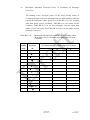
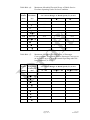
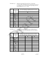
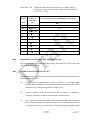


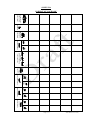
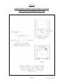
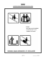
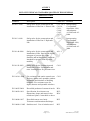
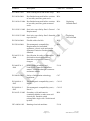
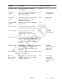
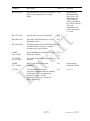


![Lifts Part 4: Operational Management [PDF 707Kb]](http://vs1.manualzilla.com/store/data/006003154_1-8f988a4c31a2e96372488ae8439271db-150x150.png)