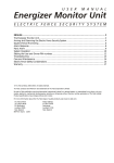
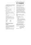
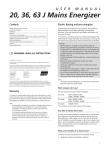
1
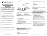
®
Instruction Manual
innovation
12 V
technology
TM
Read all instructions
Save these instructions
performance
power
Contents
Electric fencing and your Stafix energiser.................... 1
Installation ................................................................ 1
Operation.................................................................. 2
Battery selection and management ............................ 4
© Tru-Test Limited, 2004. All rights reserved.
Stafix is a trademark of Tru-Test Corporation Limited.
Temporary electric fencing ......................................... 6
No part of this publication may be photocopied, reproduced, stored in a
retrieval system, or transmitted in any form or by any means, electronic,
mechanical, photocopying, recording or otherwise without the prior written
permission of Tru-Test Limited. Product specifications may change without prior
notice.
Safety considerations ................................................. 6
For more information about the Stafix range of quality products, see
www.stafix.com.
Frequently asked questions/Troubleshooting .............. 8
Tru-Test Limited
25 Carbine Road
Mt Wellington
Auckland 1006
New Zealand
Building a permanent electric fence ........................... 4
Servicing.................................................................... 8
Product specifications ................................................ 8
803157 Issue 1 6/04
Postal address:
P O Box 51078
Pakuranga
Auckland 1730
New Zealand
Electric fencing and your Stafix
energiser
Warning!
- Do not connect to mains-operated or line-operated
equipment.
- Remove the battery from the energiser before using an
external battery charger to recharge the battery.
- Switch the energiser off before installation or performing
any work on the fence.
Congratulations on your purchase of a Stafix battery energiser.
This product has been constructed using the latest technology
and construction techniques. It has been engineered to give
superior performance and many years of service.
It is important to carefully and thoroughly read these
instructions. They contain important safety information and
will assist you in ensuring that your electric fencing system
gives maximum performance and reliability.
Note: This product has been designed for use with electric
animal fences.
Explanation of symbols that may be on your energiser
Installation
To reduce the risk of electric shock, the energiser
should only be opened and/or repaired by qualified
Stafix appointed personnel.
To set up the energiser for use, install the battery and connect
the energiser to an electric fence and an earthing system.
Read full instructions before use.
Installing the battery
This battery energiser is intended for connection to a
12 V battery.
This battery energiser must not be connected to a
battery while the battery is being charged by a
mains/line operated charger. Do not connect the
energiser or the battery wiring to any other mains /line
operated equipment.
1
2
3
4
How does an electric fence work?
An electric fence system comprises an energiser and an
insulated fence. The energiser puts very short pulses of
electricity onto the fence line. These pulses have a high
voltage, but are of very short duration (less than 3/10,000ths
of a second). However, a shock from an electric fence pulse is
very uncomfortable and animals quickly learn to respect
electric fences. An electric fence is not only a physical barrier,
but is also a strong psychological barrier.
5
Place the energiser on a flat surface. Open the lid of the
energiser by releasing the side latches. Remove any loose
accessories from the battery compartment.
Select a 12 V battery to use with the energiser.
Place the battery in the battery compartment.
Connect the red, positive (+ve) energiser clip to the
positive terminal on the battery and the black, negative
(-ve) energiser clip to the negative terminal on the
battery.
Close the lid of the energiser.
Positioning
Position the energiser on firm ground away from flooding and
out of reach of animals and children. If possible, position the
energiser in a sheltered area to protect it from the weather.
Connecting to an electric fence
What are the benefits of an electric fence?
An electric fence has many benefits over conventional fencing:
•
•
•
•
Requires less labour and material to construct than
conventional fencing.
Flexibility to change or add paddocks when required. The
use of strip grazing techniques can allow temporary
fencing to be quickly and easily erected or removed.
Controls a broader range of animals.
Minimises damage to expensive livestock when compared
with other fencing mechanisms, for example barbed wire.
1
2
3
Push earth rods fully into firm ground. See Installing and
testing an earth system on page 6.
Connect the green lead from the energiser’s Fence earth
terminal
(green) to the earthing system.
Connect the red lead from the energiser’s Fence
output terminal (red) to the fence. Make sure there is a
good contact. If necessary, carefully strip the polywire to
expose steel strands in order to provide a good
connection.
1
Joint clamp
Fence
output
terminal
Fence
earth
terminal
Half
power
The energiser is operating at
approximately half the output
power of the Full Power setting.
Off
The energiser is off and is not
operating.
Pulse speed switch
Earth
system
This switch controls the output pulse speed and behaviour of
the energiser. There are four settings:
Solar installation
Setting
Description
Fast
The energiser will pulse fast at all
times.
Auto
The energiser will adjust its pulse
speed to conserve battery power,
depending on the battery charge
level. See the table below.
Fast nocturnal
The energiser will pulse fast at
night and slow speed during the
day (used where stock or predators
are nocturnal). However, if the
battery charge level is Low, the
pulse speed during the day will
change to being very slow.
Slow nocturnal
The energiser will pulse at slow
speed at night and fast speed
during the day. However, if the
battery charge level is Low, the
pulse speed during the night will
change to being very slow.
Solar panel selection, assembly and positioning
Refer to the Stafix website www.stafix.com for information
about selecting components, assembling and positioning a
solar energiser system.
Operation
- Keep this manual in a handy location.
- Carefully read all the safety information in this manual. See
Safety Considerations on page 6.
- Carefully check your installation to ensure that it complies
with all local safety regulations.
•
Select the output setting using the Power Output switch
(see Power Output switch on page 2). One of the three
output performance indicator lights will flash with each
pulse. The lights indicate the approximate voltage at the
Fence output terminals, except when the Power Output
switch is set to Full Power with Battery Test.
Note: In all switch positions, the energiser will stop
functioning before the battery discharges completely. This
helps to prevent battery damage.
Auto setting
Recommended.
Indicates a load on the energiser.
Attention required to ensure reliable
animal control.
Fence is heavily loaded and needs
urgent attention.
If at any time all the indicator lights flash for more than
10 seconds, turn off the energiser for approximately
10 seconds, then turn it on again.
•
If the indicator lights continue to flash, return the
energiser to the nearest authorised service agent.
The energiser functions according to the position of the Power
Output and Pulse Speed switches. See the diagram of the
energiser on page 1.
•
Power output switch
This switch controls the power output setting of the energiser.
2
Setting
Description
Full power
The energiser is operating at full
output power.
Full power
with
battery
test
The energiser is operating at full
output power, but indicator lights
show the battery level. See Battery
test setting on page 2 for an
explanation of the indicator lights.
When the Pulse Speed switch is set to Auto, the pulse speed
varies according to the battery charge level.
Battery charge level
Pulse speed
Optimal
Fast – approximately 1½ seconds
between pulses
Medium
Slow – approximately 2½
seconds between pulses
Low
Very slow – approximately 3½
seconds between pulses
Battery test setting
When the Power Output switch is set to Full Power with Battery Test, the indicator lights show the charge level of the battery and
other battery information. The battery test is only relevant when a lead-acid battery is used. The table below explains what the
indicator lights represent and any action required for each installation.
Lights
Battery-only installation
Solar installation
Green light on
Optimal battery charge level:
•
No action required.
Optimal battery charge level. (Readings for a solar installation
are only accurate in the early morning or late evening when
the solar panel has been out of the sunlight for several
hours.)
Yellow light on
Medium battery charge level:
•
Monitor battery charge level.
•
Recharge the battery to avoid long
term battery damage.
Low to Medium battery charge level:
•
Recharge the battery immediately.
•
Check the solar panel wiring is connected properly and
is intact.
•
Check that the solar panel is installed correctly and is
clean.
If the problem recurs, the panel may be inadequate or faulty.
•
Take the entire system to an authorised service agent for
assessment.
Red light on
Low battery charge level:
•
Recharge the battery immediately.
Low battery charge level:
•
See Low to Medium battery charge level above
Green light
flashing
Not applicable.
Battery connections may be faulty:
•
Check that the battery clips are connected properly and
that the wiring is intact.
Battery may be over-charged or faulty:
•
Disconnect the solar panel for 24 hours
•
Reconnect the solar panel and monitor for seven days.
If the light flashes within seven days, there may be
something wrong with the system.
•
Take the entire system to an authorised service agent for
assessment.
Red light
flashing
Battery may be faulty:
•
Recharge the battery and monitor
battery performance for seven days.
•
If the light flashes within seven days,
the battery should be checked by a
battery specialist and replaced if
necessary.
Battery may be faulty:
•
Recharge the battery and monitor battery performance
for seven days.
•
If the light flashes within seven days, the battery should
be checked by a battery specialist and replaced if
necessary.
3
Battery selection and management
This section refers exclusively to rechargeable, wet-cell leadacid batteries, for example car, tractor, truck, marine or
specialist deep-cycle batteries.
A battery-only installation has unique requirements. Regular
recharging of the battery is essential. Use a suitably-rated
battery charger to recharge the battery. Refer to the battery
manufacturer’s recommendations.
1
The battery you select will depend on whether your
installation is a battery-only or a solar installation.
2
Battery selection for a battery-only installation
The battery selected should have the highest amp hour (Ah)
rating possible while still fitting inside the battery
compartment. The dimensions of the battery compartment
are 210x240x290 mm (8¼x9½x11½”) (WxHxD).
3
4
For best system reliability and long term battery life, the
preferred battery and charging regime is use a deep-cycle,
lead-acid battery and to recharge it when it has discharged
to Medium charge level.
The table below shows the number of days the energiser can
operate before the battery requires recharging. The table is
based on the energiser operating with an 80 Ah battery
discharged to 20%. Although operating time can exceed the
number of days shown here, this is likely to cause battery
damage and will necessitate frequent replacement of the
battery.
Energiser
model
Selector switch
positions
Current
required
Operating
time (days)
CB1.2
Full Power-Fast Pulse
Full Power-Slow Pulse
125 mA
70 mA
21
38
CB2.3
Full Power-Fast Pulse
Full Power-Slow Pulse
240 mA
125 mA
11
21
As a guide, the minimum amp hour (Ah) rating of the 12 V
lead-acid battery required for each model is shown below.
This table is based on average usage over seven days with no
sunlight. For more detailed information, refer to the Stafix
website www.stafix.com.
Selector switch positions
Current
required
Minimum
battery
capacity
CB1.2
Full Power-Fast Pulse
Full Power-Slow Pulse
125 mA
70 mA
26 Ah
15 Ah
CB2.3
Full Power-Fast Pulse
Full Power-Slow Pulse
240 mA
125 mA
50 Ah
26 Ah
Battery management
Battery charging
Warning! The battery energiser is not rated for
connection to mains-operated or line-operated
equipment. Ensure that the battery is disconnected from
the energiser before connecting the battery to any mainsoperated or line-operated battery charging device. Failure
to observe this precaution could result in damage to the
energiser and possible electrocution.
4
A correctly installed solar energiser system requires very little
battery maintenance. The solar panel selected should be
sufficient to maintain the battery at full or near-full charge.
Warning! Batteries contain harmful chemicals and when
used incorrectly, may cause injury. Observe the guidelines
for battery care, maintenance and safety in this manual
and in the documentation supplied with your battery.
Battery care and maintenance
•
•
The battery and solar panel must be selected carefully to suit
the energiser's electrical current consumption. This will
depend on the position of the energiser selector switch, the
energiser model being used and the amount of sunshine at
the location of the installation.
Energiser
model
Caution! Over-charging the battery will reduce its life.
Do not exceed the recommendations of the battery
manufacturer on recharging the battery from a mains- or
line-powered source.
•
Battery selection for a solar installation
Disconnect the battery from the energiser.
Attach the positive (+) battery charger lead to the
positive terminal of the battery, and the negative (–)
battery charger lead to the negative terminal on the
battery.
Insert the battery charger’s input power plug into a
mains or line socket and turn on the power supply.
After the battery is charged, disconnect it from the
battery charger before connecting it to the energiser.
•
•
When not in use, keep the battery as fully charged as
possible.
Recharge a discharged battery as soon as possible.
Batteries should be stored fully charged and recharged
at regular intervals (every 8 weeks)
Inspect the battery regularly to ensure that the
electrolyte level does not fall below 12 mm (½”) above
the surface of the battery plates.
Fill using deionised, distilled or rain water. Do not
overfill. Refer to the battery manufacturer’s
recommendations for more information.
Battery safety
•
•
•
Ensure that the battery is well ventilated when
recharging.
Avoid temperatures greater than 50 °C (120 °F).
Ensure the battery is not exposed to naked flame or
sparks.
Building a permanent electric fence
Components of an electric fence
An electric fence system comprises the following elements:
•
•
•
•
An energiser.
An earth system. This comprises a number of metal
rods inserted into the ground, which are connected to
the Fence earth terminal on the energiser.
Stafix insulated underground cables. Used to connect
the energiser to the earth and fence.
An insulated fence. Connected to the Fence output
terminal of the energiser. Fences can be made to a
variety of designs (see below).
Note: The animal receives a shock when it completes a
circuit between the fence and the earth system. The fence
below has all live wires and requires conductive soils. These
fences are often referred to as ‘all-live’ or ‘earth-return’
fences.
Sheep, goats, cattle and horses
10 m (33’) spacing, posts only
15 m (49’) spacing with droppers
Other useful components that can be added:
Cut-out switches. Installed at regular
intervals, these allow you to isolate sections
of the fence for repair.
Lightning diverter kit. Used to minimise the
damage to your energiser from lightning
conducted down the fence line.
Wild animals
Alternative installation
7 wire, 10 m (33’) spacing with droppers
For poor conductivity soils (dry or sandy), a ‘fence-return’ or
‘earth-wire-return’ system is recommended. On these fences
the Fence earth terminal is connected directly to at least one
of the fence wires. The animal gets maximum shock from
touching a live and earth wire at the same time.
End assemblies
Angle stay
Fence designs
Fences can be constructed to suit the type of livestock and
materials available. Discuss with your Stafix distributor which
design best suits your needs. Some suggested fence
configurations are below.
Suitable for field gate, high-tension strainer.
After firmly setting the footed strainer in the ground, dig in
the stay block just below ground level, at a distance to
ensure the angle stay will be held snugly in position. The stay
can be levered into position with a spade.
All-live system
Cattle and horses
10-15 m (33-49’) spacing, posts only
15-20 m (49-65’) spacing with droppers
Earth-return system
5
Horizontal stay
Suitable for field gate, high-tension strainer.
Very simple to erect and most suitable as a high tension
strainer, excellent in areas where the soil gets very wet or
where heavy frost occurs.
Temporary electric fencing
Stafix offers a range of products that allow the farmer to
construct a temporary electric fence. A temporary fence that
can be quickly erected and easily moved allows the farmer to:
•
•
•
Installing and testing an earth system
Select a suitable site for the earth system. Sites need to be:
At least 10 m (33’) from other earth systems (e.g.
telephone, mains power or the earth system from
another energiser).
•
Away from stock or other traffic that could interfere
with the installation.
•
At a site that can be easily observed for maintenance.
•
Ideally at a site that has damp soil (e.g. a shaded or
swampy location). Note that the earth does not need to
be directly adjacent to the energiser installation.
Drive Stafix earth rods into the ground. Use high-voltage,
insulated cable and earth clamps to continuously connect the
earth rods and the energiser’s Fence earth terminal. Make
sure the insulation is stripped back to ensure good contact
between the wire and the earth rod. The table below
specifies the minimum number of 2 m (6’6”) earth rods
recommended for an earthing system:
Make smaller paddocks (fields)
Keep herds of animals separated
Ration feed
Note: Use more wires for smaller animals and wild animals.
Politape should be used when greater visibility is required
(e.g. horses).
An example of a temporary fence is shown below.
•
Energiser
Earth rods
CB1.2: 1.2 J
2
CB2.3: 2.3 J
3
Test the earth system, using the following procedure:
1
2
3
4
5
Turn off the energiser.
At least 100 m (330’) away from the energiser, short
circuit the fence by laying several steel rods or lengths of
pipe against the fence. For best results, the fence
voltage should be lowered to 2000 V or less. In dry or
sandy conditions, it may be necessary to drive the rods
up to 300 mm (12”) into the earth.
Note: It is not acceptable to short-circuit a fence return
system to the earth wire of the fence.
Turn the energiser back on.
Using a Stafix Digital Voltmeter, ensure that the fence
voltage is below 2 kV.
Check your earth system. Insert the voltmeter’s earth
probe into the ground at the full extent of the lead, and
hold the hook against the last earth rod. The tester
should not read more than 0.3 kV. Anything higher than
this indicates that better earthing is required. Either add
more earth rods or find a better ground area to drive in
the earth rods.
Note: When earthing energisers located in dairies, earth at
least 20 m (65’) away from the dairy using double-insulated
wire to avoid touching the dairy building or equipment.
Safety considerations
Definition of special terms
Electric fence energiser – An appliance that is intended to
periodically deliver voltage impulses to a fence connected to
it.
Fence – A barrier for animals or for the purpose of security,
comprising one or more conductors such as metal wires,
rods or rails.
Electric fence – A barrier which includes one or more electric
conductors, insulated from earth, to which electric pulses are
applied by an energiser.
Fence circuit – All conductive parts or components within an
energiser that are connected or are intended to be
connected, galvanically, to the output terminals.
Earth electrode – Metal structure that is driven into the
ground near an energiser and connected electrically to the
Fence earth terminal of the energiser, and that is
independent of other earthing arrangements.
Connecting lead – An electric conductor, used to connect
the energiser to the electric fence or the earth electrode.
Electric animal fence – An electric fence used to contain
animals within or exclude animals from a particular area.
Electric security fence – A fence used for security purposes
which comprises an electric fence and a physical barrier
electrically isolated from the electric fence.
Physical barrier – A barrier not less than 1.5 m (5’) high
intended to prevent inadvertent contact with the pulsed
conductors of the electric fence. Physical barriers are typically
constructed from vertical sheeting, rigid vertical bars, rigid
mesh, rods or chainwire mesh.
Public access area – Any area where persons are protected
from inadvertent contact with pulsed conductors by a
physical barrier.
6
Pulsed conductors – Conductors which are subjected to
high voltage pulses by the energiser.
Secure area – The side of an electric security fence where a
person may come into contact with the electric fence,
without the protection of a physical barrier.
If connecting leads and electric animal fence wires are
installed near an overhead power line, the clearances shall
not be less than those shown in the table below.
Minimum clearances from power lines for electric animal
fences
Requirements for electric animal fences
Electric animal fences and their ancillary equipment shall be
installed, operated and maintained in a manner that
minimises danger to persons, animals or their surroundings.
This energiser is not intended for use by young children or
infirm persons unless they have been adequately supervised
by a responsible person to ensure that they can use the
energiser safely.
Young children should be supervised to ensure that they do
not play with the energiser.
Electric animal fence constructions that are likely to lead to
the entanglement of animals or persons shall be avoided.
An electric animal fence shall not be supplied from two
separate energisers or from independent fence circuits of the
same energiser.
For any two separate electric animal fences, each supplied
from a separate energiser independently timed, the distance
between the wires of the two electric animal fences shall be
at least 2 m (6’6”). If this gap is to be closed, this shall be
effected by means of electrically non-conductive material or
an isolated metal barrier.
Barbed wire or razor wire shall not be electrified by an
energiser.
A non-electrified fence incorporating barbed wire or razor
wire may be used to support one or more offset electrified
wires of an electric animal fence. The supporting devices for
the electrified wires shall be constructed so as to ensure that
these wires are positioned at a minimum distance of
150 mm (6”) from the vertical plane of the non-electrified
wires. The barbed wire and razor wire shall be earthed at
regular intervals.
>1000 ≤33,000 V
4 m (13’)
>33,000 V
8 m (27’)
In electric animal fences intended for deterring birds from
roosting on buildings, no electric fence wire shall be
connected to the energiser earth electrode. A warning sign
shall be fitted to every point where persons may gain ready
access to the conductors.
Where an electric animal fence crosses a public pathway, a
non-electrified gate shall be incorporated in the electric
animal fence at that point or a crossing by means of stiles
shall be provided. At any such crossing, the adjacent
electrified wires shall carry warning signs.
Any part of an electric animal fence that is installed along a
public road or pathway shall be identified at frequent
intervals by warning signs securely fastened to the fence
posts or firmly clamped to the fence wires.
•
Connecting leads and electric animal fence wires shall not
cross above overhead power or communication lines.
3 m (10’)
2 m (6’6”) for power lines operating at a nominal
voltage not exceeding 1000 V.
•
15 m (50’) for power lines operating at a nominal
voltage exceeding 1000 V.
Electric animal fences intended for deterring birds, household
pet containment or training animals such as cows need only
be supplied from low output energisers to obtain satisfactory
and safe performance.
A distance of at least 10 m (33’) shall be maintained
between the energiser earth electrode and any other
earthing system connected parts such as the power supply
system protective earth or the telecommunication system
earth.
Connecting leads shall not be installed in the same conduit
as the mains supply wiring, communication cables or data
cables.
≤1000 V
•
•
Connecting leads that are run underground shall be run in
conduit of insulating material or else insulated high voltage
cable shall be used. Care must be taken to avoid damage to
the connecting leads due to the effects of animal hooves or
vehicle wheels sinking into the ground.
Clearance
If connecting leads and electric animal fence wires are
installed near an overhead power line, their height above the
ground shall not exceed 3 m (10’). This height applies to
either side of the orthogonal projection of the outermost
conductors of the power line on the ground surface, for a
distance of:
Follow our recommendations regarding earthing. See
Installing and testing an earth system on page 6.
Connecting leads that are run inside buildings shall be
effectively insulated from the earthed structural parts of the
building. This may be achieved by using insulated high
voltage cable.
Power line voltage
The size of the warning sign shall be at least
100x200 mm (4x8”).
The background colour of both sides of the warning
sign shall be yellow. The inscription on the sign shall be
black and shall be either:
or the substance of “CAUTION: Electric animal fence”.
•
The inscription shall be indelible, inscribed on both sides
of the warning sign and have a height of at least
25 mm (1”).
Ensure that all mains-operated, ancillary equipment
connected to the electric animal fence circuit provides a
degree of isolation between the fence circuit and the supply
mains equivalent to that provided by the energiser.
Protection from the weather shall be provided for the
ancillary equipment unless this equipment is certified by the
manufacturer as being suitable for use outdoors, and is of a
type with a minimum degree of protection IPX4.
Crossings with overhead power lines shall be avoided
wherever possible. If such a crossing cannot be avoided it
shall be made underneath the power line and as nearly as
possible at right angles to it.
7
Frequently asked
questions/Troubleshooting
If the fence, earth and energiser are in good condition and
the voltage is still below 4 kV, talk to your Stafix distributor.
They will help you identify whether recent extensions to your
fence, a poor fence layout, or soil conditions may be causing
inadequate voltage.
What voltage is required to control animals?
4 kV is widely accepted as the recommended minimum
voltage to control animals. However, you also require a well
constructed fence system to ensure that animals cannot push
through electrified wires.
The fence voltage is below 4 kV. How do I increase the
voltage?
Check the energiser. Ensure that the energiser is not set to
operate at half power. Disconnect the energiser from the
fence and earth system. Measure the voltage across the
energiser terminals with a Stafix Fence Compass, DVM or Lite
Tester. If the voltage is less than 6 kV, request your Stafix
service agent to check the energiser.
How do I locate faults?
The recommended tool for locating faults is the Stafix Fence
Compass. This combined voltage and current meter allows
you to rapidly locate sources of current leakage. Alternatively,
use a Stafix DVM or Lite Tester. Use cut-out switches to turn
off the power to different sections of the farm. If the voltage
on the fence increases when a section of the farm is turned
off, then investigate that section for possible faults.
There are no lights flashing on the energiser.
Check the power supply. Ensure that the power is switched
on. If the energiser still does not operate, request your Stafix
service agent to check the energiser.
Check the energiser earthing. Use the procedure described
in Installing and testing an earth system on page 6.
Check your fence system for faults. The most common
source of low voltage is faults on the fence line.
Servicing
This energiser contains no user serviceable parts. It must be
returned to a Stafix-appointed service agent for repair.
Product specifications
8
CB1.2
CB2.3
Power supply (12.6 V nominal)
11–15 V dc
11–15 V dc
Current consumption
Full power-fast pulse
Half power-fast pulse
125 mA
70 mA
240 mA
125 mA
Output voltage
No load
500 Ω
10. 5 kV
5.3 kV
10.7 kV
5.9 kV
Maximum output energy
1.28 J at 600 Ω
2.5 J at 400 Ω
Stored energy
1.65 J
3.3 J
Dimensions (WxHxD)
342x400x253 mm
(13½x15¾x10”)
342x400x253 mm
(13½x15¾x10”)
Weight
3.14kg (6 lb, 15 oz)
3.14 kg (6 lb, 15 oz)
®
www.stafix.com
TM
Read all instructions
Save these instructions