1
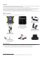
USER MANUAL XRP2 Panel Reader and Antenna Contents Overview ............................................................................................... 2 © 2013-2015 Tru-Test Limited What’s in the box? ................................................................................ 2 All product names and brand names in this document are trademarks or registered trademarks of their respective holders. Optional accessories.........................................................................................2 Components of the Tru-Test XRP2 EID Panel Reader System ................... 3 Parts of the panel reader ..................................................................................3 Panel reader LCD .............................................................................................3 Panel reader power supply ...............................................................................3 Antenna ..........................................................................................................3 Ways to use the panel reader ................................................................ 4 Installing the panel reader and antenna ................................................. 4 Example installation .........................................................................................4 Installation information ....................................................................................4 Alternative installation options .........................................................................5 Connecting to an indicator (optional) ..................................................... 7 Connecting to a Bluetooth® enabled indicator ..................................................7 Connecting to an indicator that does not offer Bluetooth® wireless connectivity......................................................................................................7 No part of this publication may be photocopied, reproduced, stored in a retrieval system, or transmitted in any form or by any means, electronic, mechanical, photocopying, recording or otherwise without the prior written permission of Tru-Test Limited. Product specifications may change without prior notice. For more information on other quality Tru-Test Group brands and products, visit www.tru-test.com. Tru-Test Limited 25 Carbine Road Mt Wellington Auckland 1060 New Zealand Postal address: P O Box 51078 Pakuranga Auckland 2140 New Zealand The Bluetooth® word mark and logos are registered trademarks owned by Bluetooth SIG, Inc. Any use by Tru-Test Limited is under licence. All trademarks with an * are not owned by Tru-Test Limited and belong to their respective owners. Issue 4 05/2015 Recording EID tags ................................................................................ 7 Recording EID tags when the panel reader is connected to another device ........7 Recording EID tags when the panel reader is being used on its own (standalone).....................................................................................................7 Transferring information from the panel reader ...................................... 8 Transferring sessions from the panel reader to a PC using Data Link .................8 Transferring sessions from the panel reader using an Android* smartphone ......8 Modifying the panel reader settings ....................................................... 9 Modifying the panel reader settings using the menu options on the panel reader itself......................................................................................................9 Modifying the panel reader settings using Data Link .......................................10 Troubleshooting .................................................................................. 13 Caring for the panel reader and antenna.............................................. 15 Service and warranty information......................................................... 15 Upgrading the software ....................................................................... 15 Specifications ...................................................................................... 16 Panel Reader .................................................................................................16 Antennas .......................................................................................................16 Compliance ......................................................................................... 17 FCC notice .....................................................................................................17 FCC warning ..................................................................................................17 Industry Canada notice ..................................................................................17 Industry Canada warning ...............................................................................17 EC Declaration of Conformity .........................................................................17 Conformité .......................................................................................... 17 Avis d'Industrie Canada .................................................................................17 Avertissement d'Industrie Canada ..................................................................17 Déclaration CE de conformité .........................................................................17 1 Overview This user manual contains installation and user instructions for the Tru-Test XRP2 EID1 Panel Reader System which identifies and reads electronic tags on individual animals, allowing for accurate traceability and management of stock. The Tru-Test XRP2 EID Panel Reader System consists of an XRP2 EID Panel Reader with a Large or Small antenna. The Tru-Test XRP2 EID Panel Reader (the panel reader) is a dual mode FDX-B / HDX EID reader optimized for high performance with ISO animal tags, operating at 134.2 KHz with read distances of up to 1 m, depending on the tag and environmental conditions. It includes a fast auto-tuning technique and Digital Signal Processing capability to increase read range and to reduce unwanted interference effects. A Tru-Test Large or Small antenna is connected to the panel reader; the panel reader may be connected to a Tru-Test weigh scale indicator or to a PC. What’s in the box? Check that you have all of the following items. If anything is missing, contact your supplier. Panel Reader-Serial cable Connects the panel reader to a weigh scale indicator (an indicator) XRP2 panel reader (the panel reader) Large or Small antenna (may be supplied separately) The 5 m extension lead supplied may be used to connect the antenna to the reader (optional). Serial-USB adaptor cable Together with Panel Reader-Serial cable, provides connection to a PC Mains power adaptor (differs depending on region) USB flash drive/CD Contains Data Link software and reference information Battery leads Mounting bracket Optional accessories These optional accessories may be ordered separately from your local Tru-Test representative. They are not required for a typical setup. 1 2 Dual antenna adaptor – used to connect two antennas to a single panel reader. See Using two antennas on page 5. Synchronisation cable - used to connect two panel readers together. See Synchronising two panel readers on page 5. EID = Electronic Identification. This term is equivalent to RFID = Radio Frequency Identification, in respect of this and similar products. Components of the Tru-Test XRP2 EID Panel Reader System Parts of the panel reader Panel reader LCD Panel reader power supply The panel reader can be powered by a 12 V battery, using the battery leads supplied. The panel reader operates well from a 12 V automotive battery, however a marine battery is less prone to permanent damage if the battery is not charged at least every few days. Connect the red clip to the positive terminal (+) on the battery and the black clip to the negative terminal (-). Alternatively, the panel reader may be powered by mains power using the mains power adaptor supplied. Notes: - The panel reader does not have an on/off switch. It switches on automatically when a power source is applied. The Power LED (red) illuminates to show that the panel reader is on. - If the Power LED (red) is flashing, this indicates that the battery voltage is too low. Disconnect the battery and recharge it. Antenna An antenna allows the panel reader to read EID tags. The antenna creates a magnetic field to energize the EID tag and it receives the very small signals transmitted by the tag. Only a Tru-Test antenna should be used with the panel reader. There are two types of antenna available, a Large and a Small antenna. The panel reader continually monitors the state of the antenna. Warning messages displayed on the LCD indicate when a fault exists. A diagnostics menu in the panel reader settings provides additional information. See Panel reader settings on page 9. 3 Ways to use the panel reader The panel reader can be used in two ways: 1 2 Standalone - the panel reader saves each scanned tag in its internal memory. These records can be transferred afterwards. See Transferring information from the panel reader on page 8. Connected – the panel reader immediately transmits every scanned tag to a connected device, such as an indicator. Installing the panel reader and antenna Example installation In the example below, a single panel reader is being used as part of a weighing system. The panel reader and antenna are mounted to a cattle crush and the panel reader is connected to an indicator and load bars. When the animal enters the cattle crush, its EID tag number is scanned by the panel reader and sent to the indicator. XRP2 Panel Reader Tru-Test Antenna Tru-Test Indicator EID Tag Installation information The panel reader and antenna can be mounted onto a flat surface (timber rails, concrete), or onto metal pipe-work, using the hardware supplied. If you have a Large antenna, the panel reader can also be mounted directly on the back of the antenna. Factors to consider: The panel reader and antenna should be installed on the outside of a crush/chute, weigh crate or drafter so that it is not damaged by animal movement. Animal flow must be restricted to ensure that only one animal is within the antenna’s read range. The location of the antenna in relation to metal bars or pipes needs to be considered. See Troubleshooting on page 13. The positioning of the antenna is important to obtain an effective read of the EID tag: Front of crush/chute, weigh crate or drafter Read zone Keep animals out of this area. Animals inside this area could adversely affect read performance and may damage the antenna Antenna Animal flow inside crush/chute, weigh crate or drafter Antenna After you have installed the antenna and reader, connect the antenna to the panel reader. An extension lead may be required (supplied with the antenna). 4 Alternative installation options Using two antennas If an increased operating area is required, two antennas may be connected to a single panel reader using a Dual Antenna Adaptor. A dual antenna adaptor can be ordered by contacting your local Tru-Test representative. Note: A dual antenna adaptor must not be used with only one antenna. A single antenna may read a tag as far as 1 m away, dependant on the installation: Antenna Panel Reader Tag travel Tag ~1 m Using a second antenna with a Dual Antenna Adaptor will almost double the read area. Antenna 1 Panel Reader Antenna 2 Tag travel Tag Dual Antenna Adaptor ~1.8 m Depending on tag orientation, it is best to experiment to determine the optimum distance between the two antennas. The distance will range from the maximum read range of one antenna (~1 m in the above example) to almost double that (~ 1.8 m in the above example). The two antennas may be set up so that they are aiding (facing the same way), or opposing (facing towards each other), as pictured here. For more information, contact your local Tru-Test representative. Synchronising two panel readers If two panel readers are installed in close proximity of each other (within 50 m [150 ft]), they must be synchronised, or performance will be reduced. To synchronise two panel readers, a Synchronisation Cable must be used. This is an optional accessory which can be ordered by contacting your local Tru-Test representative. The synchronisation cable connects the two panel readers via the Power connectors. Each panel reader must be connected to its own indicator. Full instructions on how to synchronise two panel readers will be supplied when the cable is ordered. 5 Antenna cable Panel Reader 1 Tru-Test weigh scale indicator Antenna cable Antenna 2 Antenna 1 Panel Reader 2 Tru-Test weigh scale indicator Synchronisation cable If two readers are synchronised, it is possible to set up ‘dynamic field operation’ for even greater tag read probability. For more information, contact your local Tru-Test representative. 6 Connecting to an indicator (optional) Connecting to a Bluetooth® enabled indicator To establish a Bluetooth wireless connection between the panel reader and a Tru-Test Bluetooth enabled indicator, you need to ‘pair’ the two devices. The panel reader can be paired with any Tru-Test Bluetooth enabled indicator and to some third party devices. ® Note: When connecting the panel reader wirelessly to a Tru-Test indicator, always turn the indicator on BEFORE the panel reader. 1 2 3 4 With both devices off, position the panel reader within 5 metres of the indicator. Switch on the indicator and, if necessary, check that its Bluetooth setting is enabled. Connect the panel reader to a power source (battery or mains power). Wait for up to 1 minute until the two devices are paired. When pairing is complete, the panel reader’s Bluetooth wireless connection LED (blue) illuminates and the LCD displays the name of the connected device. Use the panel reader to scan an EID tag in order to test the connection. ® Connecting to an indicator that does not offer Bluetooth® wireless connectivity Connect the panel reader to the indicator using the Panel Reader-Serial cable supplied. Follow the instructions provided with your indicator. Recording EID tags The method used to record EID tags differs depending on whether the panel reader is being used ‘standalone’ or ‘connected’ (to another device such as an indicator). For more information, see Ways to use the panel reader on page 4. Recording EID tags when the panel reader is connected to another device Refer to example installation diagram in Installing the panel reader and antenna on page 4. 1 2 Set up the indicator or other device for a recording session, according to the instructions provided with the device. Move the animal into the cattle crush. When the animal passes near the antenna, the EID tag will be read by the panel reader and then sent to the connected indicator. The EID tag is recorded into the indicator’s internal memory. The EID tag number will appear on the panel reader’s LCD, the Read LED (green) will flash and the panel reader will beep to indicate that the tag has been read successfully. Recording EID tags when the panel reader is being used on its own (standalone) 1 2 Start a new recording session by pressing. . The panel reader beeps and the session number appears on the LCD. Move the animal into the cattle crush. When the animal passes near the antenna, the EID tag will be read by the panel reader and recorded into its internal memory. The EID tag number will appear on the panel reader’s LCD, the Read LED (green) will flash and the panel reader will beep to indicate that the tag has been read successfully. 7 Transferring information from the panel reader Information can be transferred to and from the panel reader by connecting it to a Windows* PC or an Android* smartphone. Transferring sessions from the panel reader to a PC using Data Link Note: Do NOT connect the panel reader to the PC until you have installed the Data Link software, supplied on USB flash drive/CD. In order to transfer information from the panel reader to a PC, you must first install Data Link on the PC. To do this, insert the USB flash drive into a USB port or insert the CD into the CD drive on your PC and follow the instructions. 1 Connect the panel reader to a PC using the Panel Reader-Serial cable and the Serial-USB adaptor cable supplied. 2 3 Launch the Data Link application. Wait for the panel reader to connect to the PC (this may take up to a minute). Transferring sessions from the panel reader using an Android* smartphone In order to use a smartphone to transfer sessions, you must first install Tru-Test Data Link on your smartphone. This free app can be downloaded from the Google Play* Store. The panel reader’s Bluetooth® wireless connectivity setting must be set to Manual in order to connect to a smartphone. See Modifying the panel reader settings on page 9. Instructions for using the Tru-Test Data Link app are available on the Tru-Test website www.tru-test.com. 8 Modifying the panel reader settings You can modify the panel reader settings using the menu options on the panel reader itself, or by connecting the panel reader to a PC and using Data Link. Modifying the panel reader settings using the menu options on the panel reader itself To access the panel reader settings: Press . The first three items appear on the LCD. To scroll through and highlight options, press or To select a highlighted option or modify a setting, press repeatedly. . To exit out of the panel reader settings, highlight EXIT, then press . Panel reader settings Menu name Options Description BLUETOOTH® Auto* The panel reader will automatically connect to previously used devices or other Tru-Test devices. Manual This setting should be used when connecting to a panel reader from an Android™ smartphone or other Bluetooth enabled device. Off Disables the Bluetooth wireless connection. Allows you to manually search for other Bluetooth enabled devices. FIND BT DEVICES PAIRED DEVICES DUPLICATES OUTPUT MODE DATA FORMAT DIAGNOSTICS Lists previously paired devices. Select from this list to connect to another device. On* The panel reader will not record the same EID twice in the same session. Off The panel reader will record the same EID twice in the same session. Single* The panel reader will only record and send the same EID once. Cont (Continuous) The panel reader will record only once but send the same EID each time it is read. Data format changes the way that EIDs are stored and output from the panel reader. Dec 1 (Decimal 1)* Standard decimal format with a space between the country (or a manufacturer's, possibly shared) code and the national identification (or a manufacturer's unique within series) code e.g. 826 123456789012. Dec 2 (Decimal 2) Decimal format used in some countries with no space between the country (or a manufacturer's, possibly shared) code and the national identification (or a manufacturer's unique within series) code e.g. 826123456789012. Hex (Hexadecimal) e.g. 8000F58000000001. ISO Complies with ISO 24631-6 e.g. 1000000826000000123456. There are four diagnostics screens which provide troubleshooting information. Select NEXT to scroll through the screens. If the values fall outside the normal range, see Troubleshooting on page 13. Supply voltage The power supply voltage is displayed and should be followed by (OK). Antenna voltage and tuning value The antenna voltage is displayed and should be followed by (OK). The tuning value is displayed. The graph should show a dot in the middle band and be followed by (OK). Noise level Displays the levels of interference being detected. The noise level should be in the lower part of the graph. Read rate Displays the reads per minute for the current location of the tag. SOFTWARE VERSION LANGUAGE The panel reader software version. ENGLISH ESPAÑOL PORTUGUÊS FRANÇAIS DEUTSCH You can change the language displayed on the panel reader’s LCD. 9 Modifying the panel reader settings using Data Link Note: Do NOT connect the panel reader to the PC until you have installed the Data Link software supplied on USB flash drive/CD. In order to modify the panel reader settings using Data Link, you must first install Data Link on the PC. To do this, insert the USB flash drive into a USB port or insert the CD into the CD drive on your PC and follow the instructions. 1 Connect the panel reader to a PC and launch Data Link as described in steps 1-3 of Transferring sessions from the panel reader to a PC using Data Link on page 8. 2 3 Click . Click on one of the tabs: Data Link panel reader settings User Interface tab This tab allows you to modify the panel reader’s user interface. Setting Options Explanation Beeper Enabled* The panel reader normally beeps when a tag is read or a key is pressed. This can be disabled, if required. Disabled Language ENGLISH* ESPAÑOL PORTUGUÊS FRANÇAIS DEUTSCH The panel reader’s user interface can be displayed in English, Spanish, Portuguese, French or German. Bluetooth® tab This tab allows you to modify the panel reader’s Bluetooth settings. Setting Options Explanation Bluetooth Control Auto* The panel reader will automatically connect to previously used devices or other Tru-Test devices. Manual This setting should be used when connecting to a panel reader from an Android™ smartphone or other Bluetooth enabled device. Off Disables the Bluetooth wireless connection. XRP2 MAC Address N/A (read only) This is the unique address for the panel reader’s Bluetooth wireless connection module. This address may be used to confirm the identity of the panel reader when it is searched for by another device such as a PC. Device Name N/A Device MAC Address N/A Add Device to Paired List N/A You can add to the list of paired devices by manually entering the name of a device, entering the device’s unique MAC address and clicking Add device to list of paired devices. This allows the panel reader to be paired with a non-Tru-Test device. Devices XRP2 is paired with N/A Lists previously paired devices. Clear Paired Device List N/A Click on Clear paired device list to remove all previously paired devices from the panel reader’s list of paired devices. You may want to do this to speed up automatic connection to a new XR3000, or to prevent connection to a device that you accidentally paired to. Set XRP2 Bluetooth PIN Set PIN to 0000* Set PIN to default When pairing the panel reader with another Bluetooth enabled device (for example a mobile phone), you may need to reset the panel reader’s Bluetooth PIN. This may be because the device will only accept a PIN comprising either alphabetic characters or numeric characters. By default, the panel reader’s Bluetooth PIN is set to 0000 (numeric characters), however if you need to change it to default (alphabetic characters), select Set PIN to default. If you are having trouble pairing the panel reader with another device, try resetting the PIN then repeat the steps for pairing. 10 Reading Tags tab This tab allows you to modify the way the panel reader reads tags. Setting Options EID output format EID output format changes the way that EIDs are stored and output from the panel reader. Check for duplicates Standard Standard decimal format with a space between the country (or a manufacturer's, possibly shared) code and the national identification (or a manufacturer's unique within series) code e.g. 826 123456789012. No space Standard decimal format with a space between the country (or a manufacturer's, possibly shared) code and the national identification (or a manufacturer's unique within series) code e.g. 826 123456789012. Hexadecimal e.g. 8000F58000000001. ISO Complies with ISO 24631-6 e.g. 1000000826000000123456. Enabled* When Duplicates is enabled, the panel reader will not record the same EID twice in the same session. Disabled Output mode Read mode Transmitter power level Single output* The panel reader is continuously scanning for EID tags. In Single output mode, an EID tag will only be recorded once. Continuous The panel reader is continuously scanning for EID tags. In Continuous mode, an EID tag will be recorded only once but sent each time it is read. This can be useful when gathering statistics about animal behaviour. This setting allows you to define the types of tags which the panel reader will record and output. Dual output mode (FDX and HDX)* The panel reader will record and send both FDX and HDX tags. FDX The panel reader will record and send only FDX tags. HDX The panel reader will record and send only HDX tags. High* The transmitter power level is set to High by default, offering a maximum read range. The Low setting has a reduced read range, but uses less power. The Low setting may be useful in order to conserve a battery if this is being used to power the panel reader. Low Read non-animal tags Explanation Enabled Disabled* This setting allows non-animal tags to be read (EID tags used in industry). EID tags used for animal identification should be programmed as animal tags. However in some cases tags are supplied that are programmed as non-animal. The panel reader is set to ignore non-animal (industrial) tags and display a ‘non-animal tag warning’ by default (Disabled). Enabling this setting will mean that non-animal (industrial) tags will be read. Date/Time tab This tab allows you to change the panel reader’s date and time. The date and time settings are recorded against the animal ID during a scanning session. When the session is transferred to a PC, the date and time are columns in the resulting file. The filename, by default, also contains the date of the first scanned record in the session. Setting Options Explanation Synch XRP2 to PC Date/Time N/A Allows you to synchronise the panel reader’s date and time with the settings on the PC. Set time N/A To change the time: 1 Beside the time field, click to select the digits you want to change. 2 Either type in the required digits – or – Click on the arrows beside the time field. 3 Click to select a.m. or p.m. 4 Either type a or p – or – Click on the arrows to toggle between a.m. and p.m. Set date N/A To set the date: 1 Beside the date field, click to select the digits you want to change. 2 Either type in the required digits – or – Click on the drop-down arrow beside the date field to view the calendar. Use the scroll arrows on the left and right hand side of the calendar to change the month. Click to select a date. 3 Click Close. 11 About tab This tab allows you to view the properties of the panel reader. The panel reader properties may be required during troubleshooting. Setting Options Explanation Firmware version N/A (read only) Version of software used by the panel reader. To update the panel reader’s software, see Upgrading the software on page 15. Serial number N/A (read only) The panel reader’s serial number. Supply voltage N/A (read only) The panel reader power supply voltage level. Clear Configuration tab The tab allows you to reset the panel reader’s settings to default values. This will not alter previously recorded records or sessions. Setting Options Explanation Reset all XRP2 configurations back to factory defaults N/A Click on Reset all XRP2 configurations back to factory defaults to reset the panel reader’s settings to default values, as indicated by the asterisks on the settings throughout this table. Defaults are marked * 12 Troubleshooting 13 If you encounter unexpected problems with your panel reader, attempt to rectify them using the table below. Some solutions refer to tips in the diagram on the previous page. Symptom Cause Solution The panel reader is not functioning and the Power LED (red) is off. There is no power supply to the panel reader. If you are using mains power, check that the mains power adaptor is connected properly and switched on. If so, try another mains power adaptor. If you are using a12 V battery supply, try the following: check that the battery leads are connected properly and not loose, check that the red battery lead clip is attached to the + battery post, check that the battery voltage is sufficient (this should be 12 V with no load: minimum 11.6 V, maximum 27 V). The battery voltage information is displayed in the Diagnostics menu in the panel reader settings. See Panel reader settings on page 9. try using another set of battery leads. If these solutions don’t work, check each cable for damage or breakage and replace if necessary. See Tip 1. If all the cables are intact and the Power LED (red) remains off, contact your local Tru-Test representative. See Service and warranty information on page 15. The Power LED (red) is flashing There is a problem with the power supply. It may be too low (11.8 V or less) or too noisy. Try powering the panel reader with a known good 12 V battery. ‚NO ANTENNA!‛ warning displayed on panel reader LCD There is a problem with the antenna. It may be disconnected, faulty or broken, or is being badly affected by metal. Check that the antenna cable is connected firmly. If so, try another antenna. If these solutions don’t work, see Tip 2. To find the optimal distance for mounting, with the power on and the antenna cable connected, move the antenna slowly away from the metal until the NO ANTENNA! warning stops being displayed. Poor read performance A steel structure may be dampening the field, reducing reader performance. If there is a square or rectangular steel structure such as a metal gate directly opposite the antenna, try locating the antenna to a different position. Power supply is causing interference. Check the route of the power supply cable. See Tip 4. Re-route the power supply cable. Do not cut the power supply cable as you may want to relocate the system in the future. A system component may be faulty. Check each component in the system (when it is not installed). Remove the antenna and panel reader from their current positions and lay them out on the ground. Avoid placing them on concrete containing reinforcing wire or above underground cables. Using a known good tag and check whether the tag can be read. At best orientation, the tag will be read 700-750 mm from a Small antenna or 900-1000 mm from a Large antenna. If the tag can be read, it may be a problem with the antenna. Follow the next step in the Troubleshooting table. If tag cannot be read: try using an alternative power supply (either mains or battery), try a different tag, ideally a different technology (FDX/HDX) or brand, check each component in turn, by replacing with a known good panel reader and antenna. The antenna has not been mounted in a suitable location. If the panel reader and antenna are laid out on the ground and can read a tag, the original mounting location of the antenna is probably causing the problem. For example, if the wires inside the antenna were parallel to a metal rail this could have been causing interference or blocking the signal from the tag. Remount the antenna in a new position. If this solution doesn’t work, it may be a problem with interference. Follow the next step in the Troubleshooting table. There may be an interference problem caused by electrical equipment. Check the Diagnostics menu in the panel reader settings. A noise level of 2 or above indicates that the panel reader is being adversely affected by an external electrical noise source from electrical equipment. Try turning off nearby equipment to locate the source of the problem. If possible, rotate the antenna to minimise the noise. Tag is not being read 14 Symptom Cause Solution The indicator is not receiving tags correctly There may be a problem with the connection between the panel reader and the indicator or there may be a problem with the way the indicator or panel reader has been set up. When the EID tag is read successfully the Read LED (green) illuminates and the EID is transferred to the indicator. If the indicator is not receiving the EID, check the: cable connection or the Bluetooth wireless connection between the panel reader and the indicator, indicator setup (see the user documentation), panel reader setup by examining the panel reader settings (press ). Other issue or can’t resolve a problem? Contact your local Tru-Test representative, see www.tru-test.com. If you contact your local Tru-Test representative, you may be asked to provide information about the panel reader (e.g. firmware version).The firmware version can be viewed in the panel reader settings. See Panel reader settings on page 9. Caring for the panel reader and antenna Do not immerse the panel reader or antenna in water. Store the panel reader in a cool, dry place. Wipe the panel reader and antenna clean using a damp cloth, warm water and soap. Other cleaners may damage the equipment. Do not leave the panel reader where it may be exposed to extreme temperatures (e.g. on the dashboard of a vehicle). Fit the dust caps when there are no cables connected to the panel reader or antenna. This will prevent moisture and dirt from entering the connectors. Service and warranty information For service and warranty information, see www.tru-test.com Upgrading the software To upgrade the panel reader’s software, use Data Link: 1 2 3 4 Connect the panel reader to a PC using the Panel Reader-Serial cable and the Serial-USB adaptor cable supplied. Launch the Data Link application. Wait for the panel reader to connect to the PC (this may take up to a minute). Click Tools/Updates and follow the instructions. 15 Specifications Panel Reader Size 205 mm x 220 mm x 74 mm (8‛ x 9.5‛ x 3‛) Weight 1.1 kg (2½ lb) Communications interface RS232, 9600, N, 8, 1, no flow control. Bluetooth® wireless interface, class 1 with up to 100 m (300’) range Operating temperature -15° C to +55° C (5° F to 131° F) Storage temperature -40° C to +85° C (-40° F to 185° F) Read range (typical)* HDX - 1 m FDX - 1 m (with Tru-Test Large antenna). Read rate* HDX - ~850 FDX - ~1000 (max. reads per minute). Memory capacity Up to 20,000 scanned records Tag compatibility Reads both ISO HDX and ISO FDX-B. Supply voltage 12-24 V dc, 7 W, reverse polarity protected Operating frequency 134.2 kHz ±5 ppm Antennas Size Read range (typical)2 Large antenna Small antenna 873 mm x 603 mm x 38 mm (2’10½‛ x 2’ x 1½‛) 410 mm x 338 mm x 33 mm (1’4‛ x 1’2‛ x 1¼‛) Up to 1 m - HDX and FDX Up to 700 mm – HDX and FDX Actual read range (read distance) depends on the installation (orientation of the tag to the antenna and the influence of electronic noise), the tag manufacturer and the size of the tag. 2 16 Compliance FCC notice This equipment has been tested and found to comply with the limits for a Class B digital device, pursuant to Part 15 of the FCC Rules. These limits are designed to provide reasonable protection against harmful interference in a residential installation. This equipment generates, uses and can radiate radio frequency energy and, if not installed and used in accordance with the instructions, may cause harmful interference to radio communications. However, there is no guarantee that interference will not occur in a particular installation. If this equipment does cause harmful interference to radio or television reception, which can be determined by turning the equipment off and on, the user is encouraged to try to correct the interference by one or more of the following measures: Reorient or relocate the receiving antenna. Increase the separation between the equipment and receiver. Connect the equipment into an outlet on a circuit different from that to which the receiver is connected. Consult the dealer or an experienced radio/TV technician for help. FCC warning Note: Users are cautioned that changes or modifications not expressly approved by the party responsible for compliance could void the user’s authority to operate the equipment. The XRP2 Panel Reader supplied (Tru-Test XRP2-1 Low Frequency Electronic ID (EID) Reader) has been approved for use only with approved external antennas described in this manual; use of any other antenna may void the user’s authority to operate the equipment. This device and its antenna(s) must not be cohabited or operate in conjunction with any other antenna(s) or transmitter(s). Industry Canada notice This radio transmitter, the XRP2 Panel Reader (Tru-Test XRP2-1 Low Frequency Electronic ID (EID) Reader) , has been approved by Industry Canada to operate with the antenna types listed below, with the maximum permissible gain and required antenna impedance for each antenna type indicated. Antenna types not included in this list, having a gain greater than the maximum gain indicated for that type, are strictly prohibited for use with this device. Large EID Antenna, for use with Tru-Test XRP2 Panel Reader – Gain (0 dBi), Impedance (2 kΩ) Small EID Antenna, for use with Tru-Test XRP2 Panel Reader – Gain (0 dBi), Impedance (2 kΩ) Under Industry Canada regulations, this radio transmitter may only operate using an antenna of a type and maximum (or lesser) gain approved for the transmitter by Industry Canada. This device complies with Industry Canada licence-exempt RSS standard(s). Operation is subject to the following two conditions: (1) this device may not cause interference, and (2) this device must accept any interference, including interference that may cause undesired operation of the device. Industry Canada warning Installation within Canada: To maintain compliance with Industry Canada RF exposure compliance requirements, please follow the operation instructions as documented in this manual. This equipment should be installed and operated with a minimum distance of 20 cm between the antenna and your body. EC Declaration of Conformity Tru-Test Limited hereby declares that this EID Reader, when used with both the Large and Small antennas described in this manual, is in compliance with the essential requirements and other relevant provisions of Directive 1999/5/EC. The declaration of conformity may be consulted at http://livestock.tru-test.com/compliance. Conformité Avis d'Industrie Canada Le présent émetteur radio, le Panneau Lecteur XRP2 (Lecteur de puces d'identification électronique (EID) à basse fréquence XRP2-1 Tru-Test), a été approuvé par Industrie Canada pour fonctionner avec les types d'antenne énumérés ci-dessous et ayant un gain admissible maximal et l'impédance requise pour chaque type d'antenne indiqué. Les types d'antenne non inclus dans cette liste, ou dont le gain est supérieur au gain maximal indiqué, sont strictement interdits pour l'exploitation de l'émetteur. Large antenne EID, pour une utilisation avec le Panneau Lecteur XRP2 Tru-Test – Gain (0 dBi), Impédance (2 kΩ) Petite antenne EID, pour une utilisation avec le Panneau Lecteur XRP2 Tru-Test – Gain (0 dBi), Impédance (2 kΩ) Conformément à la réglementation d'Industrie Canada, le présent émetteur radio ne peut être utilisé qu'avec une antenne d'un type et d'un gain maximal (ou inférieur) approuvé pour l'émetteur par Industrie Canada. Le présent appareil est conforme aux CNR d'Industrie Canada applicables aux appareils radio exempts de licence. L'exploitation est autorisée aux deux conditions suivantes : (1) l'appareil ne doit pas produire de brouillage, et (2) l'utilisateur de l'appareil doit accepter tout brouillage radioélectrique subi, même si le brouillage est susceptible d'en compromettre le fonctionnement. Avertissement d'Industrie Canada Installation au Canada : Pour répondre aux consignes d'exposition aux fréquences radio (RF) de l'Industrie Canada, veuillez vous conformer aux instructions d'utilisation décrites dans le présent manuel. Installez et utilisez le présent appareil en laissant au minimum une distance de 20 cm entre l'antenne et votre corps. Déclaration CE de conformité Par la présente, Tru-Test Limited déclare que les indicateurs XR5000 et ID5000 sont conformes aux exigences essentielles et aux autres dispositions pertinentes de la directive 1999/5/CE. La déclaration de conformité peut être consultée sous http://livestock.tru-test.com/compliance 17