1
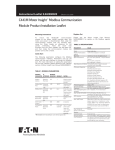
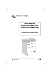
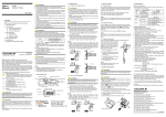
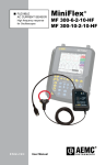
ENGLISH
User manual
1.800.561.8187
© Copyright HT ITALIA 2010
www.
.com
[email protected]
Release EN 1.00 - 22/02/2010
HT78
Table of contents:
1.
SAFETY PRECAUTIONS AND PROCEDURES ..........................................................2
1.1.
1.2.
1.3.
1.4.
2.
GENERAL DESCRIPTION ...........................................................................................4
2.1.
2.2.
3.
TRMS and MEAN VALUE measuring instruments............................................................ 4
TRUE ROOT MEAN SQUARE VALUE and CREST FACTOR definitions........................ 4
PREPARATION FOR USE ...........................................................................................5
3.1.
3.2.
3.3.
3.4.
4.
Preliminary ........................................................................................................................ 2
Before use ......................................................................................................................... 3
After use ............................................................................................................................ 3
Measuring (overvoltage) categories definitions................................................................. 3
Initial .................................................................................................................................. 5
Power supply..................................................................................................................... 5
Calibration ......................................................................................................................... 5
Storage.............................................................................................................................. 5
OPERATING INSTRUCTIONS.....................................................................................6
4.1.
Instrument description ....................................................................................................... 6
4.1.1.
4.2.
4.2.1.
4.2.2.
4.2.3.
4.2.4.
4.2.5.
4.2.6.
4.3.
General informations ....................................................................................................... 12
Batteries replacement ..................................................................................................... 12
Cleaning .......................................................................................................................... 12
End of life ........................................................................................................................ 12
TECHNICAL SPECIFICATIONS ................................................................................13
6.1.
Characteristics................................................................................................................. 13
6.1.1.
6.1.2.
6.2.
6.3.
Safety........................................................................................................................................ 13
General data ............................................................................................................................. 13
Environmental conditions ................................................................................................ 14
6.2.1.
Climatic conditions.................................................................................................................... 14
Accessories ..................................................................................................................... 14
6.3.1.
7.
AC Current measurement........................................................................................................... 9
Leakage current measurement on Single phase system ......................................................... 10
Leakage current measurement on Three phase system.......................................................... 11
MAINTENANCE .........................................................................................................12
5.1.
5.2.
5.3.
5.4.
6.
Range and ON/OFF selector...................................................................................................... 7
D-H key....................................................................................................................................... 7
FILTER selector.......................................................................................................................... 7
LOCK selector ............................................................................................................................ 7
AutoPowerOFF ........................................................................................................................... 7
DC analogical output .................................................................................................................. 8
How to perform the measurements ................................................................................... 9
4.3.1.
4.3.2.
4.3.3.
5.
Front panel.................................................................................................................................. 6
Description of parts ........................................................................................................... 7
Standard accessories ............................................................................................................... 14
SERVICE....................................................................................................................15
7.1.
7.2.
Warranty conditions......................................................................................................... 15
Service ............................................................................................................................ 15
1.800.561.8187
www.
EN.com
-1
[email protected]
HT78
1. SAFETY PRECAUTIONS AND PROCEDURES
This meter complies with IEC/EN61010-1. For your own safety and in order to avoid
damaging the instrument, you’re recommended to keep to the instructions contained in this
manual and read carefully all the notes preceded by the symbol .
Take extreme care for the following conditions while measuring:
• Do not measure voltage or current in humid or wet environment.
• Do not use the meter in presence of explosive gas (material), combustible gas
(material), steam or dust.
• Insulate yourself from the object to be tested.
• Do not touch exposed metal (conductive) parts such as sockets, fixing objects, circuits,
etc.
• If you detect anomalies of testing end (metal part) and attachment of the meter such as
breakages, deformations, foreign substances, no display, etc., do not take any
measurement.
The followings symbols are used on meter and user’s manual
Caution: refer to the instruction manual. An incorrect use may damage the tester
or its components.
High Voltage ranger: electrical shock risk.
Double insulated instrument.
AC Current
DC Voltage
1.1. PRELIMINARY
• This apparatus has been designed for use in an environment of pollution degree 2.
Indoor use
• It measures AC CURRENT on CAT II 600V or CAT III 300V plants. For overvoltage
and categories please see § 1.4
• You must comply with the usual safety regulations aimed at: protecting you against the
dangerous electric current and protecting the instrument against an incorrect operation
• Do not test or connect to any circuit whose current exceeds the specified overload
protection
• Make sure that the batteries are installed correctly
1.800.561.8187
www.
EN.com
-2
[email protected]
HT78
1.2. BEFORE USE
Always keep to the instructions contained in this manual:
CAUTION
Non compliance with the warnings and/or the instructions may damage the
tester and/or its components or injure the operator.
•
•
•
•
When the clamp is connected to the circuits to be tested, never touch unused terminals
When measuring current, any strong current near or close to the clamp jaw will affect
the accuracy
When measuring current, always put the tested conductor in the middle of the clamp
jaw in order to obtain a more accurate reading
If the reading value or the sign indication remains unchanged during the measurement,
check if the HOLD function is active
1.3. AFTER USE
• Once the measurements are completed, turn OFF the meter
• If you expect not to use the clamp for a long time, remove the batteries
1.4. MEASURING (OVERVOLTAGE) CATEGORIES DEFINITIONS
The norm IEC/EN61010-1: Safety requirements for electrical equipment for measurement,
control and laboratory use, Part 1: General requirements, defines what measuring
category, usually called overvoltage category, is. On § 6.7.4: Measuring circuits, it says:
(OMISSIS)
circuits are divided into the following measurement categories:
• Measurement category IV is for measurements performed at the source of the lowvoltage installation.
Examples are electricity meters and measurements on primary overcurrent protection
devices and ripple control units.
• Measurement category III is for measurements performed in the building installation.
Examples are measurements on distribution boards, circuit breakers, wiring, including
cables, bus-bars, junction boxes, switches, socket-outlets in the fixed installation, and
equipment for industrial use and some other equipment, for example, stationary motors
with permanent connection to fixed installation.
• Measurement category II is for measurements performed on circuits directly
connected to the low voltage installation.
Examples are measurements on household appliances, portable tools and similar
equipment.
• Measurement category I is for measurements performed on circuits not directly
connected to MAINS.
Examples are measurements on circuits not derived from MAINS, and specially
protected (internal) MAINS-derived circuits. In the latter case, transient stresses are
variable; for that reason, the norm requires that the transient withstand capability of the
equipment is made known to the user.
1.800.561.8187
www.
EN.com
-3
[email protected]
HT78
2. GENERAL DESCRIPTION
HT78 meter can performs the herewith features:
•
•
•
•
AC TRMS current measurement up to 3000A
AC leakage current measurement with 0.1mA resolution
DC voltage analogical output for connection with external data loggers
150Hz low-pass filter for reduce harmonic components of input signal
Each feature can be selected by using rotation selector on meter’s front panel. The Data
HOLD, FILTER and LOCK functions are still available (see § 4.2). The selected quantity
appears on a LCD display with indication of measurement units and functions. Analogical
bargraph it’s also displayed on meter. The meter disposes of an Auto Power Off function
consisting in an automatic switching off 10 minutes after last operation.
2.1.
TRMS AND MEAN VALUE MEASURING INSTRUMENTS
Safety testers for alternate quantities are divided into two big families:
• MEAN VALUE instruments: instruments which measure only the value of the wave at
the fundamental frequency (50 or 60 Hz).
• TRUE ROOT MEAN SQUARE instruments, also defined as TRMS: instruments which
measure the true root mean square value of the quantity under test.
In presence of a perfectly sinusoidal wave, both families provide identical results. In
presence of distorted waves, instead, the readings are different. Mean value instruments
provide only the value of the fundamental wave while True RMS instruments provide the
value of the entire wave, including harmonics (within the passband of the instrument).
Accordingly, if the same quantity is measured with both kinds of instruments, the
measured values are identical only if the wave is purely sinusoidal. Should it be distorted,
True RMS instruments provide higher values than medium value instruments.
2.2.
TRUE ROOT MEAN SQUARE VALUE AND CREST FACTOR DEFINITIONS
The current effective value is defined as follows: “In an interval of time equivalent to a
period, an alternate current with effective value having an intensity of 1A, by passing on a
resistor, disperses the same energy which would be dispersed in the same period of time
by a direct current having an intensity of 1A”. From this definition comes the numerical
1
expression: G=
T
t 0 +T
∫g
2
(t )dt The effective value is indicated as RMS (root mean square).
t0
The Crest Factor is defined as the ratio between the Peak Value of a signal and its
Gp
effective value: CF (G)=
. This value varies according to the waveform of the signal,
G RMS
for a purely sinusoidal wave it’s worth 2 =1.41. In presence of distortions the Crest Factor
assumes higher values as long as the wave distortion is higher.
1.800.561.8187
www.
EN.com
-4
[email protected]
HT78
3. PREPARATION FOR USE
3.1. INITIAL
The meter has been checked from a mechanical and electrical point of view before
shipment.
Every care has been taken to make sure that the instrument reaches you in perfect
conditions.
However, it’s advisable to make a rapid check in order to detect eventual damages which
may have occurred in transit. Should this be the case, enter immediately the usual claims
with the carrier.
Make sure that all the accessories listed in § 6.3.1 are contained in the package. In case of
discrepancies contact the dealer.
In case of returning of the tester please keep to the instructions given in § 7.
3.2. POWER SUPPLY
The instrument is batteries supplied. 2x1.5V type AAA LR03 are included in the package.
Battery life: about 200 hours. When batteries are low, the symbol “
” appears on the
display. Replace them immediately, following the instructions given in § 5.2
3.3. CALIBRATION
The tester complies with the technical features listed in this manual. Its performances are
guaranteed for one year.
3.4. STORAGE
In order to guarantee the accuracy of the measurements, after a period of storage in
extreme environmental condition, wait for the necessary time so that the tester returns to
normal measuring conditions (see environmental specifications, § 6.2.1).
1.800.561.8187
www.
EN.com
-5
[email protected]
HT78
4. OPERATING INSTRUCTIONS
4.1. INSTRUMENT DESCRIPTION
4.1.1. Front panel
LEGEND:
1.
2.
3.
4.
5.
6.
7.
8.
9.
Inductive clamp jaw
Holes for carrying straps
LOCK selector
Selector with
measurement ranges and
ON/OFF feature
Jaw trigger
FILTER selector
D-HOLD key
LCD display
DCV analogical output
terminal
Fig. 1: Instrument description
1.800.561.8187
www.
EN.com
-6
[email protected]
HT78
4.2. DESCRIPTION OF PARTS
4.2.1. Range and ON/OFF selector
Rotate the function selector from “OFF” position to any other position to turn on the meter.
Rotate again the selector to “OFF” position to switch off the meter
4.2.2. D-H key
Press D-HOLD key to enable Data HOLD feature. The “DH” message is shown and the
measured value is frozen on the display. Press the same key to exit from the function.
4.2.3. FILTER selector
Move the “FILTER” selector to enable (ON) or disable (OFF) the “Low-pass 150Hz filter”
during an AC current measurement. In this condition a low-pass filter with cut-off frequency
of 150Hz is active on meter in order to reduce the harmonic components of input signal. It
is reccomanded always to eneable this feature to perform accurate and stable
measurement of leakage current
4.2.4. LOCK selector
While slowly closing CT during the measurement on strong magnetic fields generated by
big currents, there might be a case where CT cannot be closed completely. In this case
use the LOCK selector to lock/unlock the jaws of clamp durino a measurement
4.2.5. AutoPowerOFF
In order to preserve the internal batteries, the meter automatically switch off after about 10
minutes of idleness. Press the D-H key or turn on again the meter after 10 second from
switch off to restore of normal functionality.
The AutoPwerOFF feature is automatically disabled by the meter during the connection to
DCV analogical output bt external datalogger
1.800.561.8187
www.
EN.com
-7
[email protected]
HT78
4.2.6. DC analogical output
The meter is designed with a DC voltage analogical output depending on the measured
current value and can be used for connection with external data loggers, digital
multimeters, etc.. (see Fig. 2) by using customized cables
CAUTION
Do not apply any vltage to the DCV output of metere durino the recording
operation
Fig. 2: Connection of meter with external logger
1. Select the desired measuring range and consider the herewith conversion values:
AC current range
300mA
3A
30A
300A
3000A
DC output voltage range
1mV/1mA
1mV/0.01A
1mV/0.1A
1mV/1A
1mV/10A
Table 1: Conversion values of DCV analogical output
2. Connect the external logger to the DCV output of meter
3. Perform the current measurement (see § 4.3)
1.800.561.8187
www.
EN.com
-8
[email protected]
HT78
4.3. HOW TO PERFORM THE MEASUREMENTS
4.3.1. AC Current measurement
CAUTION
Do not perform any AC current measurement on circuit with nominal voltage
higher to 500V to round to avoid possible electrical shocks and to damage
the meter
Fig. 3: Taking AC current measurement
1. Select a measurement range among the 3A, 30A, 300A or 3000A options
2. Move the FILTER selector on ON position to activate the “Low-pass 150Hz filter” (see §
4.2.3)
3. Open the clamp and put the conductor to be tested in the middle of the clamp jaw, then
reading will be displayed
4. For using of Data HOLD and see § 4.2.2. For using of analogical output see § 4.2.6
1.800.561.8187
www.
EN.com
-9
[email protected]
HT78
4.3.2. Leakage current measurement on Single phase system
CAUTION
Do not perform any AC current measurement on circuit with nominal voltage
higher to 500V to round to avoid possible electrical shocks and to damage
the meter
Fig. 4: Taking leakage current measurement on Single phase systems
1. Select the 300mA range on the meter
2. Move the FILTER selector on ON position to activate the “Low-pass 150Hz filter” (see §
4.2.3)
3. Open the clamp and put inside:
¾ The cables L1 and N if use the Differential method as shown in
¾ Fig. 4 obtaining the result as addition of instantaneous values of the currents flowing
in the wires
¾ The PE conductor if use the Direct method
4. The measured result is shown at display
5. For using of Data HOLD and see § 4.2.2. For using of analogical output see § 4.2.6
1.800.561.8187
www.
EN.com
- 10
[email protected]
HT78
4.3.3. Leakage current measurement on Three phase system
CAUTION
Do not perform any AC current measurement on circuit with nominal voltage
higher to 500V to round to avoid possible electrical shocks and to damage
the meter
Fig. 5: Taking leakage current measurement on Three phase systems
1. Select the 300mA range on the meter
2. Move the FILTER selector on ON position to activate the “Low-pass 150Hz filter” (see §
4.2.3)
3. Open the clamp and put inside:
¾ The cables L1, L2, L3 and N if use the Differential methos as shown in Fig. 5
obtaining the result as addition of instantaneous values of the currents flowing in the
wires
¾ The PE conductor if use the Direct method
4. The measured result is shown at display
5. For using of Data HOLD and see § 4.2.2. For using of analogical output see § 4.2.6
1.800.561.8187
www.
EN.com
- 11
[email protected]
HT78
5. MAINTENANCE
5.1. GENERAL INFORMATIONS
1. This clamp is an accured instrument. Whether in use or in storage, please do not
exceed the specification requirements to avoid possible damages or dangers.
2. Do not place this meter at high temperatures or humidity or expose it to direct sunlight.
3. Be sure to turn off the meter after use. If you expect not to use the tester for a long
time, remove the battery in order to avoid leakages of battery liquid that would damage
the internal parts.
5.2. BATTERIES REPLACEMENT
When “
” appears on the display, replace the batteries
WARNING
Only expert and trained technicians must perform this operation. Remove
the test leads or the conductor under test before replacing the battery.
1.
2.
3.
4.
5.
6.
7.
Switch off the meter rotate the selector in “OFF” position
Remove the cable from the jaws
Remove the screw from the battery cover, and detach the batteries cover
Remove the batteries
Replace batteries with a same type new one (see § 6.1.2). Take care to polarity
Replace the battery cover and screw
Use the appropriate battery disposal methods for Your area
5.3. CLEANING
For cleaning the instrument use a soft dry cloth. Never use a wet cloth, solvents or water,
etc.
5.4. END OF LIFE
CAUTION: this symbol indicates that equipment, its accessories and batteries
shall be subject to a separate collection and correct disposal.
1.800.561.8187
www.
EN.com
- 12
[email protected]
HT78
6. TECHNICAL SPECIFICATIONS
6.1. CHARACTERISTICS
Accuracy is indicated as [% rdg + (number of dgt) * resolution] referred to: 23°C(73°F) ±
5°C(41°F); RH< 80%
AC TRMS Current
Range
300mA
3A
30A
300A
3000A
Resolution
0.1mA
0.001A
0.01A
0.1A
1A
Accuracy
Bandwidht
±(1.5%rdg+ 8dgt)
50 ÷60Hz
Max input current
3Arms
30Arms
300Arms
3000Arms
±(2.0%rdg+ 8dgt)
DC analogical output
Range
300mA
3A
30A
300A
3000A
Resolution
1mV/1mA
1mV/0.01A
1mV/0.1A
1mV/1A
1mV/10A
Accuracy
Bandwidht
±(1.5% FS)
50 ÷60Hz
Max input current
3Arms
30Arms
300Arms
3000Arms
FS = full scale of any range
Internal filter
Type of filter
Low-pass
6.1.1. Safety
Comply with:
Insulation:
Pollution degree:
Max height:
Installation category:
Cut-off frequency
150Hz
IEC/EN61010-1, IEC/EN61010-2-032
double insulation
2
2000m (6562 ft)
CAT II 600V, CAT III 300V to the ground
6.1.2. General data
Mechanical characteristics
Size:
341(L) x 194(W) x 52(H)mm ; 13(L) x 8(W) x 2(H) inch
Weight (including batteries): 1.9kg (67 ounces)
Max conductor size:
108mm (4”)
Supply
Batteries type:
Low battery indication:
Battery life:
AutoPowerOFF:
2x1.5V alkaline batteries type AAA LR03
“
” symbol is displayed when the level is low
approx 200 hours of continuous use
approx 10 minutes of idleness
Display
Characteristics:
Sample rate:
Conversion mode:
Over range symbol:
4 LCD 3200 points plus decimal point, sign and bargraph
2 times/sec
TRMS
“O.L” indication at display
1.800.561.8187
www.
EN.com
- 13
[email protected]
HT78
6.2. ENVIRONMENTAL CONDITIONS
6.2.1. Climatic conditions
Reference temperature:
23 ± 5°C ; (73°F± 41°F)
Operating temperature:
0 ÷ 40°C ; (32°F ÷ 104°F)
Operating humidity:
<80%RH
Storage temperature:
-10 ÷ 60°C ; (-44°F ÷ 140°F)
Storage humidity:
< 80%RH
This product conforms to the prescriptions of the European directive on low voltage
2006/95/EEC (LVD) and to EMC directive 2004/108/EEC
6.3. ACCESSORIES
6.3.1. Standard accessories
The content of a standard package is the following:
• Instrument HT78
• Carrying bag
• Batteries
• Set of belt straps
• User manual
1.800.561.8187
www.
EN.com
- 14
[email protected]
HT78
7. SERVICE
7.1. WARRANTY CONDITIONS
This equipment is guaranteed against material faults or production defects, in accordance
with the general sales conditions. During the warranty period (one year), faulty parts may
be replaced. The manufacturer reserves the right to decide either to repair or replace the
product.
In case of returning of the instrument, all transport charges must be paid by the customer.
The instrument must be accompanied by a delivery note indicating the faults or reasons of
returning. The returned tester must be packed in its original box. Any damage occurred in
transit because of lack of original packaging will be debited to the customer.
The manufacturer is not responsible for any damage against persons or things.
Accessories and batteries are not covered by warranty.
The warranty won’t be applied to the following cases:
• Faults due to improper use of the equipment
• Faults due to combination of the tester with incompatible equipment.
• Faults due to improper packaging.
• Faults due to servicing carried out by a person not approved by the company.
• Faults due to modifications made without explicit authorisation of our technical
department.
• Faults due to adaptation to a particular application not provided for by the definition of
the equipment or by the instruction manual.
The contents of this manual cannot be reproduced in any form without our authorization.
Our products are patented. Our logotypes are registered. We reserve the right to
modify characteristics and prices further to technological developments.
7.2. SERVICE
If the equipment doesn’t work properly, before contacting the SERVICE, test the batteries
and change them if necessary.
If the equipment still doesn’t work, make sure that your operating procedure complies with
the one described in this manual.
In case of returning of the instrument, all transport charges must be paid by the customer.
The instrument must be accompanied by a delivery note indicating the faults or reasons of
returning. The returned tester must be packed in its original box. Any damage occurred in
transit because of lack of original packaging will be debited to the customer.
1.800.561.8187
www.
EN.com
- 15
[email protected]


![Procedure to Use Global Online Banking [PDF, Size: 1008.0KB]](http://vs1.manualzilla.com/store/data/005964624_1-7b8de4c8b1d722b3319a8c3c6d4449e7-150x150.png)