1
Final Report of Project Group 421
Project concubiNet
Daniel Barisic, Stefan Budde, Thomas Jung, Tobias Kneiphoff,
Nils Mirbach, Duy Nguyen, Michael Schlottmann, Marco Seine,
Stefan Träger, Gregor Wesolly, Lena Wiese
Holger Linde, Edwin Naroska, Jörg Platte, Peter Schramm, Peter Resch
Version 1.0, 30.09.2003
Contents
1
Contents
1 Introduction
6
1.1 Motivation . . . . . . . . . . . . . . . . . . . . . . . . . . . . .
6
1.2 Aims of the Project Group . . . . . . . . . . . . . . . . . . . .
6
1.3 Scenarios . . . . . . . . . . . . . . . . . . . . . . . . . . . . .
7
1.3.1 Saving Energy . . . . . . . . . . . . . . . . . . . . . .
7
1.3.2 Offshore Fire Protection . . . . . . . . . . . . . . . . .
8
1.3.3 Museum . . . . . . . . . . . . . . . . . . . . . . . . . .
9
1.3.4 Hotel . . . . . . . . . . . . . . . . . . . . . . . . . . . . 10
1.3.5 Intelligent TV . . . . . . . . . . . . . . . . . . . . . . . 11
1.3.6 Conclusion . . . . . . . . . . . . . . . . . . . . . . . . 11
1.4 Process Model . . . . . . . . . . . . . . . . . . . . . . . . . . 12
1.5 Technical Fundamentals . . . . . . . . . . . . . . . . . . . . . 13
1.6 Basic Concepts . . . . . . . . . . . . . . . . . . . . . . . . . . 13
1.6.1 Ubiquitous Computing . . . . . . . . . . . . . . . . . . 13
1.6.2 Ad-hoc Networking . . . . . . . . . . . . . . . . . . . . 14
1.7 Seminar Phase . . . . . . . . . . . . . . . . . . . . . . . . . . 14
2 Related Work
2.1 OSGi
15
. . . . . . . . . . . . . . . . . . . . . . . . . . . . . . . 15
2.1.1 Description . . . . . . . . . . . . . . . . . . . . . . . . 15
2.1.2 Conclusion . . . . . . . . . . . . . . . . . . . . . . . . 16
2.2 UPnP . . . . . . . . . . . . . . . . . . . . . . . . . . . . . . . 16
2.2.1 Components of a UPnP Network . . . . . . . . . . . . 16
2.2.2 Steps of UPnP Networking . . . . . . . . . . . . . . . 16
2.2.3 Conclusion . . . . . . . . . . . . . . . . . . . . . . . . 17
2.3 CORBA . . . . . . . . . . . . . . . . . . . . . . . . . . . . . . 17
2.3.1 IDL . . . . . . . . . . . . . . . . . . . . . . . . . . . . . 17
2.3.2 ORB 2 . . . . . . . . . . . . . . . . . . . . . . . . . . . 18
2.3.3 Conclusion . . . . . . . . . . . . . . . . . . . . . . . . 18
2.4 JINI and RMI . . . . . . . . . . . . . . . . . . . . . . . . . . . 18
2.4.1 JINI Surrogate . . . . . . . . . . . . . . . . . . . . . . 19
2.4.2 RMI (Remote Method Invocation) . . . . . . . . . . . . 20
2.4.3 Mini . . . . . . . . . . . . . . . . . . . . . . . . . . . . 21
Contents
2
2.5 JXTA . . . . . . . . . . . . . . . . . . . . . . . . . . . . . . . . 21
2.6 Routing Protocols for Ad-hoc Networks . . . . . . . . . . . . . 22
2.7 Distributed Operating System Architectures . . . . . . . . . . 22
2.8 Semantic Web . . . . . . . . . . . . . . . . . . . . . . . . . . 23
2.8.1 Overview . . . . . . . . . . . . . . . . . . . . . . . . . 23
2.8.2 Description . . . . . . . . . . . . . . . . . . . . . . . . 23
2.8.3 Conclusion . . . . . . . . . . . . . . . . . . . . . . . . 24
2.9 Bluetooth . . . . . . . . . . . . . . . . . . . . . . . . . . . . . 24
3 Concept
25
3.1 A Distributed Operating System . . . . . . . . . . . . . . . . . 25
3.2 Lookup System . . . . . . . . . . . . . . . . . . . . . . . . . . 25
3.3 Resource Control . . . . . . . . . . . . . . . . . . . . . . . . . 25
3.4 Surrogates . . . . . . . . . . . . . . . . . . . . . . . . . . . . 27
3.5 A “Sea” of Movable Objects . . . . . . . . . . . . . . . . . . . 28
3.6 Communication . . . . . . . . . . . . . . . . . . . . . . . . . . 30
3.6.1 Distributed Lookup . . . . . . . . . . . . . . . . . . . . 30
3.6.2 Central Lookup . . . . . . . . . . . . . . . . . . . . . . 32
4 Technologies
35
4.1 Introduction . . . . . . . . . . . . . . . . . . . . . . . . . . . . 35
4.1.1 Advantages of Re-Using Existing Code . . . . . . . . 35
4.1.2 Perspective “Open Source” . . . . . . . . . . . . . . . 35
4.1.3 Which Technologies are Used in concubiNet? . . . . . 36
4.1.4 Why Java? . . . . . . . . . . . . . . . . . . . . . . . . 36
4.2 JXTA, Our Root Technology . . . . . . . . . . . . . . . . . . . 37
4.2.1 The Peer-to-Peer Idea . . . . . . . . . . . . . . . . . . 37
4.2.2 Advantages of XML . . . . . . . . . . . . . . . . . . . 39
4.2.3 JXTA Protocols . . . . . . . . . . . . . . . . . . . . . . 39
4.3 XML-RPC . . . . . . . . . . . . . . . . . . . . . . . . . . . . . 40
4.3.1 XML-RPC spec and the binding for JXTA . . . . . . . 41
4.3.2 How It is Used in concubiNet . . . . . . . . . . . . . . 42
4.3.3 Conclusions after Working with It . . . . . . . . . . . . 42
Contents
3
5 Architecture
44
5.1 Conventions . . . . . . . . . . . . . . . . . . . . . . . . . . . . 44
5.2 Analysis . . . . . . . . . . . . . . . . . . . . . . . . . . . . . . 44
5.2.1 Hardware Layer . . . . . . . . . . . . . . . . . . . . . 44
5.2.2 Middleware - concubiNet - and Application Layer . . . 45
6 Implementation
46
6.1 Agent . . . . . . . . . . . . . . . . . . . . . . . . . . . . . . . 47
6.1.1 Configuration . . . . . . . . . . . . . . . . . . . . . . . 48
6.1.2 Joining concubiNet . . . . . . . . . . . . . . . . . . . . 48
6.1.3 Transfer of CCN-objects . . . . . . . . . . . . . . . . . 49
6.1.4 Classloader Concept . . . . . . . . . . . . . . . . . . . 50
6.1.5 Finding or Creating Advertisements . . . . . . . . . . 51
6.1.6 Finding Neighbouring Agents in the concubiNet Peer
Group . . . . . . . . . . . . . . . . . . . . . . . . . . . 52
6.1.7 Registration/Deregistration . . . . . . . . . . . . . . . 52
6.1.8 Communication . . . . . . . . . . . . . . . . . . . . . . 52
6.1.9 LUS-Integration . . . . . . . . . . . . . . . . . . . . . . 53
6.1.10 Starting a Central LUS . . . . . . . . . . . . . . . . . . 54
6.2 CCN-object . . . . . . . . . . . . . . . . . . . . . . . . . . . . 54
6.2.1 Remote Communication . . . . . . . . . . . . . . . . . 54
6.2.2 Wrapper and Serialization . . . . . . . . . . . . . . . . 55
6.3 LUS . . . . . . . . . . . . . . . . . . . . . . . . . . . . . . . . 56
6.3.1 Query . . . . . . . . . . . . . . . . . . . . . . . . . . . 57
6.3.2 SearchTree . . . . . . . . . . . . . . . . . . . . . . . . 58
6.3.3 ClassNode . . . . . . . . . . . . . . . . . . . . . . . . 61
6.3.4 ObjectInfo . . . . . . . . . . . . . . . . . . . . . . . . . 62
6.3.5 Central LUS . . . . . . . . . . . . . . . . . . . . . . . . 63
6.3.6 Central LUSWrapper . . . . . . . . . . . . . . . . . . . 64
6.3.7 AttributeList . . . . . . . . . . . . . . . . . . . . . . . . 64
6.4 LBS . . . . . . . . . . . . . . . . . . . . . . . . . . . . . . . . 65
6.4.1 Load Balancing Service . . . . . . . . . . . . . . . . . 65
6.4.2 Statistical Information . . . . . . . . . . . . . . . . . . 65
6.4.3 Retrieving CCN-object Size . . . . . . . . . . . . . . . 65
6.4.4 Retrieving Method-Calling-Times . . . . . . . . . . . . 65
Contents
4
7 Conclusion
67
8 User’s Manual
68
8.1 Configuration . . . . . . . . . . . . . . . . . . . . . . . . . . . 68
8.1.1 Configuration Items . . . . . . . . . . . . . . . . . . . 68
8.1.2 The HotConfiguration Feature . . . . . . . . . . . . . . 69
8.2 Agent-GUI . . . . . . . . . . . . . . . . . . . . . . . . . . . . . 69
8.2.1 Goal and motivation of the Agent-GUI . . . . . . . . . 69
8.2.2 Information about the Agent . . . . . . . . . . . . . . . 69
8.2.3 Wrapperlist . . . . . . . . . . . . . . . . . . . . . . . . 70
8.2.4 Transfer Object . . . . . . . . . . . . . . . . . . . . . . 70
8.2.5 About concubiNet . . . . . . . . . . . . . . . . . . . . 71
8.3 ChatGUI - concubiChat . . . . . . . . . . . . . . . . . . . . . 71
8.3.1 Chat Tab . . . . . . . . . . . . . . . . . . . . . . . . . 71
8.3.2 Search Tab . . . . . . . . . . . . . . . . . . . . . . . . 72
8.3.3 Info Tab . . . . . . . . . . . . . . . . . . . . . . . . . . 74
8.3.4 Event Tab . . . . . . . . . . . . . . . . . . . . . . . . . 74
8.3.5 Misc Tab . . . . . . . . . . . . . . . . . . . . . . . . . 76
9 Developer’s Manual
76
9.1 Introduction . . . . . . . . . . . . . . . . . . . . . . . . . . . . 76
9.2 Basics . . . . . . . . . . . . . . . . . . . . . . . . . . . . . . . 77
9.3 Wrapper . . . . . . . . . . . . . . . . . . . . . . . . . . . . . . 77
9.3.1 Constructor . . . . . . . . . . . . . . . . . . . . . . . . 77
9.3.2 Methods . . . . . . . . . . . . . . . . . . . . . . . . . . 78
9.4 CCN-object . . . . . . . . . . . . . . . . . . . . . . . . . . . . 80
9.4.1 Delegate . . . . . . . . . . . . . . . . . . . . . . . . . 80
9.4.2 Construction . . . . . . . . . . . . . . . . . . . . . . . 81
9.5 Eventing . . . . . . . . . . . . . . . . . . . . . . . . . . . . . . 81
9.5.1 Listener . . . . . . . . . . . . . . . . . . . . . . . . . . 82
9.5.2 Eventgenerator . . . . . . . . . . . . . . . . . . . . . . 82
References
84
Contents
5
Abstract
This document describes the progress of our project work throughout the years 2003/2003 and presents the results we have achieved.
The idea of our project was to plan, design and develop an operating system for ubiquitous computing which is capable of sharing and
distributing resources throughout the network. Software objects are
able to automatically move from one device in a network to another
device without disrupting the normal workflow of the programms running. This builds an abstract layer above the network. As the objects
can communicate with each other without knowing where they are.
It makes programs and their modules or objects independent of the
place where they are executed. They can be freely transferred in the
network, running at the place which is suited best for them according
to load balancing, resource usage and network latency time.
At first the technical feasibility study on techniques and methods for a
basic foundation of concubiNet point out that we should relay on technologies like UML, Java and JXTA for our project. Our attention was
turned to JXTA, because it is an excellent choice as our core platform
for communication in the concubiNet network. It realizes a platformindependent way of creating a peer-to-peer network.
To target the aspect resource management we developed the idea of a
"sea" of movable objects. This means that single objects can be transferred freely within the network in order to achieve a load balanced
network finally and to support movability of CCN-objects in the concubiNet. As this "sea" can be seen as an abstract layer above the network, we had to implement mechanisms for objects to find each other.
Thus the first high level service, the LUS (lookup service), has been
integrated into the concubiNet system. It is a central service allowing
CCN-objects to find each other within the network.
Creating an operating system, we had to consider several aspects as
it has to be capable of, e.g. resource allocation, memory management
and security. During our work we focussed on the implementation of
fundamentals relating to these aspects. The basic services for building
a high level service framework coordinating resources were realized.
The aspect of security has not been dealt with at all, since the other
aspects had a higher priority in the first place.
After one year of work in our project group, we finished with a specification of the whole system and an implementation of all basic services
that our operating system should be capable of. Drawing the conclusion it can be said that the system works fine in the way it was intended
to. Some of the technologies proved as not being the best solution for
our system, i.e. XML-RPC, as it does not support all types of Objects
that we need to transfer through the network and it takes a great deal
of time using timeouts and other flaws. For the following project group
working on concubiNet the task is to evaluate the techniques we have
used and maybe replace them by own implementation where needed
to improve system performance.
1
Introduction
1
1.1
6
Introduction
Motivation
With regard to ubiquitous computing small computers and microcontrollers
in ordinary technical tools are used to make their services available in wired
or wireless areas. The goal is to improve convenience and efficiency for
the human user. The base for implementing such an environment is a
distributed operating system, that is able to manage different types of devices. Due to the heterogeneity of hardware interoperability becomes an
important aspect, especially in the context of mobile and wireless communication.
Looking at in-house networks as an example, the remote control of devices
like lights or heaters with a cell phone or PDA is an interacting application.
Thinking further, applications that handle some requests automatically are
imaginable, for example an automated light control system, that dims the
light in accordance to different user profiles. This goes hand in hand with
the function of location awareness. In addition to that, context awareness
is useful, if the system is able to decide between alternatives according to
the time of day or the actual temperature outside for example.
As complex applications must be executed to build such a smart environment, a system would be useful that makes efficient use of all available
resources in the network. Hence, some kind of intelligent resource management is required. Just imagine the possibility of moving tasks from
smaller devices (e.g. PDA) to bigger machines (PC) automatically. It is
just a matter of being connected to the same net by a smart operating system. Even moving objects – i.e., parts of applications – is thinkable. Thus
applications that need very much memory can be moved object by object
to other machines and still fulfill their task. As this works absolutely automatically, the user will never know about these things, which is the most
convenience an operating system can provide.
1.2
Aims of the Project Group
There are different types of communication protocols and middleware solutions, which can be used to realize the described features. The problems
emerge with the integration of heterogeneous devices. Thus the following
problems are the main ones to be solved:
• Joining complex groups for ad-hoc networking needs a lot of resources
in several aspects as power, memory and energy. With regard to
mass production or small battery devices this is not acceptable.
• The interaction of different systems implementing ubiquitous computing protocols is not practically working. This results from incompatibility of physical interfaces and different communication protocols.
Thus, the general goal of this project group is the development and implementation of a distributed operating system for ubiquitous computing and
ad-hoc networking. This goal includes the construction of a homogeneous
communication platform and the implementation of an operating system
1
Introduction
7
“above” this platform.
This operating system has to provide several services that are needed to
implement the features mentioned above. First of all, there has to be some
kind of mechanism that allows the movement of objects from machine to
machine. Based on this, an intelligent resource management can be implemented, which is able to decide whether it is necessary or useful to move
certain objects, where to move these objects and when to move these objects. Going hand-in-hand with this is a solution for the integration of different devices that use different communication protocols.
It emerges that there are several parts to work on, that will finally form the
operating system. It is therefore necessary to decide which parts of the
OS are more essential then others and which parts can be added at a later
time. To support these decisions we built scenarios that should help to
identify the main aspects of an appropriate operating system.
1.3
Scenarios
In order to get a more precise idea of the project goals, the first step was the
creation of scenarios in which the use of a concubiNet could make sense.
These scenarios were used to discuss the main features a concubiNet operating system must have. For a better understanding of how this process
worked the scenarios are presented below.
1.3.1
Saving Energy
This scenario takes place in a house or a flat with a concubiNet system.
As it is winter the mornings are cold and dark. The intelligent concubiNet
radiator starts heating the rooms shortly before the alarm clock rings and
the family gets up. During the night it automatically is set to energy saving
mode. It also notices that the bedroom windows are openend now to air the
room and for that reason it excludes the bedroom from its heating profile.
The father gets up to prepare the breakfast. The concubiNet coffee machine can be turned on from anywhere in the house and so father can
activate it while he is in the bathroom. The coffee machine also will notice
when the coffee pot is empty and therefore turn itself off. In the bathroom
water usage can be controlled by the concubiNet system. A profiling mechanism can control water temperature and filling level of the bath tub.
The rest of the family has got up in the meantime. A room is instantly
illuminated when a person enters and light and other electric devices that
are not in use will be turned off when the person leaves the room again.
After breakfast all the family leaves the house to go to work or to school.
The concubiNet system notices their leaving and runs a checking routine
to power down electric appliances and radiators.
The inhabitants can program the concubiNet system to prepare for their
coming home (e.g. heating or cooking) and it also can be remotely accessed to check the house’s state.
In the evening mother completes her working-day in the workroom while
the rest of the family is watching TV. By the time she finishes her work and
1
Introduction
8
joins her family. Thereupon all lamps at her desk go out.
At the end of the day all family members go to bed and concubiNet runs a
checking routine to set the house to “night” status.
1.3.2
Offshore Fire Protection
Prevention of a blaze:
It is the aim of every good fire protection system to recognize a fire at the
very beginning in order to prevent a blaze of spreading to a larger extend.
concubiNet could be a helpful tool in such a system.
Imagine the following scenario:
In one of the lower levels of an oil rig or maybe at any other extremely
fire-endangered place, a fire breaks out. In this early stadium it is still
easily to be brought under control, but time is the critical factor. One maybe
would not be able to control the fire after the alarm sounded and the fire
extinguisher team arrived at this place. It would be a lot better in terms
of the critical time, not so send a specialized fire extinguisher team to the
place but just the nearest qualified team or worker which is available. This
worker or team could quickly reach the place of the fire and extinguish it.
How can this be realized?
First of all, highly sensitive fire detectors are needed, which inform the
alarm system about the existence and the location of a fire. These fire
detectors should be available on every oil rig nowadays. Furthermore, every worker on the rig has to carry a mobile device with him which can be
used for localization and identification. This could be a PDA or a kind of
cell phone device. PDA devices are usually common today on oil rigs but
need to be extended with a localization ability. Futher it is necessary to get
information about the qualification of each worker with respect to fire fighting. Only then, the nearest qualified man can be found when a fire breaks
out.
Ideally, an example case would look like this:
A paper basket caught fire. Imagine a gas pipe running above the basket.
Fire detectors in the ceiling recognize the fire and the imminent danger
in the case that the fire would spread towards the gas pipe. The system
realizes the critical situation and tries to localize a worker nearest to the
fire place. If a worker or a group of workers is found, their qualification for
fire fighting is checked, and if positive, they are informed about the fire and
asked to take over this task. If they (or he) answer with a positive reply the
system can give them more information about the position of the next fire
extinguisher or maybe information about some dangerous materials in the
room of the fire. It is now primarily the task of this worker or of this group to
extinguish the fire, but the system can also inform other people in order to
support the first team.
Containment and damage reduction:
A further development of the idea above is damage reduction. The system
should be able to decide whether it is better to try to extinguish a fire or
to take other means of fighting the spreading of the fire. Think of following
example: A fire starts in a room with no critical importance for the platform.
The fire could for instance begin in the caboose and it might not be possible
1
Introduction
9
to quickly fight the fire. In this situation it could make sense not to transfer
the task of extinguishing the fire to a group of workers and send them to this
location but to accept a small damage and to embank the fire by shutting
some airtight doors around this room, and by doing so, spatially limiting the
damage of the fire.
How could this be realized?
The system would have to be outfitted with enough intelligent functionality
for evaluating the danger of a situation and for taking and suggesting further
steps. Then, there would have to be facilities for spatially limiting a fire, like
fire resistant and airtight doors and locks. Those must be able to be shut
by the system in order to lock certain areas. Like in the example above, it
is also necessary for each worker to carry a PDA-like or some other device
with him for means of localization.
An example case could look like this now:
Imagine the start of a blaze in the caboose. Fire detectors recognize the fire
and size of the fire by the temperature, smoke development and size of the
burning area. They reckon that the fire is already too big to easily extinguish
it. The system gives alarm and checks wether it is possible to contain the
fire. Therefore, the system first checks the location of all neighbouring fire
doors and locks and if the area which could be shut and enclosed by them
is too large or contain any critical resources. It is important, before closing
any doors, to check the location of the workers in that area, if any. This
makes it necessary for every worker to have its mobile device with him at
all times, otherwise it could be possible that a worker is captured or injured
by the fire. The system continues, if it does not get a positive response by
every worker from his device after the alarm sounded. So, for ensuring that
no worker will be captured by closing the fire doors in a certain area every
worker will have to uniquely identify himself and his location with his mobile
device and for instance a fingerprint scan. After the system can be sure
that it could close the fire doors without further danger it could proceed and
lock the area and try to suffocate the fire by withdrawal of oxygen or just
hinder the fire from further propagation until a fire-fighter team arrives.
Rescue and personal security:
Surely, sometimes it will not be possible to bring a fire under control again.
In any case, persons will probably be in danger. In this case, the system
could help rescuing people.
Imagine a quickly spreading, huge fire, which cannot be brought under
control. Then, all persons have to be led out of the danger zone, either by
a rescue team or by themselves using escape routes. The system should
help the rescue team to locate persons who maybe cannot escape by themselves. It should inform the team about the location and also about the vital
condition of people in danger. Those people who still can move on their
own should be informed about the nearest escape routes without having to
know or read a complicated escape plan.
1.3.3
Museum
Mr. and Mrs. Müller take a walk through their local shopping mall and their
concubiNet (CCN)-ready devices are adjusted to receive advertisements.
1
Introduction
10
As they pass the museum, a message is delivered giving a short list of current exhibitions.
Because they are interested in arts, they decide to visit the museum and to
join its concubiNet. Therefore the CCN gathers standard personal information like age and sex in order to analyse them. In addition to this, both get a
questionnaire to tell the CCN about their special interests in this museum.
After have been offered a specialized tour through the museum based on
their personal information, Mr. and Mrs. Müller decide to take different tours
and pay them electronically. In order to find each other later, they both allow each other, to view their progress on the tour and the current position
in the museum by the CCN. Using the same mechanism is it possible to
locate service employees of the museum, who all own a CCN device, e.g.
for the purpose of asking questions or getting help.
Now Mr. and Mrs. Müller are ready to start their tour. Unfortunately Mrs.
Müller just owns a CCN-ready mobile phone, which has no high resolution
display, so the tour is described to her by text. In addition to this she is
guided by smooth lightened arrows on the ground and on the walls. Mr.
Müller on the other hand owns a PDA, which makes it possible for him to
display a map of the museum showing his current position. That’s why he
needs no guiding lights. When standing in front of a painting, he gets basic
information about this piece of art and its artist immediately. If desired, he
is able to check hyperlinks to the internet or watch movies to get additional
information. Because it would be too much to study all this information in
the museum, he decides to send this data to his email account for a little fee. Furthermore Mr. Müller is able to change his tour when noticing
e.g. that he likes a particular artist better, so more emphasis is laid on this
artist. At the same time Mrs. Müller arrives at the most famous part of
the exhibition, which is secured by a special entrance door. She already
paid for that part of the exhibition at the beginning, so the door is opened
automatically for her. Mr. Müller’s tour is over now, so he checks his PDA
for his wife’s progress on her tour and how long it approximately will last.
He finds out, that he has plenty of time, therefore he displays the nearest
restroom and the small restaurant he noticed at the beginning. Just when
Mr. Müller finishes eating his sandwich, his wife arrives from her tour and
they decide to leave the museum. On their way out they receive a short
message about upcoming exhibitions, which match their special interests.
This data is stored in the net of the museum, because this way the museum
is able to generate matching offers the next time Mr. and Mrs. Müller walk
by the museum as well.
1.3.4
Hotel
Finally there! After several hours of travelling Mark and Joan arrive at their
final destination. A small very nice hotel in the middle of Istanbul is waiting
to be a comfortable home for the next two days for them.
To make things easier they have already offered some personal information
about them during booking. So Mark gets direct access to the LAN inside
the hotel when entering, because the local concubiNet directly integrates
his PDA into the local net.
Thus Mark is able to get information about the check-in and the whole hotel.
The check-in is half-automated now, so that Mark and Joan just have to
1
Introduction
11
add some missing information about them on a touchscreen terminal. After
deciding about the type of payment the terminal presents their chip card,
which acts as key and localisator. Thus it is much easier for the cleaning
personnel to know when to tidy up the room and when not to disturb the
customers.
In their room Mark has the possibility to manage all components in the
room with his own interface on his PDA. Thus there is no change to the
normal usage at home. At Joan’s wish he changes the room temperature
to 25 degrees and orders the bath-tub to be filled with water at 38 degrees.
While Joan is happily having a bath, Mark starts the interactive hotel-TV to
get information about the town and the sights. After a while he has placed
them together to a tour, which was automatically booked over the TV.
All relevant information and maps are parallelly loaded up on his PDA, so
that he has the possibility to locate everything via GPS.
Happy holiday...
1.3.5
Intelligent TV
After a long day of work Hans returns home and enters his living room. The
TV switches on. While the latest news appear, in the upper right corner of
the screen a little window pops up delivering the message, that the washing
machine has finished its work.
Right after his washing is on the line he wants to relax a bit by watching
some TV. Because Hans likes to watch thrillers the device shows him a list
of the thrillers that have been on air today. Hans selects one of them and
the device plays it. When suddenly in the late afternoon sun shines at the
TV screen, the device forces the system to draw the curtain.
Hans just made himself comfortable when someone rings the door bell.
The screen freezes and a little window with a video from the camera at
the front door pops up: Good news, it is just Klaus, the fork-lift driver, who
invited himself for some bottles of beer.
By a menu on the screen Hans uses the electric door opener. Hans decides to watch the rest of the film tomorrow and so the device records the
remaining part of the movie.
1.3.6
Conclusion
Considering the scenarios above several desired features for a system can
be summed up:
• Object orientation
• Management of profiles
• Location awareness
• Interface awareness
• Authentification
• Security
1
Introduction
12
These are examples of services which might be implemented in future into
our system. As shown by this list, there are signigicant computational resources required in order to implement such a smart environment. While
the total computing power of the distributed resources within an ubiquitous
computing network may become significant, an operating system is needed
to efficiently make use of these resources in order to work as a base for a
smart environment. Hence, a fundamental platform had to be created first.
This was the aim of PG 421.
1.4
Process Model
For the development of concubiNet, we had to choose a process model for
the software engineering process. Starting from theoretical models combined with our own experiences in software engineering processes, we decided to use an iterative and incremental model which is a consequent
enhancement to the waterfall model. This model best supports the objectoriented development.
concubiNet was planed to be implemented in three iteration steps. The first
one included the technical feasibility study on techniques and methods for a
basic fundament of concubiNet. Afterwards the second iteration aimed at a
very minimal concubiNet communication platform as a prototype resulting
in a milestone. Finally in the third iteration, our desired concubiNet features
are to be implemented based on the prototype.
In every iteration the long-term objective was always the end of the third
iteration. The advantage in partitioning the software engineering process
into three parts is that the whole development processes can be kept more
clearly arranged.
Each iteration step consisted of the following process parts:
• use cases
• specifications
• activity diagrams
• object-oriented analysis
• sequence diagrams
• object-oriented implementation
• testing and validation
We must admit, that due to to the long technology study and the short time
that was left for the implementation, we shortened the first five steps of
the third iteration and only updated necessary documents in these steps.
Otherwise we realized the planned three iteration steps.
In order to produce a software project, which might further be developed
by different developers, the documentation of the software system process
should be as precise as possible. Especially the Java-code was to be documented well with the use of JavaDoc in english language.
For monitoring the resulting documents and documentations one member
of the project group took the role of a quality manager. The final review of
the resulting documents was done by the tutors.
1
Introduction
1.5
13
Technical Fundamentals
For the first development processes we used the application Together [2].
By using Together, we modeled the specification of the concubiNet project
in Unified Modelling Language (UML). UML is the industry standard language for specifying, visualizing, constructing, and documenting the artefacts of software systems. It simplifies the complex process of software
design, making a "blueprint" for construction.
concubiNet is implemented in the programming language Java SE Version
1.4.1 [3] from Sun Microsystems. This choice has the advantage that the
resulting software product basically is platform independent.
For developing with Java we used eclipse [5] as an Integrated Devopment
Environment (IDE). This IDE is a software project developed as open source
and is distributed free of charge.
The fundamental communication platform for concubiNet is JXTA [6]. JXTA
technology is a set of open protocols that allow any connected device
on the network ranging from cell phones and wireless PDAs to PCs and
servers to communicate and collaborate in a peer-to-peer manner. More
information about JXTA can be found in section 2.5 on page 21.
We used the hardware infrastructure of the RETINA computer pool at the
electrical engineer department. The provided hardware were Personal
Computers with Pentium IV processors and 512 MB RAM.
1.6
Basic Concepts
1.6.1
Ubiquitous Computing
The term ubiquitous computing in its current form, was first articulated by
Mark Weiser in 1988 at the Computer Science Lab at Xerox PARC. He
described it with these words:
“Inspired by the social scientists, philosophers, and anthropologists at PARC, we have been trying to take a radical look at
what computing and networking ought to be like. We believe
that people live through their practices and tacit knowledge so
that the most powerful things are those that are effectively invisible in use. This is a challenge that affects all of computer
science. Our preliminary approach: Activate the world. Provide
hundreds of wireless computing devices per person per office,
of all scales (from 1" displays to wall sized). This has required
new work in operating systems, user interfaces, networks, wireless, displays, and many other areas. We call our work "ubiquitous computing". This is different from PDA’s, dynabooks, or
information at your fingertips. It is invisible, everywhere computing that does not live on a personal device of any sort, but is
in the woodwork everywhere.”
So, ubiquitous computing is a completely another point of view how electronic devices are used to support the human life. The use of a service of
such a device should be implicit and should be possible everywhere. More
from Mark Weiser about this new point of view can be found in [7] and [8].
1
Introduction
14
1.6.2
Ad-hoc Networking
In the past, networking was always combined with a physical network structure like bus, ring or star topology. With the development of more mobile
devices instead of stationary computers, the need for more flexible network
topologies grew. As a result of this, wireless network systems became
more famous. The main characteristic of the first wireless networks is the
use of one or more access points, to which the mobile computers connect
via special wireless protocols. Now the users of such a network are able
to move unattachedly within the physical range of a wireless network. The
remaining disadvantage of such an conventional access point network system is unflexibility. Imagine two or more computers convene and want to
exchange data. For this scenario ad-hoc networking is the solution.
Ad-hoc networking describes a wireless, self organizing network, which
needs no fixed infrastructure. The devices participating in ad-hoc networking are called nodes. Once a node enters the transmitting range of another
node, the two nodes are able to communicate with each other. With more
sophisticated realizations of ad-hoc networking protocols even two nodes
of an ad-hoc network which cannot exchange data directly, can communicate in a multi-hop manner with the use of other nodes between them.
More information about routing in ad-hoc networks can be found in section
2.6 on page 22.
1.7
Seminar Phase
Previous to the beginning of the project group, it was necessary for all members of the group to have the same basic knowledge level about the subject
of our work. Furthermore we needed to decide about the fundamentals of
concubiNet and what communication infrastructure we are going to use.
Not to mention the need for everyone to get to know the rest of the group.
The Seminar took place from Fr. 11.10.2002 to Su. 13.10.2002 in the “Universitätskolleg Bommerholz” in Witten-Bommerholz, which is associated to
the University of Dortmund.
Every member of our project group had been assigned a special topic,
which was to be presented during the seminar weekend. For each topic, a
lecture of about half an hour was given with the possibility to comment and
discuss afterwards. In addition to this, a more detailed paper with a volume
of about ten pages was written on every topic.
The most numerated technologies of the Related Work section 2 give a
short review of these topics. The more detailed paper versions and the presentation versions (both in German) can be downloaded from our projectpage – http://www.concubinet.org.
2
Related Work
2
15
Related Work
The main idea of a distributed network with small devices, such as PDA,
mobile telephone, set top box or the like, is not new and many projects are
dealing with this idea. The following text will give a review of these projects
and it should be made clear that there are many different approaches and
solutions. To start with, OSGi is a prototype of a central administrated
network, which the user cannot interact with. The complete administration would be delivered by the OSGi infrastructure. Such a system also
allows networks where no administrative knowledge exists. JINI is a technology from Sun Microsystems. JINI enables a communication platform for
small devices in an ad-hoc network. Another approach is UPnP, which was
mainly created to extend the idea of PnP hardware installation to networks.
In addition to these approaches there are some technologies which can
be used in a distributed network. RMI and CORBA enable the creation of
distributed applications. RMI is a pure Java extension and CORBA is a
language independent solution. In this section we also introduce the JXTA
project. JXTA is the fundamental part of the concubiNet project. At the
end of this section we will give a short review of the concept of distributed
operating systems, the concept of routing in an ad-hoc network, the concept of semantic web and Bluetooth. These things are related works in the
broadest sense.
2.1
OSGi
The Open Services Gateway initiative (OSGi) (see [9]) was founded by
a group of electrical equipment manufacturers, telephone companies and
others in 1999. Its aim was to develop a “service delivery standard” between in-house networks and Wide Area Networks or the Internet.
This standard should mainly provide remote access to the home network
via cell phones or internet. E-Services will automatically be downloaded to
your local network from so called E-Service provider sites.
To run the net no administration from the user side is needed.
2.1.1
Description
All the house’s devices are connected to a gateway (additionally mobile or
radio devices are connected to their base station and the base station is
connected to the gateway). The software necessary on the gateway is an
OSGi server like SUN’s Java Embedded Server (JES).
The gateway has a permanent connection to a gateway operator, which
is a trustable organization that controls all communication from and to the
gateway. This means also remote access to the home net is controlled by
the gateway provider.
Every OSGi server consists of a framework where it puts its E-Services in a
modular form. E-Services, the so called bundles, are JAR archives. These
archives contain not only the service byte code but additionally graphics
and other files needed to offer the E-Service.
2
Related Work
16
2.1.2
Conclusion
As OSGi uses a base station, a gateway and a gateway operator, it is not a
distributed system. The net wouldn’t operate without an instance of each.
The centralized structure of OSGi doesn’t match the favoured design of a
distributed system for concubiNet. In addition the work on OSGi seems
to be discontinued. Only the idea to communicate over different kinds of
communication channels will be included in the design of concubiNet.
2.2
UPnP
The introduction of PnP has revolutionized the hardware installation. The
target of UPnP was to bring a unified installation mechanism to a network.
It is based on the TCP/IP Protocol. It makes the possible the intergration of
different devices into the network without any kind of administration.
2.2.1
Components of a UPnP Network
Devices Devices are pooled to working groups, which own a standardized bunch of services (e.g. printers). Besides information about their
services, properties such as name or manufacturer, are stored in an XML
document, provided by one device of that working group.
Services The smallest unit of control in a UPnP network is a service. This
service provides activities and describes its state using state variables. A
service in a UPnP device consists of a state table, a control server and
an event server. The state table models the state of the service through
state variables and updates them when the state changes. The control
server receives action requests, executes them, updates the state table
and returns responses. The event server publishes events to interested
subscribers whenever the state of the service changes.
Control Points A control point in a UPnP network is a controller capable
of discovering and controlling other devices.
2.2.2
Steps of UPnP Networking
Adressing Every device in the UPnP network has to use a DHCP (Dynamic Host Configuration Protocol) client and looks up a DHCP server
when joining the network. That way an IP address is provided, otherwise
AutoIP is used. If the device is capable of providing higher layer protocols,
DNS systems can be used additionally.
Discovery If addressing has taken place successfully, the discovery using SSDP follows. In this case a device publishes its services to a control
point. The control point itself can look up devices of interest using SSDP.
Any communication is performed using control messages containing information about services or devices such as names or links to XML description
documents.
2
Related Work
17
Description The next step in UPnP networking is called description. A
control point connected to the network does not know very much about the
devices he found. In order to get additional information he can request
XML description documents containing data about embedded devices or
services.
Control To control a device the control point sends a control request to
the control URL of the service of interest. These XML messages are delivered via SOAP.
Eventing The description of a service consists of a list of possible activities as well as a list of state variables. A service publishes updates of its
state tables through the network. A control point interested in changes can
subscribe there. A special initial event notification containing names and
values of evented variables is used when a control point joins the network
for the first time. In order to support several control points, event notifications concerning all evented variables are sent to every subscriber, even if
one of these variables has not changed.
Presentation If a device has a URL representing the device, a control
point is able to retrieve a document from this location and depending on
the properties of this control document the control point can see the state
of the device or it can even control the device.
2.2.3
Conclusion
The techniques of UPnP ought to integrate devices into the network fully
automatically. This speeds up the installation time and lowers the needed
knowledge of the user. With XML as the description language it is open
to incorporate new services. ConcubiNet wants to control and integrate
devices, too. Its main usage is not to expand an existing network with new
devices, but unlike UPnP it will connect different standards to each other,
too.
2.3
CORBA
The Common Object Request Broker Architecture is a middleware, which
was specified in 1989 by the OMG. The goal of this organization is to specify a framework which helps to develop distributed and heterogeneous systems easier. The core of this architecture is the Object Request Broker
(ORB), which is a universal communication medium between any different
objects in a distributed network. Middleware systems in general have the
purpose to simplify development of a distributed system through an abstraction layer. The agent for the client is called stub, the one for the server
side skeleton.
2.3.1
IDL
The main reason for the platform independence of CORBA is that the whole
communication between the distributed objects is translated into a specific
language. The language is named IDL (Interface Description Language).
2
Related Work
18
The communication protocol is based on TCP/IP. Stubs and skeletons are
generated automatically from the IDL source code through the IDL compiler. The developer is free to choose the language, he or she will use. It is
even possible to choose different languages for the client and server side of
the application. The developer must describe only the objects, which must
be accessible by other distributed objects, through a IDL specification. The
rest will be done by CORBA.
2.3.2
ORB 2
The basic concept of CORBA is very static and it doesn’t allow any dynamic
processes. That leaded into a new ORB Version 2 specification. It extends
the functionality dramatically. Now it allows dynamic methods through a
ORB Repository, which manages the interfaces of the objects. It specifies a naming service, eventing service, security service and a transaction
manager, too. Unfortunately due to the increased functionality the demand
of resources is also significant.
2.3.3
Conclusion
CORBA is a fully featured and language independent middleware, which is
a good choice for systems that have no tight resource limits. But because
of the enormous resource demands, it cannot be the first choice for a distributed network with small devices, especially if these devices require only
small set of these features. Code movement is only possible with ORB 2.0
specification, which even consumes more computationel ressources. The
architecture of stub and skeleton can also be found also in the actual concubiNet specification in forms of Wrapper and CCN-object. The usage of
a standard for external communication is taken from the CORBA idea, too.
concubiNet uses JXTA as the main communication protocol for the external
communication (between devices). Because of the peer-to-peer character
of JXTA, it is a better choice to build a decentralized, distributed network.
2.4
JINI and RMI
The commonness of the following related works and JINI are that each of
these projects uses or needs another project to work. All projects deal with
JINI as the middleware for ad-hoc networking. There are some analogies
to the concubiNet project.
In addition to JXTA which is used in concubiNet, JINI is another middleware
for ad-hoc networking. JINI itself was developed in 1994 by SUN Microsystems under the leadership of SUN co-founder Bill Joy. JINI was developed
as a connection between a client and a server. It is a collection of classes,
interfaces and protocols which build a basis for ad-hoc networking. Because of using a Java Virtual Machine the resource claims are high, when
JINI is used for Ubiquitous Computing. The reason is that JINI uses RMI
for the communication within the network. The Remote Method Invocation
is already integrated into the JDK and so represents no extra overhead.
Though using Java, it is not completely impossible to use another programming language because one can use only the required Java classes and
wrap them around another program, for example in C++.
2
Related Work
19
The purpose of a JINI network is the offering of and the access to services, which are the central part of a JINI network. Another important part
is the Look Up Service, which allows to find services. To communicate
with services, every service must register at the Look Up Service with a
description and an interface. Furthermore a Look Up Service can contain
another Look Up Service. The part of JINI that provides a service is calling a service provider. For instance a service provider has to register a
service by the Look Up Service. If a new service is offered, at first it must
find a Look Up Service by using the discovery protocol. Thereby the client
sends a message, in which it asks the nearest Look Up Service to answer.
Now the Look Up Service sends a registrar to the service provider, which
works as a proxy for the communication. The transfer of the registrar allows the communication with the Look Up Service. If a client calls a JINI
service it will receive a corresponding proxy object and the client can execute it in its JVM. JINI also contains a leasing mechanism to avoid offering
of non-existing services by using the leasing protocol. Leasing means that
the service is committed to notify the Look Up Service of its existence in a
given time interval.
Because of using RMI JINI is an extremely powerful middleware which can
be used to achieve nearly everything in an ad-hoc network. The reason
why concubiNet doesn’t use JINI is that its resource demands are too high
to run on a mobile phone or even a PDA. Therefore it misses the goal of
real ad-hoc networking based on mobility. A JVM already needs 20 MB. Although JINI isn’t used in concubiNet they have somet aspects in common.
concubiNet also contains a Look Up Service to find the CCN-objects. The
idea of a leasing mechanism is also intended in the concubiNet project.
2.4.1
JINI Surrogate
One of the requirements in the development of concubiNet is the integration of small devices, such as a flowerpot. One of the ideas to solve this
problem is addressed by the JINI Surrogate project, which defines a architecture to allow these inefficient devices to take part in the JINI network.
The Idea of the surrogate concept is to connect devices, that are not able
to participate directly in the JINI network, indirectly by a representative, the
so called surrogate. The surrogates are realized by a powerful computer
that is part of a JINI network. It runs a software called “surrogate host”.
The surrogate host is some sort of runtime environment for the actual surrogates. One surrogate is an instance of a class, that contains the methods
needed to control the non-JINI-enabled device. To stick to the example of
the bulb, these methods could be “switchOn()” and “switchOff()”. The class
is hardware specific, it has to be implemented by the manufacturer of the
bulb. The protocol used between the surrogate and the device, called “interconnect protocol”, is not specified by JINI. Any protocol can be used,
that the machine running the surrogate host is able to speak.
The non-JINI-enabled device has to find a surrogate host. This process
may be initiated by the surrogate host or the device. The surrogate host
has to get the class definition of the surrogate. It can be retrieved from the
device directly or from any other code base specified by the device. After
the surrogate is instantiated it is activated by calling the “activate()” method
by the surrogate host. This method is defined in the surrogate interface.
2
Related Work
20
Last step is the retrieval of the code bases needed for JINI.
The state of the device is monitored by the surrogate host and the state of
the surrogate host is monitored by the device. When the device is removed
from the network, the surrogate host can free the used resources. When
the surrogate host crashes, the device has to prepare for a new discovery
process.
The idea of a surrogate can be also implemented in concubiNet. E.g., a
surrogate can be implemented by a CCN-object in concubiNet.
2.4.2
RMI (Remote Method Invocation)
Because we decided against JINI, we also decided against RMI. RMI is
another middleware, used by JINI RMI is Java’s answer to the RPC (Remote procedure call) mechanism and RMI is completely implemented in
Java. The RMI technology allows the development of a Java application
that runs on several JVMs. The basic concept is that a client can handle objects which are not implemented in its JVM. The software engineer
doesn’t have to worry about transfer and translation of the data. A parameter value or a result value of a remote object can each be serialized to Java
type. These are the simple types (such as int, char) and remote objects as
well as non-remote objects, which must implement the java.io.Serializable
interface. The delivery of the parameter value of a remote object occurs
by the corresponding stub. The delivery of a parameter of a non-remote
object always occurs as a copy delivery (by-copy, by-value). A client that
wants to use a remote object, only knows this object by its interface; this
object is only implemented on the JVM of the server. But a method can
only be invoked with an instantiated object and not with an interface. For
this reason RMI provides a proxy class on the client side and the client can
work with the proxy object.
The RMI technology can be described by a 4-layer model. It consists of the
application layer, stub/skeleton layer, reference layer and transport layer.
The client and server applications reside in the application layer. With the
stub/skeleton layer the application can interact directly. To create the stub
and skeleton classes RMI provides an RMI stub compiler, which creates
these classes automatically. The RMI registry is a part of the reference
layer. The transport layer handles the communication between the computers. To find services a client needs the RMI registry. A server which
creates an object of this implemented service must export it to the RMI
registry. This object will then be registered and get a unique name. To access the RMI registry the client must use the Naming class. With the look
up method the client gets the reference to the remote object.
To create an RMI application the software engineer must implement at least
an interface, an implementation of the remote object, a client application
and a policy file for the Java security manager. In addition the software
engineer needs the stub and skeleton class, the RMI registry and a class
file provider (http server).
The advantages of RMI are that it easily can be learned and that it works
with all operating system, which support Java. In addition RMI supports all
data types, that are supported by Java and it is possible to transfer objects
2
Related Work
21
(code and data). The disadvantage of RMI is that it only works with Java
systems. Whereas CORBA is independent from programming languages.
Compared to CORBA the performance of RMI is better when RMI is used
with a few computers. When several clients access to a server the performance of CORBA will increase. The performance decrease of RMI is
higher as the one of CORBA.
The reason why concubiNet doesn’t use RMI lies in the high demand of
resources which inhibits the use smaller devices. Instead of using RMI
concubiNet uses XML-RPC.
2.4.3
Mini
Mini is a project of the ETH Zurich. They deal with a minimal JINI compatible platform for Ubiquitous Computing. The purpose of this project is to use
JINI on inefficient devices such as PDAs or mobile phones. To achieve this
goal the RMI-dependence of the JINI classes is eliminated. The resulting
simple JINI is called Mini. The functionality of RMI was replaced by other
mechanisms, so that they work with embedded devices. Instead of using
JVM Mini uses the Kaffe VM. Thus the size of the lightweight JINI and the
service classes could be reduced to 2.3 MB. However Mini is still a concept
and it isn’t open source.
2.5
JXTA
JXTA technology is a set of open protocols that allow any connected device
on the network ranging from cell phones and wireless PDAs to PCs and
servers to communicate and collaborate in a peer-to-peer (P2P) manner.
P2P means, that every peer member of a P2P-network is able to contact
and exchange information with every other peer within the network. It is
a new point of view in contrast to a client-server architecture. So in P2P
a central, powerful server which all clients contact is not necessary. That
prevents a “single point of failure”. The messages exchanged between
peers without a direct connection, are routed through the network to the
destination peer by the other members of the P2P network.
The primary objectives of JXTA are interoperability, platform independence
and ubiquity. Interoperability, because JXTA is a standard for P2P programs. Every program based on JXTA is potentially able to communicate
with other JXTA programs.
The main feature of JXTA is the platform independency. Because JXTA
basically is a specification of a communication protocol stack, it can be implemented in different programming languages and can be run on multiple
systems. A system can be for example a PC, a cell phone or an embedded
computer. Moreover like TCP/IP JXTA is independent from the underlying
network technologies. So Peers of different networks can be combined.The
message format of the exchanged network messages is XML. This is a very
flexible method for data transfer.
Finally the vision of JXTA “every device with a digital heartbeat” reflects the
basic concept of ubiquitous computing.
2
Related Work
22
JXTA is distributed under the Apache Software License and is developed by
an Open Source community. More information about the function of JXTA
in concubiNet can be found in section 4.2 on page 37.
2.6
Routing Protocols for Ad-hoc Networks
An ad-hoc network consists of a compound of mobile nodes in which the
connection between those nodes can vary over time. For keeping up the
communication between the nodes needs a routing protocol, which is capable of finding paths between the nodes.
A mobile ad-hoc network (MANET) consists of a group of mobile, wireless
nodes, which form a network, independent of any central instance. Today,
there is a rough separation into two network types: The so called infrastructured network and the infrastructureless network.
In an infrastructured network, there are gateways which are hard wired,
also called base stations or hotspots. A mobile device in such a network
connects to the base station within the nearest distance. If the mobile device leaves the transmission area of the base station, then a so called handoff takes place: The device tries to connect to another base station within
its transmission radius. Ideally, this handoff happens seamlessly.
The second network type is the infrastructureless network, the so called
ad-hoc network. There is no hard wired router in the network. Every node
can potentially be a router. That means every node has the ability to find a
route to another node by itself to send data to that node.
Different protocols can have different advantages and disadvantages, depending on the environment they are to be used in. There are different
classes of routing protocols, namely the so called reactive protocols and
the proactive protocols (on demand). In a reactive protocol, every node
in the network tries to keep a routing table for routes to all other nodes.
In the proactive protocols, a node tries to look up its cache for a route to
another node, and if not found, initiates a route discovery, thus avoiding
a table memory overhead for instance. Two protocols, namely DSR (Dynamic Source Routing) and AODV (AdHoc On demand Distance Vector)
were shown in our seminar phase in detail as an example and were examined as of advantages and disadvantages in the scope of our concubiNet
project. As we decided to use the JXTA technology later on, the routing
problem was implicitly solved, as JXTA uses its own routing mechanism.
2.7
Distributed Operating System Architectures
The goal of the concubiNet project is to develop a distributed operating
system for ubiquitous computing. To achieve this goal we have to consider
how to build a distributed operating system. These considerations were
already made by other projects. In the following we will give a short review
on this issue.
The task of an operating system is to make the hardware usable to the
users. One has to consider several aspects on constructing an operating
system, such as CPU scheduling, resource allocation, memory manage-
2
Related Work
23
ment and security. By considering the distributed aspect we will get some
advantages and more problems, too.
Some of the advantages of the distributed aspect are increased performance and increased reliability, when redundancy of system modules and
services is introduced. The following problems must be attended on constructing a distributed OS:
• Failure of a computer: A distributed OS must compensate a failure
of a computer in a network. It should provide a so called life keeping
function.
• Communication overhead: A distributed OS must assure that the
communication can occur and this communication must be efficient.
• Warranty of consistency of data: The OS must assure that the data
are consistent in the network. The problem of caching must also be
considered.
2.8
Semantic Web
2.8.1
Overview
Today’s web search engines allow only a pure text oriented search. They
can only find information on one web page. They cannot find information
distributed across different pages. The semantic web allows combining the
information on different pages. Now it is possible to find information which
doesn’t exist on one single page. (E.g. on one page, there is the address
of a person. On another page, there is a list of children of that person. Now
we can find the address of the children.)
2.8.2
Description
A URI (Uniform Resource Identifier) defines a resource. Since every term
has a URI, it is easy to discriminate equal words with a distinct sense.
A URL is the most known (special) case of a URI. With XML (eXtensible
Markup Language) we can insert “invisible” tags into a webpage (into the
HTML code). By this tags we can describe the information the page contains. An RDF describes the relationship of the information. An RDF is
a triple which consist of the three elements subject, predicate and object.
There exists a relationship between them. The subject (e.g. a person,
(HTML-)page, class) is in a relation (is the father of, live in, work for, own)
to the object (e.g. another person, website, firm or address). With this
too we can now classify information. (E.g. Julia is a woman. A woman
is a human. So Julia is a human.) Because everybody can define tags in
XML, the same word would be miscellaneously named. So a semantic web
would only work in a intranet, because a name convention could be used
there. On a global (worldwide) scope this usualy doesn’t work, because
of different languages. So we need a structure which proves two words to
be equivalent. This structure is named ontology. With an ontology we can
resolve an unknown name to a known one and afterwards use it.
2
Related Work
24
2.8.3
Conclusion
With a semantic search service a search like “show me all devices in the
living room I can use to lighten the room” would be possible. The answer
would be delivered to all light switches and the jalousie (that can be used to
lighten the room indirectly). For this reason a semantic search would solve
smartly the context awareness problem in concubiNet . An extension with
a semantic service is still possible.
2.9
Bluetooth
Why do we list Bluetooth in this section? In the broad sense Bluetooth
is a part of ubiquitous computing. The Bluetooth Special Interest Group
(SIG) was founded by Ericsson, IBM, Intel, Nokia and Toshiba in 1998.
The main task of the Bluetooth SIG was to find a standard for wireless
communication between mobile devices as well as so called hotspots. In
this sense concubiNet can use Bluetooth as a protocol for communication
between the concubiNet devices. However Bluetooth or a similar protocol
are not parts of the concubiNet project.
3
Concept
3
3.1
25
Concept
A Distributed Operating System
The aim of the project group was the development of a distributed operating
system, called the concubiNet. It should create a network environment, in
which various devices communicate, distributed applications are executed
and, when needed, the necessary computing performance is distributed
dynamically among the participating devices.
The phrase “operating system” implicates an open environment, which may
be used by other software developers to create their own distributed applications and bring them to execution. Therefore some basic services have
to be implemented, similar to an operating system in the normal sense.
Furthermore the environment has to be adaptive to the underlying hardware. This means that very costly services will not be executed, if the
required performance is not available within the network and get started
automatically, if the performance becomes available.
Forced by these requirements the following abstract descriptions had been
formulated.
3.2
Lookup System
To enable communication between devices that don’t know each other until
both participate in the network, some sort of lookup system is needed, by
that any kind of service a device might offer, can be made public. In such
a lookup system the available services themselves and their usage have to
be described. Also imaginable is a semantic lookup system, which offers
the possibility to search for services, which can not be identified exactly but
only described roughly.
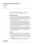
A typical example of the purpose of such a lookup system is described in
figure 1. As you can see the services in the network become available
for the PDA, when it participates in the network itself. You can imagine
that in this example also the television knows how to show the video of the
monitoring camera and the computer is able to switch the lamps.
The concubiNet lookup system is planed to become an example of a “growing service”, which complies with the requirement of adaptation to the available performance. So there exist a minimal lookup, always available, no
matter how small the participating devices are and a centralized, more
powerful lookup can be started, if the necessary performance exists somewhere within the network.
3.3
Resource Control
If you think of the available computing power in a standard PC today you
can imagine that the CPU is idle most of the time. Therefore concubiNet
shall be able to detect imbalances in load of the devices and correct them
by giving the possibility of outsourcing tasks. For example if a big application with high need of memory is started upon a small PDA the device can
free memory by outsourcing parts of the application to a PC.
3
Concept
26
Figure 1: Lookup service
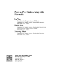
In concubiNet this service is called the loadbalancing service. Like the
lookup it will be a growing service with a minimal system always available
on every concubiNet participant and a more powerful, centralized service
only available, if the necessary performance exists somewhere in the network (see Figure 2).
3
Concept
27
Figure 2: Loadbalancing service
3.4
Surrogates
We know that certainly we are not the first having the idea of a network
having the properties described above. Until today there appeared a lot of
good approaches, e.g. JINI or UPnP, also described in one of the former
sections. So we did not want to develop another “standard”, incompatible
3
Concept
28
with all existing systems but a protocol, which is able to include all the
existing and future technologies.
To achieve this aim and because we know that in one year of the project
group existence we will not be able to implement all of our plans, we will
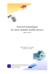
create an interface, over which it will be possible to connect foreign network technologies. How this is planed in detail is described in the section
“Implementation”.
Figure 3: Concept of surrogates and translators
3.5
A “Sea” of Movable Objects
To realize the former described systems, we decided to create some sort
of “sea” of movable objects, which enables us to fulfill all the requirements.
In this section, this concept of a “sea” of movable objects is going to be
illustrated. To understand the idea of the concubiNet one can imagine that
every device which is capable of running CCN-services can be seen as a
basin. This basin, as shown in the following figures, can house a number
of bigger and smaller fish depending on its size. The fish, of course, represents any service or object (e.g. lookup service) running on that device.
It is necessary that these basins can exchange the fish they are housing,
because a fish might get bigger the longer it lives in its environment. That
way it is possible that bigger basins could “help out” smaller basins and every single fish is able to live - no matter which basin he lives in. The water
of all basins combined would be the concubiNet in our imagination. And
there is another important aspect: Because the fish does not care in which
basin he lives in and he is able to swap to another basin, basins can be
integrated into the accumulation of basins as well as being removed from
it freely - the fish can be distributed to the basins - in the future this should
3
Concept
29
be handled automatically. This underlines the capability of mobility in this
concept. As a matter of fact there is no real “sea”; its an accumulation of
basins as described before and the movable objects are the fish.
In order to give the reader a more detailed overview of this whole scenario,
a few figures might be helpful:
As you can see, two basins of different size are joint in this case. The
smaller one runs out of space, because the trout it is housing has grown.
The bigger basin has no space either; it is already housing a carp and a
pike which need all the space.
Fortunately a much bigger basin joins these two basins which is only housing a small salmon.
3
Concept
30
Because the basin running out of space asked for it, the bigger basin takes
the trout and there is enough space for every fish again.
3.6
Communication
After getting to know the basic concept of the concubiNet now the communication between CCN-objects is shown. CCN-objects are special Java
objects used for applications which are based on concubiNet. Communication can be divided into two parts. At first the CCN-object has to find
the desired dialog partner. Regarding to the network scalability there are
different ways of locating or looking up objects. The second part is the
communication itself, meaning the transmission of messages.
3.6.1
Distributed Lookup
In its simplest form, the concubiNet is only build by a group of handhelds.
To convert this into the picture of the sea of objects we only have a number
of basins. When an object wants to speak to another, it tells its basin.
This broadcasts a message, asking the other basins, if anyone knows this
object. That is the basic idea of locating an object working in the spirit of
peer-to-peer networking.
3
Concept
31
A much simpler case is searching for an object which is located within the
own basin. Basically the two objects could then communicate by reference
and there is no need for middleware. But what would happen, if one of
the objects moves to another basin? Then the reference to the local object
would become invalid and a new lookup had to be started. Furthermore the
type of communication would differ. In the situation where the object is local
the standard Java method calls could be used, but if the object is remote
somewhere else the special concubiNet calls had to be used. To avoid this
problem, one CCN-object must not have a Java reference to another. So a
special object is needed which coordinates the communication and creates
the illusion, that a CCN-object can be interacted with directly. This part is
indicated as a square fish.
3
Concept
32
3.6.2
Central Lookup
Although being simple, the disadvantages of the distributed lookup are obvious. When there is a large concubiNet with more than e.g. 50 basins, the
net will soon become unreachable because of the high traffic. Furthermore
small devices with less resources have to spend valuable processing time
every time someone searches for an object. Knowing this, this approach
should be used only if there is no other choice. So the decentralized search
is only used in a small concubiNet with low equipped hardware. Having a
large concubiNet with well equipped PC’s opens new possibilities for the
lookup. One basin is chosen to be a dedicated lookup server which holds
a map of all CCN-object’s in the net. When anybody searches for a CCNobject he only has to ask the server. This directs traffic and processing
expense to a part of the concubiNet which can afford it. But even an well
equipped PC might get problems if it had to store all Wrappers of the concubiNet. Therefore we only store significant information about the CCNobjects in the central lookup and can determine which CCN-objects fit to
a query. Then the communications objects can be retrieved by standard
concubiNet OS features.
In the following pictures our Look Up Service is illustrated as a big fish regarding to its resource needs. As told before it contains information about
the CCN-objects in the net. Because of this it is filled with squared fishes
indicating this information.
3
Concept
33
The Look Up Service gets the search request and identifies the correct
communications object. At this point a semantic lookup function could be
integrated by expanding the request syntax. For example the object could
describe the searched object as: “A big fish which can be found in ponds”.
A clever lookup would understand that a carp is meant.
After having received the communications object, the object can talk to the
other using the communications object.
3
Concept
34
The adjusted picture of our sea of objects would be a collection of basins
which have fish in it. Every fish is within its communications object. When
the fishes want to talk to one another they have to lookup it first and then
receive the desired communication object either by central, distributed or
local lookup. The communication is unmodified for remote or local communication.
4
Technologies
4
4.1
35
Technologies
Introduction
As concubiNet is a two-semester project of twelve students, it is going to
be a complex project as well. We will be confronted with a lot a problems,
some of which may be well known already, some may not. We are not
supposed to develop something which already exists, but something new,
so it is logical and also good convention to make use of existing technologies. We thoroughly examined some technologies which were interesting
for us, and in the following section these technologies and some concepts
will be introduced to the reader, as they form a base platform of our future
development.
4.1.1
Advantages of Re-Using Existing Code
When we started our concubiNet project, the first thing we did was to have
a close look at the state of art and development of existing technologies.
Those overviews of some of the technologies we examined carefully in the
seminar phase at the beginning of our project and can be found in the
introduction of this document. This step was necessary on one hand in
order to put all the project group members on the same level of knowledge
about the relevant topics, and also to find out, which technologies can be
used by us as base technologies, so that we could go on and develop our
network on those existing platforms instead of developing already existing
technologies again by ourselves.
The advantage of re-using already existing code is that you can be relatively
sure that the code works and is tested by a lot of people. This is applicable
in general for all developers, as we want to create something new, and just
re-use already existing, reliable and well known technologies, in our case
for instance JXTA XML-RPC and others.
4.1.2
Perspective “Open Source”
Another topic at the beginning of our project was “open source”. When
we started working out a concept for concubiNet we quickly realized that it
would not be possible to finish the whole project within one year and then
to be able to say: “It’s all done”.
We agreed upon a concept and time schedule which states that we are
going to develop the core system of concubiNet but that there would not be
time enough to go on developing all the modules which are still required for
the network, like drivers, hardware specific modules, translators for different
wireless technologies like Bluetooth, UPNP and others.
As this is a university project and we are not going to sell the completed
part of our work, we agreed upon the idea to develop concubiNet as an
open source project. After our year of work we will be done with our project
group, and there would be no continuing work on the net afterwards in order
to finish the project in all its aspects. As an open source project, everybody
who is interested can join the group of developers and help to finish the
4
Technologies
36
project, even for his own interest, as long as he agrees on the open source
paradigm.
We created a website, www.concubinet.org, that reflects the open source
character of the project, and we hope to find interested developers for it.
However it is not yet stated which open source licence will be used.
4.1.3
Which Technologies are Used in concubiNet?
ConcubiNet was developed with Java 1.4.1 from Sun Microsystems. The
core platform of concubiNet will run on “normal” computers first, these can
be PCs or handhelds or any other device which has enough memory and
resources to run the Java Virtual Machine from the Java Standard Edition
J2SE. More information about Java is given in the next section.
The JXTA Project will be the core platform of our concubiNet development.
A short introduction to JXTA already was given in chapter 2.5 and will be
treated in greater detail in the following section.
XML-RPC is a specification for Remote Procedure Calls using XML. RPC
is a mechanism, that allows software on different machines, which are connected via a network, to call a procedure from one computer, execute the
procedure on another computer and return the result to the initial computer.
Problems using RPC are for instance the network protocol which is used
or the type of parameters which are passed from one to another computer,
which may run different operating systems for instance.
Although RPC is much slower than a normal, local procedure call, it gives
the user the possibility to develop distributed applications. From the programmers point of view, he just calls a normal method and then goes on,
using the returned value. Inside this procedure call, there can be a remote
procedure call, which then takes care of sending the parameters and returning the result after execution. The programmer himself can concentrate
on developing his application.
As there is a complete XML-RPC package available for the Java implementation of JXTA we decided to make use of that package, too, and will
include the RPC mechanism in our project to realize remote procedure calls
wherever necessary. XML is also the generic message format of JXTA so
choosing XML as the marshalling format for RPC was the only logical step.
XML-RPC will be described in detail in the following sections, along with
the other technologies.
4.1.4
Why Java?
Java from Sun Microsystems is a programming language with a very powerful API. Runnable programs can be created very quickly, Java is object
oriented, Java is widely accepted and there are very good free development
environments for it as well. Using Java as our programming language for
concubiNet will take us fewer effort than developing in other languages, as
Java gives us a much more powerful and larger API and packages which
we can use and re-use for our project. concubiNet will not be designed
and optimized for the maximum computing speed of an applications, but
4
Technologies
37
as the running applications will be distributed applications, the effective execution speed will be determined by the speed of the network rather than
the programming language. Thus, Java became our first choice.
Furthermore, we had a discussion which version of Java to use. As we are
developing an ad-hoc network which will also include small devices in the
future, we thought it would be possible to develop our whole project with
the Micro Edition of Java, J2ME. But J2ME gave us so many restrictions
(like the need of Java Reflection to instantiate new classes during runtime)
that we could only chose the Standard Edition as our primary development
platform. In the future there will be attempts to realize a network with small
devices as well, which included devices which cannot run a full J2SE virtual machine. Those devices will probably be connected to concubiNet via
a surrogate, which is a representative for the smaller device, which itself
can be a bigger machine running a full SE virtual machine, and plainly
communicating with the smaller device.
We will start our development with Java 1.4.1, so it will be likely that anybody needs at least this version to be able to run parts of - or the whole concubiNet.
4.2
JXTA, Our Root Technology
For a short introduction to JXTA please see chapter 2.5 in the introduction
of this document. JXTA was one of the technologies we discussed during
the seminar phase and later on we finally decided to use the JXTA project
as our core platform for communication in the concubiNet network.
4.2.1
The Peer-to-Peer Idea
concubiNet is a step into the field of ubiquitous computing. Therefore, JXTA
is ideally fitted for our vision, as it realizes a platform independent way of
creating a peer-to-peer network. The following points are important in such
a network:
• Discover other peers and their services
• Publish its available services
• Exchange data with other peers
• Route messages to other peers
• Query peers for status information
• Group peers into peer groups
JXTA is a set of protocols which realize the given demands. That means,
using the JXTA protocol suite, we will be able to handle all the above given
claims to a peer-to-peer network, without having to implement any of these
core services by ourselves. The JXTA protocol suite consists of six protocols, as shown in the following diagram.
Each fundamental peer-to-peer functionality is represented by its own layer
or protocol in the stack. The Protocols are more or less independent from
4
Technologies
38
Figure 4: The JXTA Protocol Stack
each other; a peer can choose which of those protocols it really needs and
which not. So JXTA is very modular in its concept.
JXTA makes use of so called advertisements. Any kind of resource in the
network which is supposed to be accessed by a peer, whether it is a peer
himself or a service which is served by a peer, is stored in an XML advertisement file in the local cache of a peer. The peer can now spread the
advertisement in the network, or another peer can use a discovery to find
new advertisement on other peers. Rendezvous peers are used to store
all the advertisements of neighboring peers and thus reducing the network
load. This advertisement idea is described later on again in the discovery
protocol.
4
Technologies
39
The JXTA concept not only consists of the six protocols. JXTA can be divided into three layers: JXTA Core, JXTA Services and JXTA Applications.
The core layer provides the basic peer-to-peer functionality to all the peers.
It also includes the six basic protocols as introduced in the above figure and
described later on. Although these protocols are implemented as JXTA services, they are part of the basic core platform and not of the Service layer,
in order to separate the basic functionality from the Service solutions for
applications using JXTA. The Services layer then contains functions which
are not absolutely necessary for a P2P application. Among them are to
search for resources on a different peer, sharing documents on a peer
and to perform peer authentication. As this layer is not part of the JXTA
core, it is mainly being developed by the JXTA open source community as
additions add-ons. The third layer, the application layer, is on top of the
Services layer and constitutes what we know as an application, like instant
messaging or file sharing.
So why now did we choose JXTA for concubiNet? We wanted to have an
independent base platform, and JXTA gives the developer a great freedom
in the choice of technologies. As we were going to program with Java,
we could make use of the Java reference implementation of JXTA we can
make use of the JXTA XML-RPC package and we are open for a lot of future
developments, as JXTA can be extended and all the protocols and layers
used by and in JXTA can be replaced by a developer if wished. In specific
standalone systems JXTA may not be the first choice, as XML messages
mean a great flexibility and are very generic, but they introduce a great
overhead if only needed for limited message types. But JXTA builds the
base of a very profound platform which has a huge open source community
and is in vivid development and support of more and more developers. This
and the generic, flexible, modular approach of JXTA has the outstanding
potential help extending concubiNet with more and more features in the
future.
4.2.2
Advantages of XML
XML is language independent. Any program language being capable of
manipulating text strings can also create, read and modify XML files. XML
is simple to understand, the structure is quite similar to the one in HTML
and correctly formatted XML documents can be viewed in a browser. XML
is self-describing for humans, because it uses metadata tags and attributes,
which describe the enclosed data. XML is more extensible than any other
languages. Any developer can create his own set of markup tags to structure his own data. Last but not least XML is a standard of the World Wide
Web Consortium and is very popular amongst developers.
4.2.3
JXTA Protocols
The following subsection will describe the JXTA protocols more detailed.
As stated above, advertisements are the basic means to exchange information. This means the problem of finding a resource in the network can
be reduced to the problem of finding advertisements describing those resources. The so called Peer Discovery Protocol defines two types of
messages: The Discovery Query Message and the Discovery Response
4
Technologies
40
Message. A peer sending out a Query Message can set the type of advertisement it is looking for, or also other attributes and values which an
advertisement must fulfill that is to be found.
As already said, the six basic protocols, which include the peer discovery
protocol, are implemented in the JXTA core as services. So there is a so
called Discovery Service, which can directly be used by the developer. The
Service interface also gives the possibility to publish a new advertisement
either in the local peer cache or publish it remotely over the network.
The next protocol or JXTA core service is the Peer Resolver Protocol.
The discovery service is built on this service, the resolver service provides
really handles the sending and receiving of messages. It would go into too
great detail to describe the whole protocol here, but it gives the user a more
generic message-handling framework. It is possible to implement own handlers and with them to define your own functionality to a peer group.
The next underlying protocol in the Rendezvous Protocol. The rendezvous
service not only provides a means to propagate messages to other peers
across the network, but also to provide rendezvous peer services to other
peers. That means, with the Rendezvous Protocol, it is possible to broadcast messages to members of a peer group which are outside of a private
network of which the peers within the private network are maybe not aware
of. The Rendezvous Peer can thus act as a cache for advertisements, and
peers can issue discovery messages to the Rendezvous Peer in oder to
find other peers and their advertisements.
The Peer Information Protocol can be used for monitoring a remote peer,
using status information etc. But in its current state of development this
protocol is not very efficient and will not be treated here.
The next important protocol is the Pipe Binding Protocol. Two JXTA peers
communicate with each other after finding the advertisement by opening an
input or output pipe. Before this is possible, a pipe has to be bound to a
peer endpoint. This is established by the Pipe Binding Protocol. The PBP
defines a set of messages that a peer can use to query remote peers to
find an appropriate endpoint for a given Pipe Advertisement and respond
to binding queries from other peers. After a pipe has been bound to an
endpoint, a peer can use it to send or receive messages.
Due to the ad-hoc nature of a P2P network, a message between two endpoints might need to travel through intermediaries. An intermediary might
be used to allowing peers with incompatible network transports to communicate by using the intermediary as a gateway. To determine how a
message should be sent between two endpoints, a mechanism is required
to allow a peer to discover route information. The Endpoint Routing Protocol (ERP) provides peers with a mechanism for determining a route to
an endpoint, allowing the peer to send data to the remote endpoint.
4.3
XML-RPC
ConcubiNet is designed to support communication in heterogeneous networks and it was decided to take JXTA as our root-technology. After that
it was just a small step to fill the gap of remote procedure calls, which occured, with the existing implementation of XML-RPC for JXTA. It seems
4
Technologies
41
to fit well and we started developing our communication around it. This
section should provide the reader a simplified view over XML-RPC and its
binding for JXTA and concubiNet, so that he is able to understand the basics and to make his own decision, whether it is a good idea to use it, or
perhaps it’s not.
4.3.1
XML-RPC spec and the binding for JXTA
Like an open standard as it is, XML-RPC [11] is widely used and hosted
by an open-source community on www.xmlrpc.org. It’s a specification and
a set of implementations that allow software running on disparate operating systems, running in different environments to make procedure calls
over heterogeneous networks. It’s remote procedure calling with XML as
the encoding. XML-RPC is a lightweight XML-based protocol for remote
method invocation over (but not necessarily) HTTP. It emphasizes simplicity and ease of use, enjoys broad support on many platforms and is used
by many freely-available Web Services.
You might think of XML-RPC as SOAP’s little brother where XML-RPC has
far fewer features by comparison. Those features are traded for simplicity
and minimal overhead, allowing the protocol to be fully and easily implemented on even the most modest of devices.
The net.jxta.xmlrpc package provides a transport for XML-RPC over
JXTA pipes allowing the use of RPC-oriented services amongst JXTA peers.
The Protocol XML-RPC is a Remote Procedure Calling protocol that
works over the Internet. An XML-RPC message is an HTTP-POST request. The body of the request is in XML. A procedure executes on the
server and the value it returns is also formatted in XML.
Procedure parameters can be scalars, numbers, strings, dates, etc.; and
can also be complex record and list structures.
The Implementation for JXTA The implementation XML-RPC for JXTA
[12] is pluggable in various ways and offers much flexibility.
Server Features
• pluggable XML-RPC implementations (Apache, Marquee, etc.) via
Jakarta Commons Discovery [13]
• publish via pipe or module advertisement
Client Features
• supporting both asynchronous and synchronous invocation
• pluggable response parser via Jakarta Commons Discovery
• connect to server by both pipe and module advertisement
• separate onResponse and onFault callbacks
4
Technologies
42
4.3.2
How It is Used in concubiNet
XML-RPC is used in concubiNet in the publishing version via Pipe Advertisements, rather than via Module Advertisement. It is the more simple
alternative and the concept of input- and output-pipes is clear to understand. Both the synchronous and the asynchronous version are present
and explained further more in the Implementation Agent section. As any
RPC, our implementation also has two sides, the server and the client.
The Server Side Any CCN-object, which is instantiated in concubiNet,
has to provide its remote methods to other objects. This is done in the
method agent.openService(Wrapper aWrapper), in which the agent registers a new handler in the XML-RPC Server for this specific CCN-object
and opens a new PipeListener, which listens for incoming RPC calls to direct to the server. This PipeListener is stored in a hashmap (required for
later removal, which is done by the method agent.closeService()).
The Client Side If a wrapper, which is switched to remote, wants to call
his CCN-object, it must use the XmlRpcClient.execute() - method, which it
can use after calling the getRpcClient(CCNID id, String name) - method.
This method returns the XmlRpcClient object for the appropriate CCNID,
whose execute() - method could be used in the way it is described in the
implementation agent section.
4.3.3
Conclusions after Working with It
The implementation of the communication with XML-RPC for JXTA is well
formed, with one exception: the caching of XmlRpcClients. Each XmlRpcClient - Object is instantiated with its own ClientContext, which means
a specific peerGroup, a RequestPipe and a ResponsePipe and could be
used for many remote method invocations with the same remote object. Its
instantiation is a high cost operation, that means it lasts up to 3 seconds
to create a new ClientContext, which is far to much and it was considered
to implement a caching mechanism to reduce the effect. The wrapper is
responsible for communication, so it has to store the spezific ClientContext
and use it, if needed.
To make it short, if anything happens to the corresponding CCN-object,
e.g. it is moved to another agent, the ClientContext is broken and RPC call
will fail after a timeout. Our solution is to catch the RPC fails and produce
another ClientContext which ends up in up to 10 seconds waiting for a
remote procedure call which is not satisfying.
The central problem is the XML-RPC implementation for JXTA. It uses parts
of other XML-RPC implementations like apache-xml-rpc and its documentation is horrible. The advantages of using an existing solution ends up
in problems, which only could be solved with much effort. Many options,
the implementation provides, are not used by concubiNet like using simple
parameters in remote method calls. ConcubiNet has its own solution for
calling remote methods with complex parameters as shown paragraph 6.1
on page 47, so this part of XML-RPC is not used.
4
Technologies
43
Possible Solution Now project JXTA has evolved and provides many
more options than its first occurence and XML-RPC for JXTA seems to
be stuck where it was. It should be considered to replace the whole XMLRPC layer with a home-brewed solution in pure JXTA. JXTA provides it own
JXTA-Services concept which could be used to implement RPC with more
control over the source and - with the same priority - over the performance
of the overall system.
5
Architecture
5
5.1
44
Architecture
Conventions
Because of many ways a layer model can be interpreted we have to define an own standard. There are two basic elements used in the following
model. The first one is the alignment. Every block can only communicate
with its horizontal and vertical neighbours. The second type of connection is indicated by colouration. The basic hard- and software of the host
on which the concubiNet software is ought to run is coloured in light gray.
The concubiNet middleware is dark gray and the applications running concubiNet programs or using them are black. Now that the basic semantic of
the layer model is explained we can go ahead by analysing it.
Figure 5: Layer Model of concubiNet
5.2
Analysis
5.2.1
Hardware Layer
There is not much to say in this subsection. The concubiNet middleware
requires a Java Virtual Machine. Because of being a middleware for ubiquitous computing the concubiNet has to be run on PC’s as well as on mobile
computers and PDA’s. So the J2 Micro Edition is a part of the JVM layer in
our model. Unfortunately the KVM [4], a small JVM for limited devices, does
5
Architecture
45
not fulfill the requirements because of missing the foundation for the downloading and execution of dynamic content and services. Therefore we focus
on the part of the J2 Micro Edition called Connected Device Configuration
(CDC). For the current JXTA implementation a TCP/IP stack is needed, but
concubiNet only requires the JXTA interfaces. So if a JXTA implementation
appears not using TCP/IP, concubiNet does not need TCP/IP.
5.2.2
Middleware - concubiNet - and Application Layer
The basis of the concubiNet is built of the so called agents. All the communication between devices is bundled over the agents, and agents themselves use the JXTA protocol [6] for communication. In the picture of our
"sea" of movable objects the agents take the place of the basins. Every
hardware device which wants to play an active role in the concubiNet has
to run an agent.
Certainly the LUS (Lookup service) needs to talk to all agents. How else
could it be able to find the CCN-objects distributed on the different agents?
The LBS (Loadbalancing service) needs to talk to the agent too, because
it has to be able to talk to other LBSes on other devices and - like all communication between devices - also these are bundled over the agent.
Wrappers are in connection with the agents, e.g. when on one machine
there is a Wrapper for a CCN-object running on another machine, again the
communication is bundled over the agent. Not necessary to explain, that
a Wrapper has connection to a CCN-object. The Wrapper is surrounding
the CCN-object indicating that the communication with another CCN-object
is only possible by accessing it by its Wrapper. The Wrapper can also be
found in our "sea" of movable objects as the squared fish surrounding the
real fish and acting as the communications object.
As you can see, the first vague idea of a "sea" of movable objects with fish
swimming in basins is still represented in our layer model.
One could ask now, why the CCN-object is coloured black and thus associated with the application layer. The reason is that the application developer
certainly has to implement his own CCN-objects. In contrast to that the
wrappers for the CCN-objects are exactly defined - in the future they shall
be created automatically by a software tool.
The highest layer is the application layer. A concubinet application consists
of a number of CCN-objects.
6
6
Implementation
46
Implementation
The basic concubiNet sytem was designed to consist of four central components, and we decided to stick to this structure in our implementation
step, so that now concubiNet comprises of the following four packages:
• org.concubinet.agent
• org.concubinet.ccnobject
• org.concubinet.lus
• org.concubinet.lbs
The agent-package contains the classes that are necessary to start concubiNet and the JXTA-Platform on a single host. Here you can find the
class Agent, the core object of concubiNet, that manages all applications
running on this host and provides basic communication facilities, i. e. it
is able to generate requests in the JXTA protocol language and manages
inter-object-communication of CCN-objects on different machines.
As subpackages it contains org.concubinet.agent.agentgui – the user
interface to provide information about this agent and to invoke actions on it
– as well as org.concubinet.agent.classrepository – a storage for Java
classfiles, that are transferred to the local host on demand during runtime.
The ccnobject-package contains the class CCNObject – the basic class for
a concubiNet application object, that provides mechanism to make a CCNobject movable in the system and let it cope with threads and events. The
class Wrapper is needed for maintaining the corresponding CCN-object’s
lifecycle and for communication purposes. The class CCNID provides the
unique identification number that each CCN-object needs.
The lus-package has the responsibility for both local and remote search for
other CCN-objects with certain characteristics. The remote search is once
more divided in decentralized search (a search without a LookUpService
running) and central search, when an instance of LookUpService is running
in this concubiNet. The package also contains the class SearchTree, which
is our data structure used to represent the class hierarchy. Every CCNobject has an equivalent leaf of type ObjectInfo in the SearchTree. The
query language of our search mechanism is realized by a Query-object,
whose member data and properties can be set to specify a search request.
The lbs-package finally provides concubiNet with a load balancing service to avoid unbalances of load. Every Agent has to track its own load by
means of a LocalLBS-object, that stores which resources each CCN-object
claims and utilizes in a special ResourceDistributionMap-object. For this
purpose every CCN-object has a member of type
ResourceDescription. In concubiNet-systems of a certain size there should
exist a CentralLBS on an adequate host somewhere in the system. This
instance maps the load of the entire system to a LoadMap-object by communicating with all local LBS instances. Implementation details are illustrated
in the following subsections.
6
Implementation
6.1
47
Agent
The Agent is the container class on every host (or peer) participating in
concubiNet. It implements the singleton design pattern, so that only one
unique instance can be running on a VM. Therefore instead of a constructor the method getInstance() should be used. Its primary function is to
manage all CCNObjects and Wrappers needed on the local machine.
An Agent is the first thing to be started on a participating host, because it
contains the main routine which
• instantiates a local SearchTree,
• configures the local agent by reading in the configuration file and using AgentConfigurator-Hotconfiguration to start objects
• initiates the local ClassRepository
• starts the JXTA-Framework including creating the concubiNetPeergroup
• opens an input pipe and installs a listener on it, that’s waiting for incoming messages
• tries to find a central LUS via distributed searching and sends its local
SearchTree to this LUS if existing.
The Agent provides basic communication facilities, i. e. it is able to generate requests in the JXTA protocol language and manages inter-objectcommunication of CCN-objects on different machines. For that purpose it
assigns every newly created CCN-object a unique CCNID and opens an
input pipe for its Wrapper in the method openService(org.concubinet.ccnobject.Wrapper wrapper). Similarly an input pipe is opened for every
Wrapper that comes to the local host only for communication purposes or
after an object transfer using the method registerWrapper(org.concubinet.ccnobject.Wrapper wrapper). All locally open pipes are stored in the
HashMap openPipes and all local Wrappers are stored in the WrapperList
localWrapperList. When a CCN-object and its Wrapper are removed
from the local host, the method deregisterWrapper(org.concubinet.ccnobject.CCNID objectId) closes the pipe and removes the Wrapper from
the wrapperlist.
The Agent offers the getRpcClient(org.concubinet.ccnobject.CCNID
agentId, java.lang.String agentName) method to itself and its Wrappers, that returns an XML-Rpcclient. With this client’s methods execute
and executeAsync the calling object is able to establish a communication
to another open input pipe of any CCN-object, i.e. a remote call to a method
of the remote object is executed.
Transfer of CCN-objects to a remote Agent is also done via XML-Rpc.
The transfer is initiated by the method transferObject(java.lang.String
objectId, java.lang.String agentId). Because of the restricted number of datatypes that can be transferred via XML-Rpc, the object has to be
serialized first. With this bytecode as a parameter a remote call to takeObject(java.lang.String objectId, java.lang.String wrapperClassname,
byte[] serializedObject, java.lang.String remoteClassrepositoryId) is executed. Also the CCNID, the name of the wrapperclass and the
6
Implementation
48
PipeID of the local classrepository are needed as parameters, so that the
object can be correctly reinstantiated on the remote host and, if the necessary classcode is not available there, the local classrepository can be
asked to transfer the classcode, too. For a more detailed description see
6.1.3.
Furthermore the Agent invokes the search routines used to locate CCNobjectwith certain characteristics. The entry point for any search is the
method searchInfo(org.concubinet.lus.Query). Depending on the values for locality and quantity of the search (as indicated in the parameter of
type Query) and also depending on the existence of a central LUS, one of
the three different modes of search
searchInCentralLUS(org.concubinet.lus.Query),
searchLocal(org.concubinet.lus.Query) or
searchDistributed(org.concubinet.lus.Query) is invoked.
6.1.1
Configuration
The interpretation of the configfile is done in the start()-method of the
org.concubinet.agent.AgentConfigurator. Execution of this method is
the only function this class achieves. The AgentConfigurator provides access to member attributes representing the values from the configfile, they
are updated during a run of start(). The XML-parsing itself is done by the
DOM Parser contained in the J2SDK 1.4.
Implementation of HotConfiguration Realization is really simple: In
the method configureAgent() within the Agent class a java.util.Timer
is set up. This timer periodically executes the ConfigTimerTask.run()method which checks the date of the last change of the file. If a change is
detected, it restarts the configuration by calling the start()-method in the
AgentConfigurator.
6.1.2
Joining concubiNet
To participate in concubiNet, the Agent has to join the concubiNet JXTApeergroup. This is done within the Agent.startJxta() - method, which is
called while initiating the Agent.
The concubiNet-PeergroupID The concubiNet-PeergroupID is a hardcoded String: jxta:uuid-800E4B263E154E1EB844BF7C0807287B02, that
is because we want to make sure, that it is always the same. The method
getPeerGroupID() takes this string and generates the Java-object PeerGroupID, which is used to locate our peergroup concubiNet. The method
startJxta() does nothing else than setting the global JXTANetPeerGroup,
whose Discovery-Service is used to locate our concubiNet-Peergroup. Then
it calles the central method joinConcubiNet().
Searching for concubiNet The first thing to do now, is searching for an
existing concubiNet-Peergroup. If the group is found, this Agent is able
to join in. In this implementation, sometimes no concubiNet-Peergroup is
found, although there is one. That seems to be a problem, but because
6
Implementation
49
we have a hardcoded PeergroupID, any newly created joinConcubiNet()
joins implicit the existing one. Deletion of this searching part leads to a
speedup at starting time.
Creating a new Peergroup If no existing concubiNet-Peergroup could be
found, a new one is created with the same PeergroupID. It is named concubiNet and gets the description ConcubiNet – an operating system for
ubiquitous computing. Then the Peergroup-Advertisement is published
in the global NetPeerGroup for other peers to find.
What is left to Do Now the Agent has joined the concubiNet-Peergroup
and is able to participate in. It only has to open an InputPipe for other
agents to communicate with it, which is done in openAgentInputPipe().
The next step to do is to register any CCN-object, that is waiting for registration.
6.1.3
Transfer of CCN-objects
The transfer is nothing more than an XML-RPC of a method, that takes
the serialized object in form of a bytearray by its parameters. The called
method is Agent.takeObject(...). On the receiver side this method works
as follows:
1. A classloader (repository) is created, that searches for classdefinitions in the own repository and in the originator’s repository. For details see page 6.1.4.
2. Search for an already existing, empty wrapper for the transferred
CCN-object by its CCNID. If no existing Wrapper is available, it has
to be created. To find the matching class, the former created classloader is used. The fully qualified classname of the wrapper is passed
to takeObject by parameter.
3. Now the serialized object has to be implanted into the Wrapper. This
is done by the method Wrapper.wakeUp(byte[] serializedObject,
ClassRepository cr). The classrepository has to be passed so that
missing classes can be loaded during the deserialization by using the
correct classloader.
4. At last the pipe to the CCN-object has to be opened again so that the
CCN-object is available in the network.
If everything succeeded the method returns true to tell the originator
that the transfer is complete.
The method calling takeObject(...) is transferObject(...) on the
originator’s site. It does the following:
1. Get an RPC-Client for the remote Agent by which the takeObject(...)
can be called
2. Pack the CCN-object. Therefore the CCN-object’s pipe is closed so
that no more method-calls can be done, the CCN-object is sent to
sleep (see CCNObject.goSleep()) and serialized.
6
Implementation
50
3. The last step is the remotecall of takeObject(. . . ).
Several failure handlings follow. These are necessary to guarantee,
that the CCN-object cannot be lost. Either the CCN-object is transferred successfully and the local wrapper remains empty or the transfer fails (perhaps because the remote Agent is no longer available)
and the CCN-object remains on the originator.
6.1.4
Classloader Concept
We faced the following problem: Imagine a CCN-object has to be transferred to an Agent that does not know the corresponding classdefinitions
(Java bytecodes) yet. In this case it is not possible to deserialize the object. So we had to find a way to get the correct bytecodes, load them on
the recipient’s VM and use them during deserialization.
Possibly the easiest way to find the correct bytecodes is to ask the originator, because if he has the object he obviously must have the bytecodes
too. To get the classes from the originator we created the classrepository.
The classrepository performs two tasks: On the one hand it is a common
classloader, on the other hand it is able to deliver the bytecodes of the
classes.
On an Agent we have a so called ClassRepositoryFactory (classname is
org.concubinet.agent.classrepository.ClassRepFactory), serving two
methods:
1. ClassRepository getLocalClassRepository() - Returns a classloader, that searches for classdefinitions only on the local machine
2. ClassRepository getClassRepository(CCNID) - Returns a classloader, that searches for classdefinitions on the local machine and
further on it is able to ask a remote classrepository for bytecodes,
running as a JXTA service and defined by the passed CCNID
To enable the second mechanism, every Agent has to announce its local
ClassRepository as an XML-RPC-enabled JXTA service. This is done during the first call of getLocalClassRepository().
The process of bytecode-transfer can be described as follows:
1. The originator of a CCN-object passes the recipient the CCNID of his
local classrepository
2. The recipient asks his ClassRepFactory for the matching classloader
3. The deserialization method (Wrapper.wakeUp(byte[] serObj, ClassLoader cl)) uses the classloader just created by using an inheritor of
the java.io.ObjectInputStream: ObjectInputStreamForContext (in
package org.concubinet.agent.classrepository). In this class
the protected method resolveClass() was overwritten so that it now
uses our classrepository instead of the system classloader. By this
technique inner classes and unknown parameter types are detected
and loaded from the remote classrepository as well.
6
Implementation
51
Abstract Factory Design Pattern The classrepository implements the
Abstract Factory design pattern. The abstract factory is the class org.concubinet.agent.classrepository.ClassRepFactory, the abstract product is org.concubinet.agent.classrepository.ClassRepository.
The concrete factory we implemented is org.concubinet.agent.classrepository.FileClassRepFactory, the corresponding produced object is
org.concubinet.agent.classrepository.FileClassRepository.
FileClassRepository First of all the FileClassRepository is a classloader
and therefore has to implement the method Class findClass(String),
that is used by the classloader delegate concept of the Java 2 Platform.
The method will be called by the inherited method loadClass(String)
and encapsulates the local and remote search for classdefinitions by using the method getBytecodeArray(String classname), that delivers the
Java bytecode of the class defined by the parameter.
Method getBytecodeArray(String classname) in detail does the following:
1. First it search for the bytecode in the local repository by calling getBytecodeInputStream(String classname). If this method succeeds,
a bytearray (byte[]) is created and returned.
2. If the method throws a BytecodeNotAvailableException, it is tried
to search for the bytecode on a remote repository if it is set (This is
only takes place if the current FileClassRepository was created by a
call of ClassRepFactory.getClassRepository(CCNID remoteRep)).
3. First step in remote search is to ask the remote repository, if there
is a JAR available containing the class. This is made because the
propability is high, that other classes, also contained in the JAR, will
be needed in the near future and will then already be on the local
machine.
4. If a JAR is available, it is transferred by the RPC of getJarByteArray(String classname) and stored in the local repository. Last step
is to get the bytecode out of the JAR and return it. If no JAR is available, the bytecode of the class is transferred by the RPC of getBytecodeArray(String classname), stored in the local repository and returned.
6.1.5
Finding or Creating Advertisements
When an advertisement corresponding to a well known ID is to be found
or a totally new Advertisement is to be created, the method getPipeAdv is
called.
First of all, when searching for an existing advertisement, the local cache
is checked for this advertisement. If this is unsuccessful, the remote advertisements are fetched with the method org.jxta.discovery.DiscoveryService.getRemoteAdvertisements(...). This is done for a maximum of
three times. If nothing is found a new advertisement with the given ID is
generated.
6
Implementation
52
To generate a new advertisement the method net.jxta.document.AdvertisementFactory.newAdvertisement(...) is used. To get a totally new
PipeId the method net.jxta.id.IDFactory.newPipeID(...) is used. Afterwards this new advertisement is published locally by calling org.jxta.discovery.DiscoveryService.publish().
6.1.6
Finding Neighbouring Agents in the concubiNet Peer Group
With the method getNeighbourAgentIDs() the Agent is able to get a java.lang.Vector containing the agentIDs and corresponding names of
agents in the neighbourhood.
After fetching all remote advertisements with the tag “Name” set to “Agent”
all these advertisements are read in and they are contacted via XML-Rpc
to send their agent name. After the response the ID and Name are put into
the result vector.
When implementing another communication protocoll, that provides a ping
mechanism, this method should be refactored so that a ping is issued to
each agent. Also this method should execute an asynchronous (parallel)
call to the neighbour agents, provided that a more complex return value
is supported, that can contain the id as well as the agent’s name. When
implementing a proprietary protocol this return value could be an XMLadvertisement containing an “ID” and a “Name” tag.
6.1.7
Registration/Deregistration
In order to integrate a CCN-object into concubiNet, you have to register
it after the instantiation. This registration is done by the method registerWrapper(Wrapper aWrapper). You simply provide the newly created
Wrapper and everything is handled for you, such as:
• adding the Wrapper to the local WrapperList
• calling the method openService() and thus handle all JXTA-related
work
• inserting the ObjectInfo of the Wrapper to the local SearchTree
This registration-method is also called when a Wrapper is reinstantiated.
The counterpart of this method is deregisterWrapper(CCNID aCCNID). It
handles everything, that cleanly removes a CCN-object from the concubiNet:
• close the JXTA-pipe of the CCN-objectby calling closeService()
• remove the Wrapper from the local WrapperList
• remove the ObjectInfo from the local SearchTree
6.1.8
Communication
Communication in concubiNet is handled by the Wrappers. They take care
of the differentiation between local and remote calls. Thus if you want to
communicate with another CCN-object you have to get the Wrapper first.
This is done by calling getWrapper(CCNID aCCNID). This method tries to
get a Wrapper of the CCN-object specified by aCCNID.
6
Implementation
53
In detail this works as follows: If the Wrapper is in the local WrapperList it
directly returned. This is the case if
• the CCN-object is located on the same Agent
• the CCN-object was located on the same Agent and has been moved
• a Wrapper has already been fetched for remote communication
If the Wrapper is not available locally the Agent tries to get its classname by
calling getClassName() via XmlRpc. With this classname the Agent tries
to create a new instance of the Wrapper from the local “ClassRepository”.
If this doesn’t work (Bytecode of the Wrapper is not available locally) another XmlRpc-Call to getWrapperClass() is carried out. This call returns
the bytecode of the Wrapper, which is than added to the local “ClassRepository”. Thus a new instance can be created and returned.
After a new Wrapper is created it is finally added to the local WrapperList.
6.1.9
LUS-Integration
When a search request is issued with the parameter “LOCALITY_GLOBAL”
a distributed search is executed. This is done by calling the method
searchDistributed(). This method works as follows: First a local search
is carried out to prevent overhead by calling your own Agent with a XmlRpcCall. If there are not enough search hits corresponding to the quantity in the
Query, the “real” distributed search operation is executed by calling method
collectDistributedObjectInfos(Query):
First of all a Listener is created, that will listen to the responses to the requests sent out. After that all Advertisements that represent Agents are
collected and stored in an enumeration for further processing. This enumeration is now processed one by one and an asynchronuous XmlRpcCall to receiveSearchRequest() is sent to every reachable Agent. For
these XmlRpc-Calls the Query is provided as parameter and the Listener
is added as well, so that the responses can be passed to it.
After sending out the requests a short period of waiting time has to be considered. To minimize this idle time two additional mechanism were added
to the waiting loop. One of them is monitoring the number of responses
received. They are compared to the requests that were really sent out.
If they are equal waiting is finished as every contacted Agent has sent a
response.
The other condition is the monitoring of the number of results. If this number matches the quantity provided in the Query, additional waiting becomes
weary as well. When the waiting loop is exited the results are fetched from
the Listener and passed to the calling method.
receiveSearchRequest() is the counterpart of searchDistributed() that
is called via XmlRpc only. Thus its parameters and return values are byte
arrays. This method simply carries out a local search with the Query provided as parameter. As the parameter is coded in a byte array it has to be
decoded first. Same applies to the result, which has to be coded into a byte
array before getting returned.
6
Implementation
54
6.1.10
Starting a Central LUS
When concubiNet grows, a Central LUS could be required. This is because
the search duration for a distributed search increases with every new Agent
which joins the net.
In the current implementation the Central LUS is started by pressing the
’start a central LUS’ button in the AgentGUI. An automatic start of the Central LUS would be nicer. To implement this, two ways are thinkable.
A counter in every Agent (e.g. queryCounter) could be used to count the
distributed searches. When a threshold is reached, a Central LUS could be
started. This assures that the Agent which creates most of the distributed
searches contains the Central LUS. This could speed up the search duration. With the intergration of the LBS another method could be thinkable.
The LBS starts a Central LUS if it knows a machine with enough capacity
or bandwidth to hold a Central LUS. So here the most powerful machine
would contain the Central LUS. This could speed up the search duration,
too.
When a Central LUS is started on the local Agent the method announceCentralLUSAtLocalAgent is called. With this method all Agents in the
neighbourhood are informed that there is a new Central LUS via XML-RPC
calls to announceCentralLUS().
In general it works the same way as with the distributed search. First all
Agents are searched and stored along with their IDs. With these IDs synchronous XML-RPC calls are carried out to announceCentralLUS() on the
remote side. The results are decoded from byte array to SearchTree and
then passed to the Central LUS for integration.
The counterpart announceCentralLUS() takes care of the steps necessary
to use the Central LUS:
• replace LUS on the local machine if existing
• create a Wrapper for the new Central LUS
• return the local SearchTree
6.2
CCN-object
In this section some special details of the implementation regarding the
package org.concubinet.ccnobject are discussed. Details which are interesting for application developers are described within the developer’s
manual.
6.2.1
Remote Communication
As shown before, remote communication in the concubiNet is basically
done via XML-RPC. This means, that a RPCClient for a special CCNID has
to be created and then a Wrapper can use the method execute(...) to
start a remote call. The details of when to use the client and which parameters are needed is described in the developer’s manual. This section will
concentrate on the RPCClient itself. Basically the RPCClient for a desired
communications partner can be retrieved by using the method Agent.getInstance().getRpcClient(ccnID, "CCNObject"). This creates a new
6
Implementation
55
client which points at the object with the given CCNID. The performance
problem here is that creating a RPCClient takes several seconds. The easiest way to overcome this is to simply cache the RPCClient and only retrieve
it once. In a static network this would be a good solution. But because of
the main feature of moving applications and the basic concept of a scalable network the RPCClient is not valid forever due to the changes in the
net. So we have to cache the client but also make sure that we got an
appropriate one for the current situation in our concubiNet Ṡo the method
getRPCClient() is put into the Wrapper class. In order to determine if a
RPCClient is valid a standard ping() method is put into the Wrapper as
well. So this method uses caching and client validation along with exception handling in order to return a valid client. The design and exception
handling itself was based on practical experience and may be altered if
new experiences are made when extending concubiNet .
6.2.2
Wrapper and Serialization
The basic idea of transferring complex objects via XML-RPC is to serialize them on the origin side and deserialize them on the receiving side.
The details of this in dependency to the whole CCN-object design can
be found in the developer’s manual. When serializing one object recursively every member variable of the object is serialized. Let’s now think
of an application which wants to talk to others permanently and therefore
stores Wrappers as member variables. When this application is transferred
to another Agent all Wrappers are serialized and deserialized. Basically
this is possible but unwise for the concubiNet because the instance for
controlling communication and storing Wrappers within the concubiNet is
the Agent. When using the procedure described the Agent would not be
aware that new Wrappers are on the machine. When another application wants to talk to this application now a new Wrapper would be unnecessarily retrieved. As a result two complete and identical Wrapper
objects would be stored on the Agent which basically is wasting performance, espacially because the number of identical Wrappers would rise
with more and bigger applications. To overcome this problem we simply
overwrite the standard Java methods for serialization. The basic idea is
to involve the receiving Agent into the process of deserialization and retrieve the ’real’ Wrapper via the standard method. Therefore we overwrite
the method writeReplace() in the Wrapper which allows us to write an
instance of org.concubinet.ccnobject.WrapperSubstitute into the serialization stream. This substitute basically stores the CCNID of the Wrapper and overwrites the method readResolve() which is called at deserialization on the recieving Agent. Within readResolve() we only need to
call Agent.getInstance().getWrapper(id) to retrieve the correct Wrapper and thereby involve the Agent and finally overcome our main problem.
Because all used methods are basic serialization methods which are called
every time a Wrapper is serialized we assure that even when the Wrapper
is used as a parameter of a method the mechanism shown above prevents
a transfer without the Agent noticing it.
6
Implementation
6.3
56
LUS
In this section the LUS (Look Up Service) package and the Central LUS
will be introduced in detail. The Central LUS is a high level service of
the concubiNet, which builds on the basic lookup methods and features
of the Agent and the so called SearchTree. Thus at first the basic search
functionality will be described more elaborately before the Central LUS is
introduced afterwards.
The search mechanism is very important in the concubiNet as every communication with another CCN-object means that this CCN-object has to be
found in advance. Therefore, every Agent holds a data structure called
SearchTree, which is a special tree data structure (org.concubinet.lus.SearchTree). In this SearchTree, all information about locally existing CCNobjects is stored on that Agent. This information is arranged in so-called
ObjectInfo objects (org.concubinet.lus.ObjectInfo). Each of them represents exactly one CCN-object and contains information about this object like the CCNID, the Java classname that it is derived from and some
more attributes. In the following figure an example SearchTree is shown:
The structure of the SearchTree is formed similar to the Java class hier-
Figure 6: The Search Tree Data Structure
6
Implementation
57
archy. The ellipses represent so-called ClassNodes (org.concubinet.lus.ClassNode), and the rectangles the ObjectInfos. The root node of the
tree is the CCN-object, which is of the class org.concubinet.ccnobject.CCNObject. Every direct child in the tree which is a ClassNode object (ellipse) represents a direct subclass of the root class, thus a CCN-object. By
traversing the tree one can directly map the nodes to the corresponding
Java classes. This makes it possible to find objects of certain classes or
subclasses more efficiently in the tree. For instance, if a developer wants
to find objects of a class TwoStateObject which might have been defined
in his application, then a search will return all objects which are in the subtree below the ClassNode which exactly represents that TwoStateObject
class. All CCN-objects belong to exactly one Java class which is an implementation of org.concubinet.ccnobject.CCNObject class or derived
from it. The ObjectInfos represent exactly one CCN-object, they are shown
in the figure as squares. This means that an ObjectInfo in the SearchTree
represents an instance of a class of which it is a direct child in the tree.
The mechanism to submit a search to the SearchTree in an Agent is provided by the Query object (org.concubinet.lus.Query). This Query object has to be instantiated and passed over to the SearchTree with the
desired search options set. The search function will then return a set of
ObjectInfos which represents the corresponding CCN-objects.
There are different search modes in the concubiNet. The local search,
the distributed search, and the central search with the help of the Central LUS. The local search just operates as follows: a new Query object
is instantiated with the desired search options set and the Agent calls its
searchLocal(Query) method, which then searches for the ObjectInfos in
the Agent’s local SearchTree. If a global search should be issued and no
Central LUS exists in the concubiNet, then a distributed search will be conducted by the Agent’s searchDistributed(Query) method, which tries to
find ObjectInfos in all neighboring Agents.
The last option makes use of the Central LUS. This additional service can
be started as a CCN-object instance in the concubiNet. It collects all local
SearchTrees of the Agents and builds one big SearchTree. All Agents can
then direct their search requests to the Central LUS which can respond
almost as quickly as a local search. All the corresponding classes of the
search mechanisms will be described in the following in more detail on
implementation level. For the LUS integration in the Agent class see 6.1.9
on page 53.
6.3.1
Query
The basic class needed for a concubiNet look up is the Query class. It
defines several search options:
• locality: Where to search for the CCN-objects – only on
the local Agent (LOCALITY_LOCAL) or in the global concubiNet
(LOCALITY_GLOBAL).
• className: The classname of the CCN-object(s) to find. It is useful
to set this attribute to speed up the SearchTree operation.
6
Implementation
58
• interfaceNameList: The classname of an interface the CCN-object(s)
are implementing. This option currently has no effect.
• objectQuantity: Specifies how many CCN-objects should be found.
If all CCN-object shall be returned this attribute can be set to QUANTITY_ALL.
• attributes: Can be set to search for attributes which are defined in
the CCN-object. attributes is an instance of java.util.Properties.
The search options can be set by calling the constructor of the Query class
and by the given getter or setter methods. Additional to the search options
above the Query class has two more attributes. First a unique queryID
is given to every Query. The second attribute is workingObjectQuantity,
which is an int and is used to manage the number of found CCN-objects
if a limited objectQuantity is given. This attribute can be accessed by the
methods decreaseWorkingObjectQuantity(int count), getWorkingObjectQuantity() and resetWorkingObjectQuantity().
6.3.2
SearchTree
The general structure of the SearchTree data structure and the components
(ClassNode, ObjectInfo) were already introduced by now. Every Agent
holds exactly one local SearchTree. This tree keeps track of the information, which CCN-objects are presently and locally on the same Java Virtual
Machine as that Agent. The means to represent the CCN-objects are the
ObjectInfos. They are stored in the SearchTree and can be accessed with
search-, add-, update- and delete-methods.
The SearchTree not only consists of the ObjectInfos, but also of ClassNodes.
The ClassNodes form the nodes in the tree, while the ObjectInfos form the
leafs. The root node of the tree is (usually) set to the concubiNet class
org.concubinet.ccnobject.CCNObject. As the tree represents the Java
inheritance hierarchy of classes, every child node of the root (or of other
nodes) stands for a subclass of that node or class. The tree can be traversed from the root down to an ObjectInfo leaf for instance, giving the
hierarchy from the base class to the last subclass. This means that every
ObjectInfo is seated under a ClassNode, which also stands for its own and
the ObjectInfos class. In this way it is very easy to find a certain ObjectInfo
if you know the Java class of it.
Having a closer look into the SearchTree class now, it can be seen that
there are the following member variables:
• ClassNode root: It holds the root ClassNode of the SearchTree.
• Class rootClass: It holds the Class of the root node.
• AttributeList attributeList: This is the AttributeList which can
additionally help searching more efficiently in the SearchTree (just a
template, not implemented).
• long numberOfLeafs: The number of leafs (ObjectInfos) in the SearchTree. This is equal to the number of CCN-objects which are locally
present on the same Java VM than this agent and its SearchTree.
6
Implementation
59
• int numberOfNodes: The number of nodes (ClassNodes) in the whole
SearchTree.
There are two constructors. The SearchTree() constructor with no parameters constructs an empty SearchTree with org.concubinet.ccnobject.CCNObject as its root class and node. The other constructor can take a
String name for a different root class, if needed for some reason.
The method wakeUp() is necessary for being able to transfer the SearchTree
to remote Agents and after being transferred this method has to be called.
The reason for this is that attributes which are not transferred with the Object have to be reinitialized. In this class the Logger log is created new at
the destination agent. getSize() is a small method which just returns the
number of ObjectInfos in the tree.
The next paragraph describes the methods in the SearchTree. These are
basically the methods for updating, adding and removing ObjectInfos in or
to the tree.
• UpdateObjectInfo(ObjectInfo newObjectInfo): It takes an ObjectInfo as parameter which carries the new attributes. The ObjectInfo in
the tree which fits to that ObjectInfo parameter (same class name and
CCNID) will be updated in the the tree.
• UpdateObjectInfo(CCNIDccnID, Properties prop): This method
only compares the CCNID of the ObjectInfo in the SearchTree and
updates that ObjectInfo with the new Parameter list as attributes.
• insertNewObject(CCN-objectccnObject): It creates a new ObjectInfo corresponding to that CCN-object and inserts it into the tree.
• insertNewObject(Wrapperwrapper): It creates a new ObjectInfo
which corresponds to the CCN-object that this Wrapper is built for.
• insertNewObject(ObjectInfo objectInfo): This method inserts
the ObjectInfo parameter object into the SearchTree. Therefore it
checks the class that this ObjectInfo represents (for its CCN-object)
and then climbs down the SearchTree from the root node to the
correct position in the Java class hierarchy, maybe creating missing
ClassNodes.
• deleteObjectInfo(CCNID): It searches the whole tree for the fitting
CCNID. When found it deletes the ObjectInfo.
• deleteObjectInfo(ObjectInfo objectInfo): This method also
deletes the ObjectInfo according to the correct CCNID given in the
parameter object.
• private findParentNodeOfObjectInfo(CCNID): This method is used
internally in the above given methods. It returns a ClassNode object
which is the parent node of the ClassNode of which the ObjectInfo
with the given CCNID is a direct child.
• findObjectInfo(CCNIDccnID): This is a private method so far. Internally other methods need the possibility to search for an ObjectInfo in
the SearchTree just by its given CCNID and not by the class name.
As the SearchTree structure does not directly support such a search
6
Implementation
60
this methods needs to traverse the whole SearchTree until it finds the
ObjectInfo with this CCNID.
• searchInTree(Query query): It searches the tree for matches with
the given Query and returns an array of ObjectInfos.
• searchInTreeVector(Query query): The same as above but the return value is a Vector with ObjectInfos. For using the efficient tree
structure of the SearchTree, it is necessary to give a classname of
a CCN-object to find in a Query. First the inheritence path from this
class up to the CCNObject class is created and afterwards the tree
can be climbed down to the ClassNode representing the class of the
CCN-object to find. Here only this subtree has to be searched instead
of the whole tree.
• searchInTreeRemoveInitiator(Query query, CCNID initiatorCCNID): It has the same functionality as the method above, but removes the given CCNID from the results. So a calling CCN-object is
able to remove itself from the returned results.
• private searchInSubTree(Query query, ClassNode node): This
private method is used by the search-methods to recursively search
a subtree with the given Query.
• private searchInSingleNode(Query query, ClassNode node):
This also private method is used by the method above to search for
matches of a Query in the given ClassNode.
• private getInheritencePath(String className): Substantial for
using the efficient tree structure of the SearchTree is this private
method. If a classname is given in a Query, it is only needed to search
the relevant subtree. To find the root ClassNode of this subtree, first
the inheritence path for the classname which is given in a Query up
to the CCNObject-class is created here.
• private mergeVectors(Vector vector1, Vector vector2):
A small private method which is used to merge two Vector objects.
• insertTree(SearchTree insertTree): This Method inserts another
SearchTree and is used for collecting the local SearchTrees of the
Agents when starting a Central LUS.
• private insertPartialTree(ClassNode currentNode,
ClassNode partialTree): The private helper method for the
method above. It recursively inserts a partial tree represented by the
ClassNode object into the current SearchTree starting from the given
ClassNode.
• private getClassNode(String className): This private method
returns the ClassNode object fot the given classname.
Many of the methods mentioned are able to throw Exceptions, more specific LUSExceptions, if an error occurs. The type of error can be even more
specific if exception-classes are used which inherit from LUSException as
InvalidClassnameException.
6
Implementation
61
6.3.3
ClassNode
This Class represents an inner Node (or root Node) of the
SearchTree.
Every ClassNode represents a Java class and
stores the name (nodeName) of the corresponding Java class (e.g.
org.concubinet.ccnobject.CCNObject).
There are two lists inside
a ClassNode. First the list containing child ClassNodes (children),
which are ClassNodes representing inherited Java classes. The second
list contains ObjectInfo objects associated with the current ClassNode
(leafs).
Along with standard getter and setter methods the Classnode class contains methods for accessing the children or leaf objects. For accessing the
children ClassNode objects, the following methods can be used:
• addChild(ClassNode aChild)
• getChild(String name)
• removeChild(String nodeName)
• removeChild(ClassNode specialChild)
getChildren() returns an array of all ClassNode objects. There are more
detailed methods for accessing Leafs. For adding Leafs
• addLeaf(ObjectInfo aLeaf)
• addLeaf(ObjectInfo aLeaf, boolean obeyTimestampWhenUpdating)
can be used. The timestamp-check is needed in case an ObjectInfo shall
be stored but an ObjectInfo with the same CCNID is already present. The
timestamp is used to determine which ObjectInfo is newer and the ObjectInfo with the newer timestamp is kept. The same situation can ocurr while
updating an ObjectInfo. The methods for updating are
• updateLeaf(ObjectInfo newObjectInfo)
• updateLeaf(ObjectInfo newObjectInfo, boolean obeyTimestamp).
An array of all leafs is returned by getAllLeafs(). Depending on the given
properties only appropiate ObjectInfos are returned by the methods either
as a Vector or as an Array:
• getLeafsVector(Properties properties)
• getLeafsVector(Properties properties, int maxNumberLeafs)
• getLeafs(Properties properties)
Finally Leafs can be removed with the methods
• removeLeaf(ObjectInfo objectInfo)
• removeLeaf(CCNID ccnid)
The method wakeUp() has to be called after a ClassNode object has been
moved to another agent as a element of the SearchTree. The reason for
this method is the same as the conforming method in the SearchTree class.
6
Implementation
62
6.3.4
ObjectInfo
An ObjectInfo object corresponds to exactly one existing CCN-object. It
is, so to say, a one-to-one representative of the CCN-object within the
SearchTree. The Java class is org.concubinet.lus.ObjectInfo. As the
CCN-objects are movable objects within the concubiNet, there should not
be Java references to the object. That is why it was chosen to just put
representatives in the SearchTree. Each time a new CCN-object is created
and registered a new ObjectInfo is created automatically and inserted into
the local Agent’s SearchTree.
The ObjectInfo holds all the nescessary information about the real CCNobject. These are the CCNID, the attributes of the object, the classname
and a timestamp.
The ObjectInfo has two constructors: ObjectInfo(CCNObject) and ObjectInfo(Wrapper). Thus if a new CCN-object is created either the object itself or the Wrapper can be used here and the constructors will pull
all nescessary values from them and store them. Also a field called inheritancePath will be set. It is a linked list in Java which keeps track of
the class hierarchy in the SearchTree, namely the path from the root to this
current ObjectInfo element.
A couple of nescessary small or convenience methods are described
next. wakeUp() must be called after an ObjectInfo object is transferred
to another machine; this is done automatically. As in this case, the logger is not transferred together with the object, it must be reinstantiated
here. equals(CCNObject) compares, if this ObjectInfo represents the corresponding CCN-object or not. toString() and toStringShort() are selfexplainatory, as are the setter and getter methods:
• get- and setTimeStamp(long timeStamp)
• getClassName()
• get- and setAttributes(Properties properties)
• addAttribute(String key, String value)
• removeAttribute(String key)
• updateAttribute(String key, String newValue)
• getCCNID() and
• getInheritancePath().
Each ObjectInfo holds an attribute list which is of the Java class
java.util.Properties. This is similar to a Hashmap, which just takes
String key-value pairs. The keys can may store information particular location, owner, timestamp and other information about the CCN-object.
Some standard key suggestions have been stored as constants in the class
org.concubinet.ccnobject.ObjectConstants. These attributes can be
set using the given set-methods, either adding, deleting or updating them.
Thus the user has a very flexible way of storing different kinds of information
about CCN-objects which can also be extended at any time. Note that the
terms properties and attributes are used interchangingly in the document.
6
Implementation
63
The attribute lists give a very powerful way of searching for CCN-objects
with certain properties. For this the method arePropertiesMatching(Properties) is used. If one calls this method, one has to create a new
Properties object first and set the key-value pairs that you want to search
for. Only those ObjectInfos will return a true value where all given pairs
in the Properties object are also in the current ObjectInfo. If the ObjectInfo
holds more key-value pairs of attributes than given in the Properties list (but
the given pairs are equal), it will also return true.
6.3.5
Central LUS
The Central LUS is a high level service for searching ObjectInfos representing existing CCN-objects in the concubiNet. It is a central but optional
service, because each instance of type Agent has per default local search
facilities which are combined to provide a distributed look up. For a remote search of CCN-objects the standard method without a Central LUS is
a Peer to Peer distributed search method. The Central LUS can be invocated, if the distributed search increases the network traffic too much. So
the invocation of the Central LUS can be automated in future by a service
like the Load Balancing Service.
The Central LUS itself contains a big SearchTree (attribute searchTree) in
which it stores ObjectInfo objects. The second attribute is a boolean active
which is set to true if the Central LUS is ready to handle search requests.
An instance of the Central LUS is instantiated by calling the constructor
with a given CCNID. After being instantiated and registered, the Agents are
able to send their local SearchTree to the Central LUS by calling indirectly
the method receiveTree(SearchTree _searchTree). Indirectly because
the Agents communicate with the Central LUS through its corresponding
CentralLUSWrapper.
The functionality of the methods to manipulate the ObjectInfo contents of
the Central LUS SearchTree can be compared to the methods present in
the SearchTree class:
• insertObjectInfo(ObjectInfo newObjectInfo)
• updateObjectInfo(ObjectInfo updateObject)
• deleteObjectInfo(ObjectInfo objectToDelete)
• deleteObjectInfo(CCNID ccnidToDelete)
The method search(Query query) returns a Vector of the found ObjectInfos.
With the method killService(CCNID ccnidOfNewLUS) the current Central LUS is being shut down. If an optional new Central LUS is given, the
SearchTree is being transferred to the Central LUS with the given CCNID.
If the Central LUS has been transferred to a remote Agent the method
wakeUp() has to be called. The reason for this is the same as in the
conforming method in the SearchTree class. This method overrides the
wakeUp() method of the class CCNObject and so it is called automatically
after a successful transfer to another Agent.
6
Implementation
64
6.3.6
Central LUSWrapper
The class CentralLUSWrapper is the Wrapper for the CentralLUS class,
which is an implementation (subclass) of a CCN-object. The method names
are identical to the ones in the CentralLUS class and how the methods
work is described in section 6.3.5. As the Wrapper has the function to decide whether the corresponding CCN-object is local or remote, it has to
deal with the local and remote call of the methods in the CentralLUS class.
Thus there are always two different methods which belong together: i. e.
• public Vector search(Query query) and
• public byte[] _search(byte[] query)
The first method works as follows: At first it is checked whether the CCNobject is sleeping or not, that means the object is currently put in the sleeping state for transferring it. In this process it cannot yet be used, so an
exception is thrown.
This is only a small security check, after that the communication details
follow: If the CCN-object is present locally, so if the Wrapper is filled with
the object, then a direct call on the search(Query) method can be used
with the Java reference to it.
If the CCN-object is not present locally, the Wrapper now needs to use an
XML-RPC call. It codes the parameters of the method call to a byte array,
puts them in a Vector and calls the execute method of the RPCClient. This
RPCClient now calls the _search(byte []) method on the remote Agent
where the real CCN-object is present. This _search(byte []) method
does nothing more than decoding the parameter, coding the return value
and returning it.
This is the same principle for all other methods in the CentralLUSWrapper,
always using a method for deciding, whether a local call on the CCN-object
can be done or if a RPCClient has to be used and called with byte array
parameters. The same method with an underscore (_) before the name is
then called on the remote Agent, which can directly call the method of the
CCN-object and return the return value again to the RPCClient as a byte
array.
6.3.7
AttributeList
As a feature which speeds up the search time it may be a good idea to
implement the AttributeList. A dedicated AttributeList enables fast search
oprations for a special attribute, e.g. if there is no class name specified
in the query, the whole tree must be traversed. This can be very timeconsuming.
The main idea is that every attribute may be stored in a linked list. So if
a new ObjectInfo would be inserted, all known attributes, for which an AttributeList exists, are inserted into the corresponding lists. For the unknown
attributes, a new AttributeList must be created. So the search can be narrowed to all ObjectInfo elements which contain the requested attribute.
6
Implementation
6.4
65
LBS
6.4.1
Load Balancing Service
The Load Balancing Service (LBS) is a high-level service of the concubiNet.
Its major task is to guarantee the stability and the operational capability of
the concubiNet by predicting and preventing so-called Ressource Bottlenecks. It does this by distributing load equally on the peers in the concubiNet. For distributing the load the standard transfer methods for the
CCN-object will be used. To predict bottlenecks it is necessary to collect
quite a few information about the state of the concubiNet and its CCNobjects.
6.4.2
Statistical Information
The concubiNet system allows collecting statistical information of its CCNobjects. This information will be used to build a database for the Load
Balancing Service and based on these database balancing decisions are
made. The system allows collecting different kinds of statistical information.
At the moment, it is possible to get information about the size of a CCNobject and about details of call times. The size of an CCN-object can be
analyzed immediately but to get information about the call times, the CCNobject must be set in the profiling mode to collect the statistical information.
These features are implemented in the following methods.
6.4.3
Retrieving CCN-object Size
Method getCurrSize(): Every CCN-object must implement this method.
It allows to estimate the size of the CCN-object. It returns the current size
in byte of the CCN-object in serialized form. The proceeding of this method
is similar with the serialization for object transfer.
The only difference is that the output stream is not being saved, but just the
bytes of the serialized CCN-object are counted. So there will be no storage
space wasted.
6.4.4
Retrieving Method-Calling-Times
Method Set Profiling: To get statistical information about the number of
calls the CCN-object must be set in profiling mode. Calling of the method
setProfiling sets the CCN-object into profiling mode.
At the moment the system allows to collect the following information:
• Number of calls:
This means the sum of all method calls since the CCN-object is set
in profiling mode. The Method getNumerOfCalls() returns the value.
• Number of recent calls:
This means the number of calls since a specific time in past. For example the number of method calls in the last 30 seconds. This value
can be variable and is stored in the local member variable FrameTime.
The method getCallsAtTheLastTime() returns this value.
6
Implementation
66
• Max latency: This means the maximal latency of method call since
the CCN-object is set in profiling mode. The method getMaxLatency() returns the value.
• Average Latency: This means the average latency of all method calls
since the CCN-object is set in profiling mode. The method getAverageLatency() returns this value.
This information is stored in member variables of the CCN-object Resource
Description. To guarantee the consistency of these values it is necessary
to call the method update(long latency,long stamp) on every method
call. The parameters of the method update are the latency of the last
method call and the time of calling. With this information the values can be
updated.
7
7
Conclusion
67
Conclusion
In the future, computing capabilities will be available in many technical devices like PDAs, toasters and refrigerators and even in small physical devices like light switches and temperature sensors. Further, these devices
will embed facilities to communicate with each other. Due to the increasing
number of such kind of modules in a typical household, manually maintaining and configuring this network will soon become impossible. Hence,
some kind of smart system is required that is capable of automatically maintaining these heterogenous hardware resources. Further, the complexity of
the applications running on top of this network will also grow in order to
provide a convenient environment to the end user. As a result, the total
integrated computational power will become significant. However, it will be
distributed over a huge amount of devices.
This document describes the distributed operating system concubiNet. concubiNet was developed to bind together various types of (embedded) computing hardware to form a solid homogeneous platform for distributed applications. It targets small to medium embedded devices like PDAs as well
as powerful machines like PCs. However, in order to join the concubiNet a
device needs to execute a Java VM.
concubiNet builds a platform that can be used to seamlessly deploy and
run applications that are automatically distributed over the available hardware in order to overcome computational bottlenecks and hotspots. An
application is considered as a set of interconnected objects that communicate with each other and are allowed to move around in the concubiNet
network. Object communication is transparent, hence, the application does
not have to be aware where the objects it consists of are actually located.
Moreover, the objects are allowed to move around without disturbing application operation.
In order to implement this kind of object mobility for embedded networks, a
new OS architecture has been developed. It makes use of JXTA as communication facility and exploits many Java features to implement the desired
functionality. On top of that the basic mechanisms to support transparent
object movement has been designed and implemented. Further, a central
lookup service to search and locate services within the network has been
developed. This services is actually a concubiNet application and hence
may be moved on the fly from one computing node to another within the
network. Additionally to a central lookup service distributed search mechanisms were also build into the system. This enables search operations
within small networks which do not have any machines capable enough to
execute a central lookup.
Based on this system a test application were developed that could prove
the functionality of the system. Further, it was used to identify performance
bottlenecks. The result of this project is a prototype system that contains
the basic facilities to build a concubiNet. It serves a good starting point for
further investigation and code development.
8
User’s Manual
8
8.1
68
User’s Manual
Configuration
Most of the agent’s configuration is done by the configuration file, by named
default the conf.xml within the working directory of the Agent. The AgentConfig.dtd is a Document Type Definition file defining the configfile’s current format.
A detailed description of the items in the configfile follows.
8.1.1
Configuration Items
• <ccnagent><classesDirectory> The value of this element specifies
the path, where the FileClassRepository will store bytecodes received
from other Agents. This may be Java archive files (.jar) containing
classfiles or plain classfiles in a subdirectory, representing the class’s
package structure. The path is interpreted as a subdirectory of the
current working directory.
You also can put classes (or JARs) of a new CCN-objectinto this directory to start it on a running agent. But if you want to do so, don’t
forget to edit the ccnagent ccnobjects-tag.
• <ccnagent><hotconfig> By this tag and its subtags you can configure the hotconfig feature. See page 69 for further details.
• <ccnagent><log4j><general> The log4j settings for logging events
of all classes.
<ccnagent><log4j><ccn> The log4j settings for logging events of
the classes beneath the org.concubinet package.
The following is valid for both elements. The value of loglevel may be
“fatal”, “error”, “info”, “debug”, “all”. The value of tag logfile is interpreted as a path within the Agent’s working directory.
Hint: The log4j-implementation of the Apache group already provides
an option to configure it by a a configfile. In a later release the functionality should be used instead of the configuration via the Agent’s
configfile.
• <ccnagent><systemproperties> All elements inserted here will be
available during runtime by the properties container accessible via
System.getSystemProperties().
• <ccnagent><ccnobjects> This tag is to define the CCN-objects that
shall run on this agent. HotConfiguration feature allows you to edit
this tag during runtime, e.g. you could increase the count of instances
of a CCN-object by change the value numberOfInstances.
If you want to start a CCN-object not known by the Agent yet, you
have to put its classes (or alternatively a JAR file containing its classes)
into the classesDirectory and insert a corresponding tag into the configfile. In <ccnagent><ccnobjects><ccnobject>wrapperclassname you
8
User’s Manual
69
have to specify the name of your CCN-object’s wrapper, in numberOfInstances the number of instances of your CCN-objects you
want the agent to start up.
Caution: If you want to instantiate classes of a CCN-object not known
to the virtual machine yet during runtime, be sure you have inserted
a complete ccnobject-tag with both subtags (numberOfInstances and
wrapperclassname) before you save the configfile
8.1.2
The HotConfiguration Feature
To enable changes in the configuration during runtime of the agent users
can enable the “HotConfig”-Feature for the agent. This functionality can be
switched on and off by setting the corresponding value in the configfile, the
tag is <ccnagent><hotconfig><hot>, possible values are “true” and “false”.
By the tag <ccnagent><hotconfigdelay> you can set the time in milliseconds that is waited between two checks for changes of the configfile.
Note that not all the elements of the configfile are analysed during hotconfiguration. You should only use this feature with the following tags:
• <ccnagent><systemproperties><xmlRpcTimeout> The timeout in milliseconds for general XML RPCs.
• <ccnagent><systemproperties><xmlRpcTimeoutLong> A longer timeout for XML RPCs that are expected to need more time than the general timeout.
• <ccnagent><ccnobjects><ccnobject> Possibly the most interesting element for hotconfiguration. You can insert new ccnobject-tags or increase the amount of the existing ccnobjects here during runtime.
8.2
Agent-GUI
8.2.1
Goal and motivation of the Agent-GUI
The motivation of the Agent-GUI is to give the user a graphical interface to
retrieve JXTA related information about the running agent, such as Peergroupname, PipeID and so on. In addition the Agent-GUI offers the option
to browse the wrappers in the wrapperlist of the users Agent. Another feature of the Agent-GUI is the option to select a CCNObject and an agent
in the neighbourhood of the user Agent to execute an object-transfer. The
goal of the Agent-GUI is to using the methods in the concubiNet classes.
With the Agent-GUI one can show the functionality of methods. Another
goal is to use the Agent-GUI as presentation tool.
8.2.2
Information about the Agent
On the first tab “About Agent” the Agent-GUI offers JXTA information about
the running agent associated with the current user. The user can read
Peergroupname, GroupID, Peername, Peer-ID. Agent-ID from this tab. In
addition the user can check whether the Central LUS is running and the
user may also start a central LUS.
8
User’s Manual
70
Figure 7: Agent-GUI - About Agent
8.2.3
Wrapperlist
On the tab “Wrapperlist” the user may watch the values of the corresponding wrapperlist. This tab lists all wrappers with the name of the corresponding wrapper. After the Agent-GUI is started, the user must press
the update-button to get the information. If the user select one wrapper
he gets more information about this specific wrapper, such as size, location, timestamp, owner, classname and so on. In addition the user can
see the CCNID of the selected wrapper and he can change the owner of
this wrapper by clicking on the button “change owner”. Under this tab the
user may read the output in the output-window, such as the ending of the
object-transfer and so on.
8.2.4
Transfer Object
By the tab “Transfer Object” the user may execute a object-transfer. Before
the user can start the transfer he has to press the button “update lists”.
After updating this tab lists all movable CCN-objects and all neighbours of
this AgentṪo initiate a transfer the user first selects one CCN-object and
a Agentİn addition the user can select whether the the lists to be cleared
after transfer. The purpose of this option is to avoid that after the transfer
the values of the lists are out of date. Beneath this tab the output window
will shows the output.
8
User’s Manual
71
Figure 8: Agent-GUI - Wrapperlist
8.2.5
About concubiNet
On the tab “About concubiNet” the user may read some information about
the concubiNet project, such as the used JDK version, the vendor and the
website adress.
8.3
ChatGUI - concubiChat
This manual is intended as an overview of all functions the chat GUI is
capable of. The chat GUI itself is an application which extends the CCNobject and therefore supports all of its functions, e.g. movability through
the network.
8.3.1
Chat Tab
Before the chat tab can be used for chatting, a connection has to be established. See subsection “Search Tab” on page 74 first.
The main part of the chat tab consists of the “Message history” field, which
contains all the text typed by oneself, indicated by the prefix <I say>, plus
the received text sent by another user of another chat GUI, displayed in red
color and additionaly indicated by the prefix <NameOfOtherUser>.
Below the “Message history” a text field is placed where ones own text can
be entered. By clicking on the button “Send” or by pressing CRTL+Enter
the text is sent to every other connected chat GUI.
8
User’s Manual
72
Figure 9: Agent-GUI - Transfer object
The second button “Event” is used for eventing (see page 75). When
clicked an event is fired and every connected listener will be noticed.
8.3.2
Search Tab
The search tab contains four text fields and a check box for searching and
two fields containing the search results and further information. Furthermore a connection to another chat GUI can be established.
The fields “Owner”, “Name” and “Classname” specify the attributes set in
the ObjectInfo, which is a part of every CCN-object. The field “Quantity”
limits the number of objects which are found and displayed. At a last option
the check box “local search” indicates whether the search is performed local or not. If a “local search” is checked, only the own Agent is searched for
the requested objects. When not checked, two ways of search are possible:
1. Distributed search: if no Central LUS is running, a distributed search
is performed, asking all neighbour Agents.
2. Central search using Central LUS: if the Central LUS is already running, it will be asked and the search time will be usually should shorter.
Of course the search itself is started by pressing the “Start Search” button.
The two fields below this “input mask” display the results of the search. In
the left field the name(s) of the specified object(s) is(/are) shown. When
one of these list entries is selected, the ObjectInfo belonging to this object
is displayed in the list on the right hand side as well.
8
User’s Manual
73
Figure 10: Agent-GUI - About concubiNet
Figure 11: ChatGUI - Chat Tab
8
User’s Manual
74
Figure 12: ChatGUI - Search Tab
At the bottom of this tab the “Connect” button is placed. When a search
result in the list above is selected, the connection to this chat GUI will be
established. The “Clear” button clears all displayed search results and the
displayed ObjectInfos.
8.3.3
Info Tab
The info tab displays additional information belonging to one’s own chat
GUI. Furthermore, it may be used to modify several attributes.
The upper two text fields display the ObjectInfo (left text field) and the ResourceDescription (right text field), which can be updated by gaining focus,
which means to click into the desired text field using the mouse. The bottom right text field displays the own CCNID, which is part of the ObjectInfo,
again.
At the bottom left several buttons can be used to change the corresponding attributes in the ObjectInfo. With the buttons “Add Attribute” and “Remove Attribute” one is able to add and remove new attributes which may
be needed later.
8.3.4
Event Tab
The event tab is needed for displaying subscribed listeners as well as connected Wrappers .
In the left-hand list, connected Wrappers are displayed by name. When selecting one, it is possible to either subscribe for eventing by pressing “Sub-
8
User’s Manual
75
Figure 13: ChatGUI - Info Tab
Figure 14: ChatGUI - Event Tab
scribe” or disconnect from it by pressing “Disconnect” (no more chatting
9
Developer’s Manual
76
is possible until a new connection is established). Furthermore the former
connected chat GUIs are informed by a short message. The updated list of
connected Wrappers is displayed by pressing the left “Update” button.
In the right-hand list, subscribed Wrappers are displayed. When selecting
a Wrapper of this list, it is possible to unsubscribe it by pressing the “Unsubscribe” button. Here the former subscribed chat GUIs are informed by
a message as well. The “Clear” button clears this list and the right “Update”
button displays the updated list.
For instructions how to fire an event see subsubsection “Search Tab” on
page 73.
8.3.5
Misc Tab
Figure 15: ChatGUI - Misc Tab
The misc tab only displays the concubiNet logo. It has just been included
for the ease of adding more features to the GUI in the future.
9
9.1
Developer’s Manual
Introduction
This part of the manual is intended to give the developers of distributed
applications insights of how an application has to be implemented to fit into
the concubiNet. The org.concubinet.concubichat application can be seen
as an example of all features that are shown below. Leaving the graphical
9
Developer’s Manual
77
user interface aside, which is encapsulated in the delegate object, it is a
very simple example of how to implement a concubiNet application.
9.2
Basics
As shown before, the standard design of an application consists of a CCNobject and a Wrapper.
The CCN-object represents the main application that should be shared
within the net. Because of being the main part of the application the CCNobject is the part that drains the resources of the local machine. Therefore the CCN-object has to be movable. This means that itself and all it’s
attributes have to be serializable in order to be transferred between the
Agents of the concubiNet.
The Wrapper is the proxy for the communication between the applications.
It’s main function is to decide whether the CCN-object can be called by
reference or if a XML-RPC has to be started in order to invoke the correct
method of the CCN-object located at another Agent. The Wrapper also
has to be serializable so that copies of it can be distributed throughout the
concubiNet. Because of its simple structure this is only a minor problem.
In order to simplify the development of a CCN-object the basic functionalities needed for the concubiNet features are implemented in the class
• org.concubinet.ccnobject.CCNObject
and
• org.concubinet.ccnobject.Wrapper.
9.3
Wrapper
9.3.1
Constructor
We already heard that the Wrapper encapsulates the CCN-object and prevents any other CCN-object to have a direct Java reference on it. Therefore
the Wrapper has to encapsulate the instantiation of the CCN-object . But
not every time an instance of a Wrapper is made we want a new CCNobject to be created. This is significant because on remote agents there
are only empty Wrappers that are used as proxies. So we need a way to
signal if we want an empty or a filled Wrapper. Furthermore we need to set
the CCNID of the Wrapper and the CCN-object at the time of their instantiation. Our experience has shown that it is extremely difficult and complex to
handle the application when the ID is not set at time of creation. Therefore,
we need two parameters for our Wrapper constructor. One boolean that
states if the corresponding CCN-object should be created and the CCNID.
When a CCN-object is created it should be stored in the attribute embeddedCCNObject.
Example:
public CCNObjectGUI_Wrapper(boolean withObject, CCNID id) {
if (withObject)
embeddedCCNObject = new CCNObjectGUI(id);
this.ccnID = id;
}
9
Developer’s Manual
78
It is important to notice that the constructor has to consist exactly of two
parameters of the correct type and in the same order as shown above. This
is because the instantiation of the Wrapper is made by the Agent via the
config file the constructer type is hard coded into the instantiation thread.
Without such a constructor the Wrapper will never be instantiated!
At the moment the only way to instantiate a new CCN-object during runtime
with its corresponding wrapper is by editing the configfile. For further details
see 8.1.1 on page 68.
9.3.2
Methods
The main tasks for a method in a Wrapper are publication of the methods
from the CCN-object that should be called from other CCN-objects and
assurance that a call of such a method will be handed to the correct CCNobject. Publishing methods can be done by simply creating methods and
redirecting them to methods with different names in the CCN-object. This is
the way it was done for the implemented examples. A more elegant way is
to define an interface that both Wrapper and CCN-object implement. This
has the effect, that an application working in the concubiNet does not have
to make a difference between objects and Wrappers, because it can simply
cast everything to the shared interface. Therefore, the existence of a wrapper can be hidden.
Knowing the logical construction we can now go into detail. In the following part we are going to rebuild the method receive() of the CCNObjectGUI_Wrapper. One code section that has to be implemented at the
beginning of every method is the check, if the embedded CCN-object is
currently being transferred. This is a undefined state and so an ObjectCurrentlyMovingException has to be thrown. So our method has to start this
way:
public boolean receive(String newText) throws Exception{
if(sleeping){
throw new ObjectCurrentlyMovingException();
}
.
.
Then we need a simple decision if we can direct the method call via Java
reference. This is possible if the Wrapper is filled with its CCN-object. If
that is not the case a RPC is needed. To decide if our Wrapper is filled we
can use the standard method isFilled() of the Wrapper . So our method
continues like that:
if (this.isFilled())
return ((CCNObjectGUI)
embeddedCCNObject).receive(newText);
else{
// make a remote call
.
.
.
}
}
9
Developer’s Manual
79
In the current implementation remote procedure calls are done via an implementation of XML-RPC for JXTA. The main part for the developer of the
application and of course the Wrapper is to get a RPCClient and to combine
the parameters needed for the call. To get a valid and cached RPCClient
one should use the method getRPCClient() of the Wrapper class.
To enable the method call with paramters, the parameters of the called
remote method have to be put in a Vector in the same order as they are in
the method itself. So our example method continues like that:
else{
.
.
Vector params = new Vector();
params.add(newText); //"newText" was the only
//parameter
//of this wrapper-method
.
.
}
Now all we have to do is get the RPCClient, make the call and return the
return value:
.
.
Object returnValue =
getRPCClient().execute( ccnID.toString()
+ "." +
"receive",params,Agent.XML_RPC_TIMEOUT);
return ((Boolean) returnValue).booleanValue();
}
}
Now our method is complete and running like it should. We just have to
take a closer look at the execute method to be sure of the used parameters.
The first parameter ’ccnID.toString() + "." + "receive"’ defines the
destination object and the destination method. We want to call the Wrapper
with the same CCNID as ours. The only Wrapper that can receive such a
call is the filled Wrapper. Every other Wrapper is used as a proxy and cannot be called via XML-RPC. The last parameter is the XML-RPC-Timeout.
A static variable of the Agent is used for that purpose who’s value can be
set via the config file.
This is all that is really important if you want to implement a Wrapper besides the data types that are supported by XML-RPC. Our example is working fine, because it only uses strings and booleans as parameters. When
you want to transfer complex objects as parameters you need to use a work
around. Our way is to simply use the Java serialization to convert an object
in an array of bytes. In its serialized form an object can be transmitted.
Unfortunately this causes another problem. Now we cannot simply call the
same method on the remote Wrapper that was called on this one, because
we had to serialize our parameter before transmission and the ’normal’
method could not handle this. Therefore we need a simple method that is
used as a middleman. It simply has to deserialize the parameters on the
9
Developer’s Manual
80
filled Wrapper and call the appropriate method on it. Example:
public boolean openNewConnection(CCNID toConnectTo){
.
.
params.add(Coder.codeIt(toConnectTo));
Object returnValue =
getRPCClient().execute( ccnID.toString()
+ "." +
"openNewConnection",
params,Agent.XML_RPC_TIMEOUT);
return ((Boolean) returnValue).booleanValue();
}
}
public boolean openNewConnection(byte[] toConnectTo)
throws Exception{
return this.
openNewConnection
((CCNID)Coder.decodeIt(toConnectTo));
}
9.4
CCN-object
9.4.1
Delegate
To guarantee a correct application flow every application that wants to
be an active part of the concubiNet has to inherit from the class org.concubinet.ccnobject.CCNObject. Unfortunately this creates a new problem, because Java does not implement double inheritance. Therefore a
workaround has to be found to regain the flexibility created by inheritance.
Fortunately there is a standard design pattern for this kind of problem. This
pattern is called Delegate. The basic idea is, that the Delegator has some
methods that can be called from outside but instead of really implementing
this methods it only delegates the calls to its Delegate. In our case the
CCN-object is the Delegator.
If it is necessary for a application to inherit from another class, e.g. the
class JFrame for GUI implementation the “real” feature can be put in e.g.
myJFrame class. Then one can implement an CCN-object by inheriting
CCNObject and extend its methods by the ones that should be visible for
other CCN-objects from the myJFrame class. An example can be found in
the org.concubinet.concubichat.CCNObjectGUI class. The CCN-object
implements the method receive and only delegates it to its delegate, which
is a GUI that shows the received text.
public class CCNObjectGUI extends CCNObject{
public boolean receive(String newText){
return delegate.receive(newText);
}
}
9
Developer’s Manual
81
9.4.2
Construction
To guarantee the concept of encapsulation of the CCN-object no one
should have a reference to the object but its Wrapper. Therefore the CCNobject will not be instantiated directly, but only by its Wrapper at the time of
its instantiation. Knowing that one has to implement the Wrapper as well
as the CCN-object it is clear, that there are no real restrictions on the constructor of the CCN-object.
The only opportunity given in the constructor is the ability to instantiate and change the details of the ObjectInfo attribute. This member variable of a CCN-object is inserted into the Look Up Service
automatically after construction and therefore it is the business card
which can be analyzed by other CCN-objects. It contains information
that helps other applications to determine whether they have an interest in this CCN-object or not. Standard attributes are for examples
owner, name and location. An example constructor can be found in
org.concubinet.agent.agentgui.CCNObject_AgentGUI where the nameattribute is set in the constructor.
public CCNObject_AgentGUI(CCNID myID){
objectInfo.getAttributes().
setProperty(ObjectConstants.ATTRIBUTE_NAME,
"AgentGUI");
}
9.5
Eventing
The upper sections showed how to build distributed applications which
communicate synchronously with one another. Meaning that one application calls a method and gets a return value as a result. Another way
for communication is of course the asynchronous one. Here one application shows that it has interest in some events that happen in the net, and
every time such an event happens the application will be notified. There
are basically two participants in this kind of communication. The one that
wants to be notified if an event happens is called the Listener and the one
which fires the event is the Eventgenerator. This is a standard structure
which can be found in GUI classes in java.awt.* where you can add a
Listener to a e.g. JButton which is notified when the button was pressed.
To include this in our concubiNet five classes were implemented to enable eventing. First there is the RemoteEventListenerCCNObject with its
RemoteEventListenerWrapper and the RemoteEventGeneratorCCNObject
with its RemoteEventGeneratorWrapper. This classes extend from CCNObject or Wrapper which means that all the needed basic concubiNet features can be found in this classes as well. To implement eventing the applications only have to extend this eventing classes. The fifth class needed
for asynchronous communication is the RemoteEvent itself which represents what happened and it also can be filled with further information by
the eventgenerator.
9
Developer’s Manual
82
9.5.1
Listener
To make eventing possible a dedicated interface between listener and generator has to be defined. In our case it is the method notify(RemoteEvent
firedEvent) which every listener has to implement. Because every application responses differently to an event the notify method in the RemoteEventListenerCCNObject class is left abstract, so that the main interface is
set, but the real implementation can be done regarding to the needs of the
application. The parameter of the notify method is an object which is created by the eventgenerator. It contains detailed information of the occurred
event and thereby makes it possible for the listener to decide which action
to take. For example the listener has registered itself to a clock. Than it
could be informed every time the hour changes. For every hour a special
action can be programmed and the time itself could be extracted out of the
RemoteEvent firedEvent parameter. Basically the notify method is the
only method that has to be implemented to create an eventlistener. In the
RemoteEventListenerWrapper the abilities of a Wrapper are implemented,
so that RPC’s are done automatically. The only anomaly in the Wrapper is
its constructor, which is supposed to simplify listener creation by having an
RemoteEventListenerCCNObject as a parameter. This makes it possible
to create a complete listener with Wrapper and CCN-object in one line.
RemoteEventListenerWrapper listener = new
RemoteEventListenerWrapper(new CCNID(), new
RemoteEventListenerCCNObject(){
public void notify (RemoteEvent firedEvent){
System.out.println("Event occurred!");
}});
As you can see, this is really easy and just like adding a listener in java.awt.*. Because listeners are normally created from applications and not
via the config file one has to give the listener an own CCNID. This is done
by using the empty constructor of CCNID which automatically creates a
new and valid id. For the same reason the listener has to be registered at
the local Agent with the line:
Agent.getInstance().registerWrapper(listener);
Because there is no way to cleverly insert this line into the standard constructor the application which creates the listener has to call the line to
assure concubiNet functionality for the new object.
9.5.2
Eventgenerator
As before we need a dedicated interface for communication. In the case of
the eventgenrator it means that there is a method which enables listeners
to register themselves at generators. This methods are
addRemoteEventListener(int eventID,
RemoteEventListenerWrapper newListener);
addRemoteEventListener(int eventID, CCNID newListener);
As you can see registration can be done via CCNID or directly by transferring the Wrapper. Basically the listener Wrapperis stored in an internal list,
9
Developer’s Manual
83
which means that even when registration via CCNID is used, the eventgenerator has to call getWrapper(id) in order to accomplish the registration.
So direct registration is used for better performance and registration with
CCNID for flexibility. To determine to which event of the eventgenerator an
listener wants to listen an event id is transferred. Which id corresponds to
which event has to be defined by the developer of the application. To make
his definitions public he could put the type of events and its id’s into the
objectInfo of the generator.
Of course there has to be the possibility of removing listeners. The matching method is:
removeRemoteEventListener(int eventID, CCNID
listenerID);
Because the listener of the wrapper is never involved during deregistration, there is no second method for ’direct’ deregistration. To implement an
RemoteEventGeneratorCCNObject ones application only has to extend this
class and call
fireRemoteEvent(RemoteEvent firedEvent);
if an event occures. The id and specific information can be stored in
the event object which is the parameter of this method and which will be
handed down to all registered listeners.
References
84
References
[1] Project JXTA: JAVA Programmer’s Guide, Sun Microsystems, Inc.
2001
[2] Together, http://www.togethersoft.com/.
[3] JAVA, http://java.sun.com/.
[4] JAVA KVM http://java.sun.com/products/cldc/
[5] eclipse, http://www.eclipse.org/.
[6] JXTA, http://www.jxta.org/.
[7] Some Computer Science Issues in Ubiquitous
http://www.ubiq.com/hypertext/weiser/UbiCACM.html
Computing,
[8] Mark Weiser. The Computer for the 21st Century. Scientific American, September 1991. Online available at:
http://nano.xerox.com/hypertext/weiser/SciAmDraft3.html.
[9] The Open Services Gateway Initiative (OSGi), http://www.osgi.org.
[10] The
Java
Embedded
Server
http://wwws.sun.com/software/embeddedserver/.
(JES),
[11] XML-RPC, simple cross-platform distributed computing, based on
the standards of the Internet, http://www.xml-rpc.org.
[12] XML-RPC for JXTA, http://xmlrpc.jxta.org.
[13] Jakarta Commons Discovery,
http://jakarta.apache.org/commons/discovery.html.