1
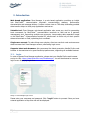
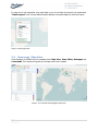
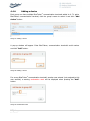
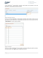
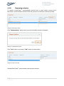
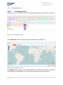
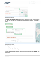
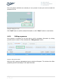
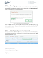
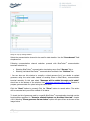
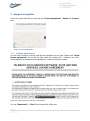
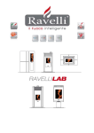
Zone Manager User’s Manual 1|Page S o l u t i o n s © 2 0 1 2 E M A – W i r e l e s s d a t a Document Information Document Title : Zone Manager User’s Manual Document Version : V1.1.8 Released (dd-mm-yyyy): 15.03.2013 Document ID : UM 2013-1-ZONE-MANAGER Document Author: D. Puhar, M. Verk, I. Pirnat , M. Kožuh 2|Page S o l u t i o n s © 2 0 1 2 E M A – W i r e l e s s d a t a Table of Contents 1. Definitions, Acronyms and Abbreviations .................................................................... 6 2. Introduction ............................................................................................................ 7 3. 4. 2.1. Login................................................................................................................ 7 2.2. Home page / Map View...................................................................................... 8 “Map View” tab ........................................................................................................ 9 3.1. Right hand side fleet map view ........................................................................... 9 3.2. Left hand side fleet table view .......................................................................... 10 3.2.1. Buttons .................................................................................................... 11 3.2.2. Devices list ............................................................................................... 12 3.2.3. Areas list .................................................................................................. 14 ”Zone Editor” tab ................................................................................................... 15 4.1. About geozones .............................................................................................. 16 4.2. Geozone parameters ....................................................................................... 17 4.3. Geozone examples .......................................................................................... 19 4.3.1. EXAMPLE 1: Single geozone....................................................................... 19 4.3.2. EXAMPLE 2: Two geozones overlapping ...................................................... 21 4.4. Managing groups ............................................................................................ 23 4.4.1. Creating a group....................................................................................... 24 4.4.2. Renaming a group .................................................................................... 25 4.4.3. Deleting a group ....................................................................................... 25 4.4.4. Adding a device ........................................................................................ 26 4.4.5. Removing a device.................................................................................... 28 4.5. Managing areas............................................................................................... 29 4.5.1. Creating an area ....................................................................................... 29 4.5.2. Defining geographical points using map tool ............................................... 30 3|Page S o l u t i o n s © 2 0 1 2 E M A – W i r e l e s s d a t a 4.5.3. Defining geographical points using text insertion tool ................................... 32 4.5.4. Saving an area ......................................................................................... 35 4.5.5. Editing an area ......................................................................................... 35 4.5.6. Removing an area..................................................................................... 37 4.6. 5. 6. 7. Managing geozones ......................................................................................... 39 4.6.1. Creating a geozone ................................................................................... 39 4.6.2. Editing a geozone ..................................................................................... 44 4.6.3. Removing a geozone ................................................................................. 46 4.6.4. Uploading single geozone to the terminals .................................................. 46 4.6.5. Removing single geozone from the terminals .............................................. 48 4.6.6. Synchronizing geozones list ....................................................................... 50 4.6.7. Exporting geozones list to a file.................................................................. 52 4.6.8. Geozone related features on the Map View tab............................................ 53 “Messages” tab ...................................................................................................... 57 5.1. Message listing ............................................................................................... 57 5.2. Messages filtering............................................................................................ 58 5.3. Additional message information ........................................................................ 60 “Commands” tab.................................................................................................... 61 6.1. POLL command ............................................................................................... 62 6.2. RIC command ................................................................................................. 64 6.3. HRDR command .............................................................................................. 66 6.4. STANDBY command ........................................................................................ 68 6.5. STANDBY SETUP command .............................................................................. 70 Support navigation ................................................................................................. 72 7.1. License agreement .......................................................................................... 72 7.2. Help ............................................................................................................... 73 7.3. Logout ........................................................................................................... 73 4|Page S o l u t i o n s © 2 0 1 2 E M A – W i r e l e s s d a t a 8. Session expired ..................................................................................................... 74 9. Disclaimer ............................................................................................................. 75 10. Copyright ........................................................................................................... 75 5|Page S o l u t i o n s © 2 0 1 2 E M A – W i r e l e s s d a t a 1. Definitions, Acronyms and Abbreviations Item Explanation EMA EMA d.o.o. Celje, developing telematics products and solutions, headquartered in Celje, Slovenia. BlueTraker® communication A range of tracking and communication terminals produced by EMA. terminal BT BlueTraker® communication terminal TDS3 Telematics Data Server (TDS), current version no. 3 A modular suite of server software components enabling two way communication between BlueTraker® communication terminals and the end data recipient (application or server). TDS supports communication using various to and from communication channels eliminating need to translate BlueTraker® tLink data format at the client’s side. Geozone A geozone is defined by a geographical area and a set of required and optional parameters (see 2.1.). Its purpose is to request BlueTraker® communication terminal behavioral changes according to programmed specifics. TrakerUtils An application enabling communication with BlueTraker® communication terminal via a serial cable connection. Mainly used for settings arrangements and testing. 6|Page S o l u t i o n s © 2 0 1 2 E M A – W i r e l e s s d a t a 2. Introduction Web based application: Zone Manager is a web based application providing an insight into BlueTraker® communication terminal’s communication statuses, performance characteristics and message delivery. It offers a direct view on TDS data, eliminating possible data transfer delays to third party applications and server. Valuable tool: Zone Manager web based application also serves as a tool for generating basic commands for BlueTraker® communication terminals on field and as a geozone management tool. Supporting multiple user accounts, incorporating data separation based on the BlueTraker® communication terminal ID, allows users to focus only on their specific data and terminals on field, optimizing their workload. Single user account: To make things even simpler, client can use their web service access data to access their Zone Manager account, eliminating login errors. Supports latest web browsers: We recommend the latest generation Mozilla Firefox web browser to be used due to its great JavaScript performance, supporting all available features. 2.1. Login In order to access Zone Manager application, please start your Mozilla Firefox web browser and go to URL: https://data.bluetraker.com/ZoneManager/. You will be directed to a secure login screen displaying login form. Image 1: Zone Manager login screen Please enter your username and password. Click “Login” button to proceed. Once you have entered application a Map View tab will be displayed. 7|Page S o l u t i o n s © 2 0 1 2 E M A – W i r e l e s s d a t a In case you do not remember your login data or you do not have an account yet, please click “Email support” link. Use pre-defined email address and email subject to send an inquiry. Image 2. Email support link 2.2. Home page / Map View Zone Manager is divided into four separate tabs: Map View, Zone Editor, Messages and Commands. This manual will guide you through each one in details. Image 3: Four separate tabs highlighted (Map View) 8|Page S o l u t i o n s © 2 0 1 2 E M A – W i r e l e s s d a t a 3. “Map View” tab “Map View” tab serves as your start screen and simplifies your fleet overview (Image 4). It allows you to access majority of the application functions and basic fleet info. 3.1. Right hand side fleet map view On the right hand side, fleet map overview is available. It displays last known positions of all BlueTraker® communication terminals that are part of the fleet under this user account. Image 4: Map view (right handside) 9|Page S o l u t i o n s © 2 0 1 2 E M A – W i r e l e s s d a t a 3.2. Left hand side fleet table view On the left hand side, fleet table overview is available, including active BlueTraker® communication terminals (have sent at least 1 message) and the areas list applicable to your fleet under this user account. Image 5: Left hand side 10 | P a g e S o l u t i o n s © 2 0 1 2 E M A – W i r e l e s s d a t a 3.2.1. Buttons You are able to find three specific buttons at the top of the left hand side: Image 6: Buttons specified above “Refresh” button – click it to refresh BlueTraker® communication terminals list and geographical map data. Image 7: Refreshed devices list (orange showing the updated data after refresh process finished) “Show all areas” button – click it to display all areas list items (Image 5, blue square). Image 8: All fleet areas displayed (blue and red) “Hide all areas” button – click it to hide all areas list items (Image 5, blue square). 11 | P a g e S o l u t i o n s © 2 0 1 2 E M A – W i r e l e s s d a t a 3.2.2. Devices list Under the buttons area all fleet BlueTraker® communication terminals are shown in an organized list. Each BlueTraker® communication terminal’s ID is displayed alongside last message GPS and received times. Time difference between GPS and received time defines the amount of time BlueTraker® communication terminal needs to deliver message to TDS server. If needed, BlueTraker® communication terminals list can be sorted by column by clicking column display name. Image 9: Column display name is grayed out on mouse hover Some of the table columns are hidden by default to preserve map size. If you need additional columns to be displayed, click the arrow sign on the top right table side. To select additional column, click its name. Image 10: Click the green marked areas 12 | P a g e S o l u t i o n s © 2 0 1 2 E M A – W i r e l e s s d a t a To display last known BlueTraker® communication terminal position on map, click BlueTraker® communication terminal line on the list (Image 10). Last received position report location will be shown on the map (Image 11). Image 11: Last arrow marked position displayed on the map If movement is detected, BlueTraker® communication terminal last reported position is shown as an arrow pointing to BlueTraker® communication terminal movement direction (nr. 1 & 2 - Image 11). In case of multiple positions displayed on the map, selected BlueTraker® communication terminal’s position is highlighted using a white square (nr.1 – Image 10). Other, non-selected BlueTraker® communication terminal’s positions are not highlighted (nr.2 – Image 10). If the BlueTraker® communication terminal is stationary, its position is shown as a dot (Image 12). Image 12: Last dot marked position displayed on the map 13 | P a g e S o l u t i o n s © 2 0 1 2 E M A – W i r e l e s s d a t a 3.2.3. Areas list Under the BlueTraker® communication terminal list section, all fleet areas are shown in an organized list. Image 13: List of fleet areas Each area name is displayed alongside its defined color. If needed, areas list can be sorted by name by clicking column title. Image 14: Column display name is grayed out on mouse hover To display a specific area on the map, use the check box on the list’s left hand side column. The checked areas will be displayed. You can hide them by upchucking them. Image 15: Selected area displayed on the map 14 | P a g e S o l u t i o n s © 2 0 1 2 E M A – W i r e l e s s d a t a 4. ”Zone Editor” tab “Zone Editor” tab allows users to manage fleet geozones. Image 16: Zone Editor tab “Zone Editor” tab is divided to: Geozone management (green top section); Area management (orange bottom section). Each section is a separate management tool. You need to first create an area, before you create a geozone. Area is a pre-requisite for creating a geozone. 15 | P a g e S o l u t i o n s © 2 0 1 2 E M A – W i r e l e s s d a t a 4.1. About geozones What is a geozone? A geozone is represented as a “geographical area", a simple polygon. Each geozone is defined by a series of geographical points, defining geozone borders. Usually these areas are of special interest, restricted to regular shipping or areas under special regulations (referred as “Area” in the next chapters). What does the geozone define? A geozones defines BlueTraker® communication terminal’s special behavior on entry, during navigation inside and on exit from a geozone. Most frequent setup defines different terminal reporting frequency during navigation inside geozone. Terminal can also be setup to alert an operator on entry and on exit from geozone. There is also room to add additional behavior specifics per each geozone. How many geozones can we use, how are to be defined? BlueTraker® communication terminal can hold up to 100 geozones, each defined by up to 100 geographical points, each defined by longitude and latitude in WGS84 format, and 9 attributes defining specific behavioral requirements for BlueTraker® communication terminal. What about the geozone overlap? Multiple geozones containing different set of attributes are able to use a single area, overlap. This approach can be used to define different BlueTraker® communication terminal behaviors during different times of year (winter and summer specifics as an example). BlueTraker® communication terminal specifics for supporting geozones BlueTraker® communication terminal, firmware v3.0 or higher; Geozone firmware option must be included in terminal firmware; Additional hardware accessories might be needed, depending on initial purchase. 16 | P a g e S o l u t i o n s © 2 0 1 2 E M A – W i r e l e s s d a t a 4.2. Geozone parameters Field Description Comment Geozone name Unique geozone name. Max. length is 50 characters. Geozone enabled Flag indicating geozone being enabled or disabled. Name of the area defined as a polygon. Area Area will be shown on the map. Type of the geozone. Current values are: National, Satellite. This property impacts other settings. Starting date/time Start date/time when geozone becomes active. This field is optional. If value is entered then value needs to be entered into “Ending date/time” field. Ending date/time Ending date/time when geozone becomes inactive. This field is optional. If value is entered then value needs to be entered into “Starting date/time” field. Channel Communication channel used to send messages while position is defined in this geozone. This field is enabled if selected geozone’s type is “National”. Reporting interval Reporting interval in minutes. Values between 0 and 1080 or 1440 (24 hr) are valid. Transmission interval in minutes. This field is enabled if selected geozone’s type is “National”. Geozone type Transmission interval Transmit on battery Vessel speed below Values between 0 and 1080 or 1440 (24 hr) are valid. Flag indicating reports should be transmitted when device functions on battery power. This field is enabled if selected geozone’s type is “National”. When vessel navigates on speed lower than here defined, reduced reporting interval applies. Values can be entered in knots “kn” or kilometres per hour “km/h”. This field is optional. If value is entered then values need to be entered into “Unit” and “Low speed reporting interval” fields. For “kn”: Values between 0 and 137 are valid. For “km/h”: Values between 0 and 255 are valid. 17 | P a g e S o l u t i o n s © 2 0 1 2 E M A – W i r e l e s s d a t a Unit Speed unit. Supported speed units: “kn” and “km/h”. Low speed reporting interval Reporting interval in minutes used when on low speed. Valid value is between 0 and 1080 or 1440 (24 hr). 18 | P a g e S o l u t i o n s © 2 0 1 2 E M A – W i r e l e s s d a t a 4.3. Geozone examples 4.3.1. EXAMPLE 1: Single geozone BlueTraker® communication terminal settings: Reporting interval: 120 minutes “GeozoneBlue” geozone attributes: Reporting interval: 60 minutes Geozone type: Satellite Vessel speed below: None Low speed reporting interval: None Image 17: Single geozone on a map 19 | P a g e S o l u t i o n s © 2 0 1 2 E M A – W i r e l e s s d a t a Messages to be received based on the above BlueTraker® communication terminal settings and geozone attributes: Message Type A B C D E F G H I J K L M N O Navigation Navigation Entry Navigation Navigation Navigation Exit Navigation Entry Navigation Navigation Exit Navigation Navigation Navigation 20 | P a g e S o l u t i o n s Geozone GeozoneBlue GeozoneBlue GeozoneBlue GeozoneBlue GeozoneBlue GeozoneBlue GeozoneBlue GeozoneBlue GeozoneBlue Time 12:00 14:00 15:30 16:30 17:30 18:30 19:15 21:15 22:00 23:00 00:00 00:25 02:25 04:25 06:25 © 2 0 1 2 E M A – W i r e l e s s d a t a 4.3.2. EXAMPLE 2: Two geozones overlapping BlueTraker® communication terminal settings: Reporting interval: 120 minutes “GeozoneBlue” geozone attributes: Reporting interval: 60 minutes Geozone type: Satellite Vessel speed below: None Low speed reporting interval: None “GeozoneGreen” geozone attributes: Reporting interval: 30 minutes Geozone type: Satellite Vessel speed below: None Low speed reporting interval: None Image 18: Two geozones overlapping 21 | P a g e S o l u t i o n s © 2 0 1 2 E M A – W i r e l e s s d a t a Messages to be received based on the above BlueTraker® communication terminal settings and geozones attributes: Message Type A B C D E F G H I J K L M N O P R S T U Navigation Navigation Entry Navigation Entry Navigation Exit Navigation Navigation Navigation Navigation Entry Navigation Navigation Navigation Exit Navigation Navigation Exit Navigation 22 | P a g e S o l u t i o n s Geozone GeozoneGreen GeozoneGreen GeozoneBlue GeozoneGreen GeozoneGreen GeozoneBlue GeozoneBlue GeozoneBlue GeozoneBlue GeozoneGreen GeozoneGreen GeozoneGreen GeozoneGreen GeozoneBlue GeozoneGreen GeozoneGreen GeozoneGreen Time 01:00 03:00 03:45 04:15 04:30 05:00 05:25 06:25 07:25 08:25 09:25 09:45 10:15 10:45 11:15 11:30 12:00 12:30 12:40 14:40 © 2 0 1 2 E M A – W i r e l e s s d a t a 4.4. Managing groups Group’s management is used to group individual BlueTraker® communication terminals on field. You are then able to send a geozone or sync command to this group of BlueTraker® communication terminals. You do not need to individually select them every time you decide to perform an action. Image 19: Manage groups button Click the “Manage groups” button and manage groups pop-up window will open. Image 20: Groups management window You are able to see the available groups in groups list (orange frame). Image 21: Selected group 23 | P a g e S o l u t i o n s © 2 0 1 2 E M A – W i r e l e s s d a t a Select a group by clicking its name and a list of BlueTraker® communication terminals included in the group will be displayed in the BlueTraker® communication terminals list (green frame – Image 28). 4.4.1. Creating a group You can add a new group to a list of groups by clicking “Add group” button. Image 22: Add group button A pop-up window will appear. Image 23: Add group pop-up window Enter group name and click “Add” button to proceed. 24 | P a g e S o l u t i o n s © 2 0 1 2 E M A – W i r e l e s s d a t a 4.4.2. Renaming a group You can rename a selected group by clicking a “Rename group” button when group is selected. Image 24: Function buttons A pop-up window will appear. Image 25: Rename group window Enter a new group name and click “Save”. 4.4.3. Deleting a group You can delete a selected group by clicking a “Delete group” button when a group is selected (Image 32). A pop-up window will appear. Image 26: Delete group window Click “Yes” button to proceed and “No” button to cancel your action. 25 | P a g e S o l u t i o n s © 2 0 1 2 E M A – W i r e l e s s d a t a 4.4.4. Adding a device Each group can have multiple BlueTraker® communication terminals added to it. To add a BlueTraker® communication terminal, click the group’s name to select it and click “Add device” button. Image 27: Adding a device A pop-up window will appear. Enter BlueTraker® communication terminal’s serial number and click “Add” button. Image 28: Adding a device If a wrong BlueTraker® communication terminal’s number was entered (not assigned to this user account) a warning exclamation mark will be displayed when pressing the “Add” button. Image 29: Exclamation mark 26 | P a g e S o l u t i o n s © 2 0 1 2 E M A – W i r e l e s s d a t a Correct BlueTraker® communication terminal’s serial number and proceed to see new BlueTraker® communication terminal on the list. Image 30: New device on the list If you do not have a BlueTraker® communication terminal’s serial number at hand, you can also select one of the BlueTraker® communication terminals from the user account list. Click “Select device” to open a pop-up window. Image 31: Devices list Select any number of BlueTraker® communication terminals by clicking the check box next to the serial number. Click “Add” button to add them to the list. 27 | P a g e S o l u t i o n s © 2 0 1 2 E M A – W i r e l e s s d a t a 4.4.5. Removing a device To remove a BlueTraker® communication terminal from a group select a group and a BlueTraker® communication terminal inside the group to be removed by clicking its name. Image 32: Removing a device Click “Delete device” button and a pop-up confirmation window will appear. Image 33: Confirmation window Click “Yes” button to proceed or “No” button to cancel action. Image 34: Device removed Selected BlueTraker® communication terminal was removed. 28 | P a g e S o l u t i o n s © 2 0 1 2 E M A – W i r e l e s s d a t a 4.5. Managing areas 4.5.1. Creating an area Adding an area on a map is done using area management section of the screen (Image 24). Image 35: Area management section Click “Add area” button to display area management screen (Image 35). Image 36: Area management screen Use “Name” field to add your area’s name/title/mark. Proceed with area color selection by double-clicking the displayed color. A pop-up color selection tool will be displayed. 29 | P a g e S o l u t i o n s © 2 0 1 2 E M A – W i r e l e s s d a t a Image 37: Color selection tool Using your mouse pointer, click the preferred color inside the color scheme (orange frame) or use RGB selectors under the color scheme. When you are satisfied, please click “OK” button. If you do not wish to change the pre-selected color then click “Cancel” button. Proceed with defining the area geographical points. You can do this using two options. 4.5.2. Defining geographical points using map tool Image 38: Area map tool To make it easier for you, once you hover over the map, your mouse pointer will display a blue circle to inform you the map tool is being used. If the blue circle does not appear automatically, the map tool has been turned off. In this case, you will need to open area management screen again, using “Add area” button on “Zone Editor” tab. To start drawing an area use a single click for the first geographical point. Area usually holds many geographical points, therefore move the mouse to extend the border line and make a second single click to mark second geographical point. To make a triangle you continue extending border line to make a third geographical point. Use double clicks 30 | P a g e S o l u t i o n s © 2 0 1 2 E M A – W i r e l e s s d a t a to mark the next geographical point if you wish to stop drawing border lines and finish the triangle area. Image 39: Drawing triangular area If you wish to proceed and make a more complex area, use single clicks until you entered all geographical points and mark the last one using double click. Image 40: Finished 4 geographical points area If you are not completely satisfied, you can edit the finished area by clicking it. This reactivates the drawing and allows you to move area geographical points. Image 41: Reactivated area 31 | P a g e S o l u t i o n s © 2 0 1 2 E M A – W i r e l e s s d a t a Between previously defined geographical points, new possible geographical points are offered to be used (Image 50). Click them and hold the click to move them to the desired place. You can add many additional points. Image 42: Adding new geographical points You are also able to decide to remove a single specified geographical point by hovering over it while holding “Shift” and “Delete” keyboards keys. ! Once you use this option, you cannot reverse it! 4.5.3. Defining geographical points using text insertion tool Click “Insert coordinates” button on area management screen (Image 44). A pop-up window will appear. Prepare a text file containing geographical points using the following format: [ Longitude ],[ latitude ] [degree in decimal numbers],[degree in decimal numbers] Please check Image 43 for further reference. 32 | P a g e S o l u t i o n s © 2 0 1 2 E M A – W i r e l e s s d a t a Image 43: Prepared area coordinates Select the text file content and use COPY-PASTE the selection inside the “Insert coordinates” field. Image 44: Insert coordinates window Image 45: Inserted coordinates 33 | P a g e S o l u t i o n s © 2 0 1 2 E M A – W i r e l e s s d a t a When finished, the click “Add coordinates” button to save. The area will be displayed on the map. Image 46: Area defined by inserted coordinates You can additionally modify an area using the map tool. Single click on the area will allow you to modify it. Image 47: Area ready to be additionally modified 34 | P a g e S o l u t i o n s © 2 0 1 2 E M A – W i r e l e s s d a t a 4.5.4. Saving an area Once you have finished, click the “Add” button to save your selection. Image 48: Finishing the input If the defined area is not ok use “Clear” button to eliminate it. ! Once you use this button, you cannot reverse the action! Click the “Close” button to discard entry or changes. 4.5.5. Editing an area If you wish to only edit/modify an existing area, you will need to create a new area based on the prior information and delete the old one. This limitation is built in with a purpose. Please select the area from the list by clicking its name. You can only select one area at a time. Image 49: Selecting an area When you have selected an area from the list, click the “Create from selected area” button. This will open area management screen. 35 | P a g e S o l u t i o n s © 2 0 1 2 E M A – W i r e l e s s d a t a Image 50: Area management screen You can find all previously defined points displayed. If you wish to modify the area on the map, please click on it and move the geographical points. Please do rename the area as you are not able to save these changes using the same area name. Once you have finished, click the “Add” button to save your selection. Image 51: Finishing the input If the defined area is not ok use “Clear” button to eliminate it. ! Once you use this button, you cannot reverse the action! Click the “Close” button to discard entry or changes. If you preserved the changes a new area will be added to the list. 36 | P a g e S o l u t i o n s © 2 0 1 2 E M A – W i r e l e s s d a t a Image 52: New area added to the list 4.5.6. Removing an area If you wish to remove an area, you will need to remove it from the list. Please select an area from the list by clicking its name. You can only select one area at a time. Image 53: Selecting an area to be removed When area is selected click the “Remove area” button. A confirmation pop-up window will appear. 37 | P a g e S o l u t i o n s © 2 0 1 2 E M A – W i r e l e s s d a t a Image 54: Confirmation pop-up window If you wish to proceed, click “Yes” button. In you wish to cancel the action, click “No” button. If an area is assigned to at least 1 geozone you will not be able to delete it. A pop-up information window will be shown. If you wish to proceed with area removal, you will first need to remove all geozones connected to it. Click “OK” button to exit. Image 55: Pop-up information window 38 | P a g e S o l u t i o n s © 2 0 1 2 E M A – W i r e l e s s d a t a 4.6. Managing geozones 4.6.1. Creating a geozone In order to create a new geozone be certain that you have at least one area available for the new geozone to use it. Please check the instructions how to create an area here (4.5.1. Creating an area). To start creating a geozone click “Add geozone” button on “Zone Editor” geozone management section (Image 24 – green frame). Image 56: Adding a geozone Following the button click a pop-up geozone management window will appear. Image 57: Geozone management window 39 | P a g e S o l u t i o n s © 2 0 1 2 E M A – W i r e l e s s d a t a Enter geozone name/tag to “Geozone Name” field. Once you defined it, you need to proceed with other required fields (marked *) inside the “Attributes” section. This section uses a scroll down tool on the right hand side, next to the map. To display other attributes, please scroll down using a mouse pointer. Image 58: Entering geozone attributes Geozone attributes define BlueTraker® communication terminal’s behaviour when positioned inside the geozone area and also some general geozone attributes like “Enabled/Disabled”. “Geozone enabled” check box is used to specify if BlueTraker® communication terminal should use this geozone or not. Image 59: Check box selection 40 | P a g e S o l u t i o n s © 2 0 1 2 E M A – W i r e l e s s d a t a If this check box is not selected, BlueTraker® communication terminal holds this geozone inside memory but does not use it during operation. If check box is selected BlueTraker® communication terminal will use this geozone during operation. Use “Area” dropdown list to select a pre-defined geographical area which will define geozone geographical area coverage. Image 60: Selecting pre-defined area If an area you required is not listed, please use “Add area” button. A pop-up area management window will be displayed. Follow create area instructions here (4.5.1 Creating an area) to create it. Once you have selected an area to be used a geozone type needs to be defined. “Geozone type” dropdown list holds the possible types to be selected. Image 61: Selecting geozone type Once you have selected geozone type to be used a geozone validity period needs to be defined. 41 | P a g e S o l u t i o n s © 2 0 1 2 E M A – W i r e l e s s d a t a Image 62: Selecting date/time Enter start and end date/time or select it using calendar tool. Once you have selected the start and end date /time proceed with reporting settings attributes. Scroll down to display. Image 63: Reporting settings Reporting settings are set for: National reporting; Vessel low speed reporting. To setup national settings first select communications channel from the “Channel” field dropdown list. 42 | P a g e S o l u t i o n s © 2 0 1 2 E M A – W i r e l e s s d a t a Image 64: National reporting attributes Following communication channel selection enter “Reporting interval” in minutes. Reporting interval defines messages delivery frequency. Leave “Transmission interval” field empty as it is not being used. Proceed with “Transmit on battery” check box selection if you wish BlueTraker® communication terminal would keep transmitting when using backup battery power. Once national reporting attributes have been defined proceed with “Vessel low speed reporting” attributes, entering minimum vessel speed allowed before switching to vessel low speed reporting mode. Image 65: Defining vessel low speed reporting attributes Use the “Vessel speed below” field to enter number value. Preferably use knots “kn” unit of measure for vessels. In special cases kilometres per hour “km/h” can also be used. Use the “Unit” field to select a unit of measure from the dropdown list. Additionally enter preferred reporting interval frequency (message delivery frequency) in minutes. Use the “Low speed reporting interval” field. This reporting interval frequency will be used when vessel’s speed is lower than the specified one. 43 | P a g e S o l u t i o n s © 2 0 1 2 E M A – W i r e l e s s d a t a Once all goezone attributes are entered you can proceed to save your work and add this geozone to a list. Image 66: Saving your work Click “Add” button to confirm entered information or click “Close” button to cancel action. 4.6.2. Editing a geozone Once geozone is entered you are also able to edit its attributes information by clicking geozone name to select it. Once selected click “Edit geozone” button. Image 67: Edit geozone button After the click a geozone management pop-up window will appear. This window also offers graphical geozone area display on the right hand side. 44 | P a g e S o l u t i o n s © 2 0 1 2 E M A – W i r e l e s s d a t a Image 68: Editing a geozone Use the same instructions as for creating geozone (4.6.1 Creating geozone) to edit its attributes. Once the geozone is correctly edited click the “Save” button to confirm changes or click the “Close” button to cancel action. A pop-up confirmation window will appear. Image 69: Editing a geozone confirmation window Select “I agree” check box and click “Yes” button to proceed. Click “No” button if you wish to cancel the action. Geozone will be immediately edited on all BlueTraker® communication terminals. 45 | P a g e S o l u t i o n s © 2 0 1 2 E M A – W i r e l e s s d a t a 4.6.3. Removing a geozone An existing geozone can be removed. To remove it from the list and BlueTraker® communication terminals select a geozone from the list and click the “Remove geozone” button. A confirmation pop-up window will appear. Image 70: Removing a geozone confirmation window Select “I agree” check box and click “Yes” button to proceed. Click “No” button if you wish to cancel the action. Geozone will be immediately removed from all the BlueTraker® communication terminals. 4.6.4. Uploading single geozone to the terminals Once you have created or edited a geozone you can upload it to the selected BlueTraker® communication terminals. Select the geozone on the list by clicking its name and click “Send geozones to devices” button. Image 71: Send geozones button A pop-up settings window will appear. 46 | P a g e S o l u t i o n s © 2 0 1 2 E M A – W i r e l e s s d a t a Image 72: Pop-up settings window Select the communication channel to be used for data transfer. Use the “Use channel” field dropdown list. Following communication channel selection proceed with BlueTraker® communication terminals selection by: Selecting BlueTraker® communication terminals groups from “Groups” list or Selecting individual BlueTraker® communication terminals from “Devices” list. ! You can also use this window to compile a virtual geozone list if you decide to upload geozones using the serial cable instead of sending them to BlueTraker® communication terminal remotely! In this case select “Geozone will be added through serial cable” check box at the bottom of the window. Use “Exporting geozones list to a file” function to prepare geozones data for upload using the serial cable. Click the “Send” button to proceed. Click the “Close” button to cancel action. The action will be executed and you will be notified of its status. To check the list of geozones used by a specific BlueTraker® communication terminal use the functionalities explained in “Geozone related features on the Map View tab” chapter 4.6.8. Selecting “Show geozones list on device” option will open screen as shown on the image below. 47 | P a g e S o l u t i o n s © 2 0 1 2 E M A – W i r e l e s s d a t a Image 73: List of geozones per device 4.6.5. Removing single geozone from the terminals If you decide to eliminate a specific geozone from terminals select the geozone on the list by clicking its name and click “Remove geozone from devices” button. Image 74: Remove geozone button A pop-up selection window will appear. 48 | P a g e S o l u t i o n s © 2 0 1 2 E M A – W i r e l e s s d a t a Image 75: Remove geozone window To send a command using a specific communication channel use the “Use channel” dropdown list. As a selected geozone has already been added to one or more BlueTraker® communication terminals, these BlueTraker® communication terminals are displayed inside “Devices” list. Click the “Remove” button if you wish to proceed or click the “Close” button if you wish to cancel the action. To check the list of geozones used by a specific BlueTraker® communication terminal after a geozone was removed, use the functionalities explained in “Geozone related features on the Map View tab” chapter 4.6.8. Selecting “Show geozones list on device” option will open screen as shown on the image below. 49 | P a g e S o l u t i o n s © 2 0 1 2 E M A – W i r e l e s s d a t a Image 76: List of geozones per device 4.6.6. Synchronizing geozones list Geozones synchronization is usefull when many geozones have been edited, deleted or created. It checks the geozones previously uploaded to BlueTraker® communication terminals and compares it with the current geozones list in Zone Manager application. If there are any differences between both lists the process synchronizes the lists to be the same (example: calendar synchronization between team members). Click “Request sync” button above the geozones list. Image 77: Geozones synchronization button A pop-up synchronization setup window will appear. 50 | P a g e S o l u t i o n s © 2 0 1 2 E M A – W i r e l e s s d a t a Image 78: Synchronization window To send the command and received data using specific communication channel use “Use channel” dropdown list. Select a group of BlueTraker® communication terminals or a single BlueTraker® communication terminal from the “Groups” and “Devices” list. Click the “Send” button if you wish to proceed or click the “Close” button if you wish to cancel the action. Sync command will be send to the BlueTraker® communication terminals. When a BlueTraker® communication terminal responds to the command with a status message, geozone synchronization will be executed. Sync status can be viewed on “Show geozones list on device” (4.6.8 Geozone related features on the Map View tab) window. Please note: !If geozones have been marked to be added to specific BlueTraker® communication terminals using a serial cable, this synchronization will not know this and will update these terminals remotely. Therefore make sure you have finished the manual upload on all activated BlueTraker® communication terminals! 51 | P a g e S o l u t i o n s © 2 0 1 2 E M A – W i r e l e s s d a t a 4.6.7. Exporting geozones list to a file Use this function if you want to upload the geozones directly to a BlueTraker® communication terminal using the TrakerUtils application and a direct cable connection. This function is complementary to “Geozone will be added through serial cable” function described in “Uploading single geozone to the terminals”, chapter 4.6.4. Click the “Export to file” button above the geozones list. Image 79: Export button A pop-up export window will appear. Image 80: Geozone export window Enter file name into “File name” field without using spaces between characters. Pre-defined “geozones” value can be changed. Image 81: Appropriate file name 52 | P a g e S o l u t i o n s © 2 0 1 2 E M A – W i r e l e s s d a t a Image 82: Warning when using spaces in file name Select check boxes next to geozones inside the list to mark them for export. Once geozones are selected, click the »Export” button to proceed or click the “Close” button to cancel the action. Image 83: Exporting file Once the save pop-up window appears, select “Save file” option and click “Ok”. Saved file can be used later. Use the “TrakerUtils” terminal management application to upload the geozones using a serial cable. TrakerUtils application can be downloaded from the web or can be sent to you by your EMA support technician. 4.6.8. Geozone related features on the Map View tab Navigate to the “Map View” tab. On the left hand side of the screen, the fleet table overview is available, including the BlueTraker® communication terminals and the areas list applicable to your fleet under this user account. Select a BlueTraker® communication terminal from the BlueTraker® communication terminals list and click its name to select it. Use right button click to display additional BlueTraker® communication terminal options. 53 | P a g e S o l u t i o n s © 2 0 1 2 E M A – W i r e l e s s d a t a Image 84: Device's additional options OPTION 1: “Show geozones list on device”- click the first option on the list and a geozones overview pop-up window will appear. Image 85: Geozone list for a specific device This window displays current geozones inside the selected BlueTraker® communication terminal memory. Additionally, latest synchronization status is shown on the bottom side of the window. Status can display three different values: “Waiting for response” – the application is waiting for a response from the BlueTraker® communication terminal. “Geozone updates sent to the device” – the device is missing some of the geozones to be uploaded or a command containing deletion request is being processed by the BlueTraker® communication terminals. 54 | P a g e S o l u t i o n s © 2 0 1 2 E M A – W i r e l e s s d a t a “Device is up to date” – BlueTraker® communication terminal had processed all the requested changes and is updated accordingly. Click the “Close” button to close the window. OPTION 2: “Show geozone settings” – click the second option on the list and a geozones settings pop-up window will appear. Image 86: Setting automatic synchronization Unselect the check box if you are uploading geozones to the BlueTraker® communication terminal using the TrakerUtils application and a serial cable connection. If you enable this option, the next automatic synchronization server process will ignore “geozone serial cable upload” and will refresh BlueTraker® communication terminal’s geozone list remotely. This feature is built-in with a special purpose based on requirement. Click the “Save” button to proceed or click the “Close” button to cancel the action. 55 | P a g e S o l u t i o n s © 2 0 1 2 E M A – W i r e l e s s d a t a OPTION 3: ”Show track” - click the third option on the list and the selected BlueTraker® communication terminal’s route composed of the last 50 messages received will be shown on the right hand side map. Double clicking the map will zoom in. Image 87: Terminal's route If it happens there is no route shown and map focuses out as shown on the image below, please click the BlueTraker® communication terminal again to zoom it in accordingly. Image 88: Zoomed out map 56 | P a g e S o l u t i o n s © 2 0 1 2 E M A – W i r e l e s s d a t a 5. “Messages” tab “Messages” tab allows the received BlueTraker® communication terminal messages to be reviewed. Image 89: Messages tab All common message properties, such as latitude and longitude, are displayed in a table format, each row representing a single message. 5.1. Message listing You are able to see all received messages for a selected time period. The latest received messages are shown in the top table rows by scrolling the table you can see older messages. Image 90: Scrolling the messages table 57 | P a g e S o l u t i o n s © 2 0 1 2 E M A – W i r e l e s s d a t a 5.2. Messages filtering You may filter the messages in the table using various filters: Image 91: Message list filters By received time: use “From” and “To” fields to define start and end date/time. By PublicDeviceId: enter BlueTraker® communication terminal’s serial number. Image 92: Message list filters By Message Type: use “Type” field dropdown list to only display messages of a selected type. Message types are divided to standard and specially purposed: 58 | P a g e S o l u t i o n s © 2 0 1 2 E M A – W i r e l e s s d a t a Navigation (standard – regular navigation report); Diagnostic (standard – notification about device’s performance); IO (standard – Input/output signal); ASCII (standard – short data string transfer); Hello (standard – turn on notification); Activation (standard – activation notification); ACK (standard – acknowledge for received command); Geo_geofence (specially purposed – nav. mess. when geozones upgrade enabled ); Navigation_extended (specially purposed); SSAS (specially purposed). Geozone (not used anymore, only as a legacy); Image 93: Message list filters By Channel: use »Channel« field dropdown list to select specific communication channel: TCP BT (GPRS communication channel – devices from Q2.5 series G1 platform on); Iridium BT (IRIDIUM communication channel); xFTP BT (GPRS communication channel – devices up to Q2.5 series G1 platform). After you have selected all the desired filters, please click the »Reload« button. Clicking the button will refresh the list. Wait for the process to finish – see the processing indicator in the right top corner of the screen. Image 94: Processing indicator 59 | P a g e S o l u t i o n s © 2 0 1 2 E M A – W i r e l e s s d a t a 5.3. Additional message information Specific message types, such as an ASCII message carry additional information next to common message properties. You are able to display this additional information by displaying additional columns in the table. Image 95: Displaying additional columns Click the arrow sign on the top right table corner and select a column from the list. Click its name to display it. By double clicking the message row, a new pop-up window displaying all message parameters is shown. Image 96: All message parameters pop-up window 60 | P a g e S o l u t i o n s © 2 0 1 2 E M A – W i r e l e s s d a t a 6. “Commands” tab The “Commands” tab enables a number of basic commands to be sent to one or more BlueTraker® communication terminals. Commands enable remote BlueTraker® communication terminal management. Image 97: Commands tab and a list of possible commands Commands currently supported: POLL (returns current BlueTraker® communication terminal geographical position); RIC (changes current BlueTraker® communication terminal reporting interval); HRDR (returns all messages saved in internal BlueTraker® comm. terminal memory); Standby (sets BlueTraker® communication terminal reporting interval to 1/day); Standby Setup (sets BlueTraker® communication terminal reporting interval and Auto Exit Distance to specified values). 61 | P a g e S o l u t i o n s © 2 0 1 2 E M A – W i r e l e s s d a t a 6.1. POLL command Select a POLL command from the dropdown menu. Image 98: POLL commands setup Please select a BlueTraker® communication terminal from the BlueTraker® communication terminals list below the dropdown menu by selecting a check box next to the BlueTraker® communication terminal’s serial number. Once you selected all the BlueTraker® communication terminals you would like to send the POLL command to, please click the “Send” button to proceed. Image 99: Send button (bottom right hand side) A confirmation pop-up window will appear. To confirm POLL click the “Yes” button, otherwise click the “No” button. 62 | P a g e S o l u t i o n s © 2 0 1 2 E M A – W i r e l e s s d a t a Image 100: Command confirmation window Following the confirmation pop-up window, a second pop-up window will give you the option to select a communication channel to be used. Once you select a channel from the dropdown menu, POLL command will be sent to selected BlueTraker® communication terminals using selected communication channel. If you decide to select “Auto select” option from the list of possible communication channels, the last time utilized communication channel will be used (communication channel used to emit the last message from the terminal on the field). Image 101: Communication channel select window 63 | P a g e S o l u t i o n s © 2 0 1 2 E M A – W i r e l e s s d a t a 6.2. RIC command Select RIC command from the dropdown menu. Image 102: RIC command setup After command selection was made, a list of RIC command attributes appears below the command dropdown menu. Reporting interval change command is performed for each communication channel separately, therefore select a communication channel from the “Channel” dropdown menu. Continue with reporting interval length definition by entering a value in minutes into “Reporting interval (min)” field. Image 103: RIC command setup 64 | P a g e S o l u t i o n s © 2 0 1 2 E M A – W i r e l e s s d a t a Example: if you wish to receive a message report every 2 hours, please enter “120” (minutes). Proceed to select a BlueTraker® communication terminal from the BlueTraker® communication terminals list below the dropdown menu by selecting a check box next to the BlueTraker® communication terminal’s serial number. Once you selected all the BlueTraker® communication terminals you would like to send RIC command to, please click the “Send” button to proceed. Image 104: Send button (bottom right hand side) A confirmation pop-up window will appear. To confirm RIC command to be sent, please click the “Yes” button, otherwise click the “No” button. Image 105: Command confirmation window Following the confirmation pop-up window, a second pop-up window will give you the option to select a communication channel to be used. Once you select a channel from the dropdown menu, RIC command will be sent to selected BlueTraker® communication terminals using selected communication channel. If you decide to select “Auto select” option from the list of possible communication channels, the last selected communication channel will be used (referring to the previously sent command). Image 106: Communication channel selection window 65 | P a g e S o l u t i o n s © 2 0 1 2 E M A – W i r e l e s s d a t a 6.3. HRDR command Select a HRDR command from the dropdown menu. Image 107: HRDR command setup After command selection was made, a list of HRDR command attributes appears below the command dropdown menu. HRDR command requires “From” and “To” date/time values to be entered, defining the time period for messages download. Please use fields to enter values. You can also use a calendar tool by clicking an icon next to the fields. Please consider BlueTraker® communication terminal memory limitations when defining the interval. Proceed to select a BlueTraker® communication terminal from the BlueTraker® communication terminals list below the dropdown menu by selecting a check box next to the BlueTraker® communication terminal’s serial number. Once you selected all the BlueTraker® communication terminals you would like to send HRDR command to, please click the “Send” button to proceed. 66 | P a g e S o l u t i o n s © 2 0 1 2 E M A – W i r e l e s s d a t a Image 108: Send button (bottom right hand side A confirmation pop-up window will appear. To confirm HRDR command to be sent, please click the “Yes” button, otherwise click the “No” button. Image 109: Command confirmation window Following the confirmation pop-up window, a second pop-up window will give you the option to select a communication channel to be used. Once you select a channel from the dropdown menu, HRDR command will be sent to selected BlueTraker® communication terminals using selected communication channel. If you decide to select “Auto select” option from the list of possible communication channels, the last selected communication channel will be used (referring to the previously sent command). Image 110: Communication channel select window 67 | P a g e S o l u t i o n s © 2 0 1 2 E M A – W i r e l e s s d a t a 6.4. STANDBY command Select a STANDBY command from the dropdown menu. Image 111: STANDBY command setup After command selection was made, a list of STANDBY command attributes appears below the command dropdown menu. When using a STANDBY command it needs to be defined if BlueTraker® communication terminal will “Enter” or “Exit” STANDBY mode. STANDBY mode defines BlueTraker® communication terminal reporting frequency when in this mode. Please select a value from the dropdown menu. Proceed to select a BlueTraker® communication terminal from the BlueTraker® communication terminals list below the dropdown menu by selecting a check box next to the BlueTraker® communication terminal’s serial number. Once you selected all the BlueTraker® communication terminals you would like to send STANDBY command to, please click the “Send” button to proceed. Image 112: Send button (bottom right hand side) 68 | P a g e S o l u t i o n s © 2 0 1 2 E M A – W i r e l e s s d a t a A confirmation pop-up window will appear. To confirm STANDBY command to be sent, please click the “Yes” button, otherwise click the “No” button. Image 113: Command confirmation window Following the confirmation pop-up window, a second pop-up window will give you the option to select a communication channel to be used. Once you select a channel from the dropdown menu, STANDBY command will be sent to selected BlueTraker® communication terminals using selected communication channel. If you decide to select “Auto select” option from the list of possible communication channels, the last selected communication channel will be used (referring to the previously sent command). Image 114: Communication channel select window 69 | P a g e S o l u t i o n s © 2 0 1 2 E M A – W i r e l e s s d a t a 6.5. STANDBY SETUP command Select a STANDBY SETUP command from the dropdown menu. Image 115: STANDBY SETUP command setup After command selection was made, a list of STANDBY SETUP command attributes appears below the command dropdown menu. Standby setup COMMAND allows you to customize BlueTraker® communication terminal’s reporting interval after entering the STANDBY mode. You are also allowed to define “Avto exit distance”, distance vessel will travel before BlueTraker® communication terminal automatically exits STANDBY mode and resumes normal reporting interval. Please use appropriate units of measurement: minutes for reporting intervals and meters for avto exit distance. Proceed to select a BlueTraker® communication terminal from the BlueTraker® communication terminals list below the dropdown menu by selecting a check box next to the BlueTraker® communication terminal’s serial number. Once you selected all the BlueTraker® communication terminals you would like to send STANDBY command to, please click the “Send” button to proceed. 70 | P a g e S o l u t i o n s © 2 0 1 2 E M A – W i r e l e s s d a t a Image 116: Send button (bottom right hand side) A confirmation pop-up window will appear. To confirm STANDBY SETUP command to be sent, please click the “Yes” button, otherwise click the “No” button. Image 117: Command confirmation window Following the confirmation pop-up window, a second pop-up window will give you the option to select a communication channel to be used. Once you select a channel from the dropdown menu, STANDBY SETUP command will be sent to selected BlueTraker® communication terminals using selected communication channel. If you decide to select “Auto select” option from the list of possible communication channels, the last selected communication channel will be used (referring to the previously sent command). Image 118: Communication channel select window 71 | P a g e S o l u t i o n s © 2 0 1 2 E M A – W i r e l e s s d a t a 7. Support navigation On the top right hand side you can find the “License Agreement”, “Help2 and “Logout” links. Image 119: Top right hand side 7.1. License agreement You are able to access currently valid license agreement at any time. Please click “Show license agreement” link on the top right hand side (Image 119). Following your click, license agreement document will be displayed in a new web browser window. Image 120: License agreement opened in a new window You can “Download” or “Save” the document for offline use. 72 | P a g e S o l u t i o n s © 2 0 1 2 E M A – W i r e l e s s d a t a 7.2. Help You are able to access currently valid user’s manual at any time. Please click “Show help” link on the top right hand side (Image 118). Following your click, user’s manual document will be displayed in a new web browser window. Image 121: User's manual document opened in a new window You can “Download” or “Save” the document for offline use. 7.3. Logout In order to logout from the application, please click the “Logout” link on the top right hand side (Image 119). You will be logged out following your click. Image 122: Logout/login screen You can login again using the login form. 73 | P a g e S o l u t i o n s © 2 0 1 2 E M A – W i r e l e s s d a t a 8. Session expired Zone Manager application protects user from misuse of its user account by terminating session after user activity was no detected in the last half an hour. User is notified on session termination when it again tries to use functionality. Image 123: Session expired notification A red “Session Expired” notification is shown on the top navigation window side. We propose a user to take any notes of the changes done, but not committed. That’s why a user window last used is still visible, but not active. After you have made necessary notes, please click “Click here” link, to be redirected to the login screen. 74 | P a g e S o l u t i o n s © 2 0 1 2 E M A – W i r e l e s s d a t a 9. Disclaimer This User’s Manual (the “manual”) is provided on an "as is" and "as available" basis. EMA d.o.o. Celje (“EMA”) expressly disclaims all warranties of any kind, whether express or implied, including, but not limited to any warranties of merchantability, fitness for a particular use or purpose, non-infringement, title, accuracy of data and system integration. The manual may not be accurate and may be substantially modified or withdrawn. The entire risk arising out of the use of the manual remains with you, the EMA partner. In no event shall EMA be liable for any damage whatsoever arising out of the use of or inability to use the manual, even if EMA has been advised of the possibility of such damages. EMA is not obligated to provide updates, maintenance or technical support to the EMA partner. In no event shall EMA be obligated to make the manual commercially available. In no event shall EMA be liable for any indirect, incidental, special, consequential or exemplary damages, arising out of or related to your use of the manual, even if EMA has been advised of the possibility of such damages. The aggregate liability of EMA to you for all claims arising from or related to the manual is limited to amounts paid by you to EMA in connection therewith. If you are dissatisfied with any portion of the manual, your sole and exclusive remedy is to discontinue use of the manual. Telematic Data Server 3 (TDS) and Zone Manager are not designed for use in life support applications, or systems where malfunction or misuse of this product can reasonably be expected to result in personal injury or loss of life. 10. Copyright Manufacturer reserves the right to make changes without further notice to the product to improve reliability, function or design. This document and the information contained herein are the subject of copyright and intellectual property rights under the international conventions act. All rights reserved. No part of this document may be reproduced, stored in a retrieval system, or transmitted in any form by any means: electronic, mechanical or optical, in whole or in part, without the prior written permission from manufacturer. 75 | P a g e S o l u t i o n s © 2 0 1 2 E M A – W i r e l e s s d a t a