1
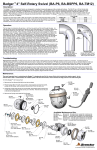
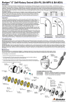
Badger TM 4" 40K Self-Rotary Swivel (BA-H6)
US Patent No. 5,964,414 & 6,059,202
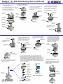
Disassembly:
1. Unscrew the Head (BA 440)
from the Nut (BA 002).
4. Unscrew the Seal Holder
(BA 406) from the Nut (BA 002).
7. Remove the Shaft Seal (EZ 029)
from the Seal Holder if it is damaged.
5. Remove the Shaft Seal (BA 007)
from the Nut if it is damaged.
2. Pull the Seal Assy (BA 400) out BA 406
of the Seal Holder (BA 406).
Seal Holder
8. Remove the O-Ring (BA 408) from
the Seal Holder if it is damaged.
6. Remove the Port Screw (BJ 026)
from the Nut.
3. Remove the O-Ring (WG 008)
from the Head if it is damaged.
9. Remove the Port Screw (BJ 026)
from the Seal Holder.
BA 007
Shaft Seal
BA 440
Head
BA 408
O-Ring
EZ 029
Shaft Seal
BA 401
Inlet Shaft
BA 002
Nut
BA 002
Nut
WG 008
O-Ring
BA 030
Wear Ring
BA 406
Seal Holder
BJ 026
Port Screw
BJ 026
Port Screw
BA 602-H6
Seal Assy
BA 401
Inlet Shaft
BA 406
Seal Holder
10. Press the Bearings
(SC212 007) off of the
Inlet Shaft.
BA 002
Nut
SC 212 007
Bearing
Assembly:
2. Press the Shaft Seal (EZ 029)
into the Seal Holder with the spring
side visible.
BA 401
Inlet Shaft
3. Press the O-Ring (BA 408) into
the groove on the Seal Holder.
1. Press the Bearings
(SC212 007) onto the
Inlet Shaft.
BA 408
O-Ring
SC 212 007
Bearing
EZ 029
Shaft Seal
spring side
BA 406
Seal Holder
BJ 026
Port Screw
BJ 026
Port Screw
6. Fill the Assembly with viscous fluid as
described in the maintenance section and
install the Port Screws.
4. Press the Shaft Seal (BA 007)
into the Nut with the spring side
visible.
BA 007
Shaft Seal
BA 002
Nut
BJ 026
Port Screw
BJ 026
Port Screw
5. Apply grease to the Seal lips in
the Seal Holder and the Nut; Slide
the Inlet Shaft with Bearings into the
Seal Holder (BA 406); apply antisieze to the threads and screw the
Seal holder into the Nut (BA 002),
taking care not to damage the
Seals. Torque to 25 ft-lbs.
BA 406
Seal Holder
BA 401
Inlet Shaft
BA 002
Nut
7. Insert the BA 602-H6 Seal Assy components into the Seal
Holder as shown below: First, install the Seat Face (BC 506).
Second, install the Seal Retainer (BC 520). Third, install the Carbide
Seat (BC 511) into the Seal Retainer with the chamfered end up.
Fourth, install the Compression Spring (BC 524) and the H.P. Seal
(BC 512-O) into the Inlet Seat (BA 422) and then insert the Inlet
Seat into the Seal Holder; note the orientation and relationship of
H.P. Seal and Carbide Seat. Finally, install the O-Ring (BC 040) into
the top of the Inlet Seat.
BC 040
O-Ring
BC 512-O
H.P. Seal
8. Install O-Ring (WG 008) over threads
and into groove on Head.
9. Apply anti-seize to threads on Head;
install Wear Ring (BA 030) onto the Nut
(BA 002); thread the Head into the Nut.
Tighten to 40 ft-lb.
BA 422
Inlet Seat
BC 524
Compression
Spring
BA 406
Seal Holder
WG 008
O-Ring
BC 512-O
H.P. Seal
BC 511
Carbide Seat
BC 520
Seal Retainer
BC 506
Seat Face
BA 602-H6 Seal Assy
© 2010 StoneAge®, All Rights Reserved
chamfer
BC 511
Carbide Seat
Seal & Seat Detail
BA 030
Wear Ring