1
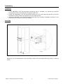
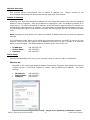
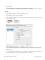
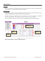
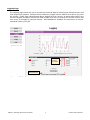
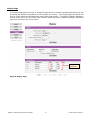
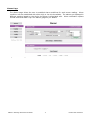
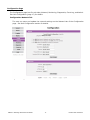
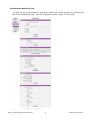
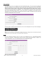
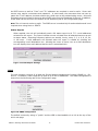
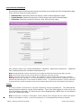
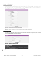
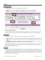
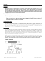
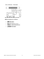
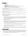
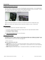
Instruction Manual Environmental Monitoring Unit Watchdog 1000 Series Firmware Version 3 Geist. 1821 Yolande Ave., Lincoln, NE 68521 800.432.3219 | 402.474.3400 | F: 402.474.4369 | www.geistglobal.com Contents Contents ............................................................................................................................2 Specifications ....................................................................................................................3 Overview 3 Environmental 3 Electrical 3 Networking 3 Data Formats 3 EMC Verification 4 Installation .......................................................................................................................5 Guidelines 5 Mounting 5 Network Overview 6 Default IP Address 6 Initial Setup 6 Web Interface ...................................................................................................................8 Overview 8 Sensors Page 8 Logging Page 9 Display Page 10 Alarms Page 11 Configuration Page 12 Unit Configuration ...........................................................................................................17 Network Configuration 17 Time and Date 18 E-Mail 18 SNMP 19 Accounts and Passwords 20 Telnet 20 Camera Configuration 21 Admin Information 21 Alarms .............................................................................................................................22 Alarm Notifications 22 Alarm Types 22 Thresholds 22 Sensors ...........................................................................................................................24 Overview 24 Internal Sensors 24 Temperature Offset 24 I/O Sensors 24 Remote Sensors 26 Data Logging and Display 26 Accessories .....................................................................................................................27 IP-Addressable Network Cameras 27 RSC Integration 27 Alternate Data Formats 27 Technical Support ...........................................................................................................28 Firmware Version 28 Firmware Updates 28 Resetting the Unit 28 Service and Maintenance 28 More Technical Support 28 Table of Figures ..............................................................................................................29 Revision History 30 GM1093 - Watchdog 1000 Series User Manual 2 Revision Date: 02/24/2015 Specifications Overview The Watchdog 1000 Environmental Monitoring Units provide remote environmental monitoring and alarming capability needed to detect climate conditions in data centers. The Watchdog 1000 Environmental Monitoring Units are equipped with a built-in web server. Web pages, including graphs, are generated by the unit to monitor environmental conditions within the cabinet. No software other than a web browser is required for operation and several data formats are available. The Watchdog 1000 have a built-in temperature sensor. The Watchdog 1000 has 16 expansion ports for the connection of external sensors and 3 I/O ports for optional remoter sensors. Watchdog 1000 support the use of network cameras. Environmental Temperature Operating: Storage: 10°C (50°F) min -25°C (-13°F) min 45°C (104°F) max 65°C (149°F) max Humidity Operating: Storage: 5% min 5% min 95% max 95% max (non-condensing) (non-condensing) Elevation Operating: Storage: 0 m (0 ft) min 0 m (0 ft) min 2000 m (6561 ft) max 15240 m (50000 ft) max Electrical 6-12 Volts DC, 2 Amps Power Over Ethernet (POE) Enabled Networking Protocols HTTP, HTTPS (SSL/TLS), SMTP, POP3, ICMP, DHCP, TCP/IP, NTP, Telnet, Syslog Ethernet Link Speed 10 Mbit; half-duplex Data Formats HTML, SNMP, CSV/Plain Text, XML GM1093 - Watchdog 1000 Series User Manual 3 Revision Date: 02/24/2015 EMC Verification This Class A device complies with part 15 of the FCC Rules. Operation is subject to the following two conditions: (1) This device may not cause harmful interference, and (2) this device must accept any interference received, including interference that may cause undesired operation. This Class A digital apparatus complies with Canadian ICES-003. Cet appareil numérique de la classe A est conforme à la norme NMB-003 du Canada. Warning: Changes or modifications to this unit not expressly approved by the party responsible for compliance could void the user’s authority to operate this equipment. GM1093 - Watchdog 1000 Series User Manual 4 Revision Date: 02/24/2015 Installation Guidelines If the Watchdog 1000 Environmental Monitoring Unit is installed in a cabinet the ambient temperature of the rack should be no greater than 45C. Install the Watchdog 1000 Environmental Monitoring Unit such that the amount of airflow required for safe operation of equipment is not compromised. Mount the Watchdog 1000 Environmental Monitoring Unit so that a hazardous condition is not achieved due to uneven mechanical loading. Mounting Figure 1: 19" Horizontal/Panel Mount Brackets (7938) Using the 19” horizontal/panel mount brackets, attach Environmental Monitoring Unit to rack as shown GM1093 - Watchdog 1000 Series User Manual 5 Revision Date: 02/24/2015 Network Overview This product comes preconfigured with a default IP address set. Simply connect to the Environmental Monitoring Unit and access the web page with your browser. Default IP Address Watchdog 1000 units have a default IP address for initial setup and access to the unit if the assigned address is lost or forgotten. Once an IP address is assigned to a unit, the default IP address is no longer active. To restore the default IP address, press and hold for approximately 20 seconds the reset button for approximately 20 seconds. The reset button is located below the network connector. The idle and activity lights on the network connector will both light up when the IP address has been reset. Note: Pressing the reset button will restore the default IP address and will also clear all password settings. The Configuration page allows you to assign the network properties or use DHCP to connect to your network. Access to the unit requires the IP address to be known, so use of a Static IP or reserved DHCP is recommended. The default address is shown on the front of the unit: IP Address: Subnet Mask: Gateway: 192.168.123.123 255.255.255.0 192.168.123.1 Initial Setup Connect the Watchdog 1000 unit to your computer using a crossover cable or hub/switch. Windows OS Navigate to the Local Area Network Adapter Connections Properties and change the Internet Protocol Version 4 (TCP/IPv4) Properties. Select “Use the following IP address”. Use these settings: IP Address: Subnet Mask: Gateway: 192.168.123.1 255.255.255.0 Leave blank Figure 2: Network settings for initial setup. Images varies depending on Windows versions. GM1093 - Watchdog 1000 Series User Manual 6 Revision Date: 02/24/2015 Save changes. The unit should now be accessible in a web browser via the unit’s permanent IP address: http://192.168.123.123/. See Unit Configuration (page 17) for details. Mac OS Open System Preferences via the Dock or the Apple menu. Select “Network” under “Internet & Network.” Select “Ethernet” from the list on the left side of the window and enter these settings on the right side of the window: Configure: IP Address: Subnet Mask: Router: Manually 192.168.123.1 255.255.255.0 Leave blank Figure 3: Mac OS network settings for initial setup. Image varies depending on Mac versions. Apply changes. The unit should now be accessible in a web browser via the unit’s permanent IP address: http://192.168.123.123/. See Unit Configuration (page 17) for details. GM1093 - Watchdog 1000 Series User Manual 7 Revision Date: 02/24/2015 Web Interface Overview The unit is accessible via a standard, unencrypted HTTP connection as well as an encrypted HTTPS (SSL) connection. The following web pages are available: Sensors Page The front page, Sensors, gives both instantaneous and historical views of the unit’s data. Real time readings are provided for all sensor data next to historical graphs. Optional cameras may be added and their live snapshots are shown on this page. On Watchdog 1000 unit, plug-and-play sensors appear below the internal sensors when attached. The menu bar allows access to the rest of the Environmental Monitoring Unit’s functionality. Real-Time Sensor Readings Historical Sensor Data Graph Color Code Alternate Formats Figure 4: Sensors Page – Internal Temperature Sensor GM1093 - Watchdog 1000 Series User Manual 8 Revision Date: 02/24/2015 Logging Page The Logging page allows the user to access the historical data by selecting the desired sensors and time range to be graphed. Selected sensor values are logged into the data file at a rate of one point per minute. Please note that although data is logged once per minute, all sensor data used in the real time display and alarm functions is read at least once every 5 seconds for internal sensors and once every 30 seconds for external sensors. Recorded data is available for download in a commaseparated values (CSV) file. Selected Sensors for Graph CVS Data Download Link Figure 5: Logging Page GM1093 - Watchdog 1000 Series User Manual 9 Revision Date: 02/24/2015 Display Page The Display page allows the user to assign friendly names to internal and attached sensors as well as change the default temperature unit of measure for sensors. The display page also allows the user to select between the default and classic web page layouts. The default interface displays a vertical menu bar to the left of the main window, while the classic interface displays a horizontal menu bar across the top of the screen. Analog Scale Adjustment Figure 6: Display Page GM1093 - Watchdog 1000 Series User Manual 10 Revision Date: 02/24/2015 Alarms Page The Alarms page conditions can be different sections include Email and allows the user to establish alarm conditions for each sensor reading. Alarm established with either high or low trip thresholds. The alarms are displayed in based on the device the alarm is associated with. Alarm notification options SNMP Trap. See Alarms (page 22) for details. Figure 7: Alarms Page GM1093 - Watchdog 1000 Series User Manual 11 Revision Date: 02/24/2015 Configuration Page The Configuration page has five sub-tabs; Network, Monitoring, Diagnostics, Event Log, and Admin. See Unit Configuration (page 17) for details. Configuration Network Tab The user can enter and update the network settings on the Network tab of the Configuration page. See Unit Configuration section for details. Figure 8: Configuration Network Tab GM1093 - Watchdog 1000 Series User Manual 12 Revision Date: 02/24/2015 Configuration Monitoring Tab The user can enter and update the email alert, SNMP, and camera settings on the Monitoring tab of the Configuration page. See Unit Configuration section (page 17) for details. Figure 9: Configuration Monitoring Tab GM1093 - Watchdog 1000 Series User Manual 13 Revision Date: 02/24/2015 Configuration Diagnostics Tab The user can update the Syslog settings on the Diagnostics tab of the Configuration page. Figure 10: Configuration Diagnostics Tab GM1093 - Watchdog 1000 Series User Manual 14 Revision Date: 02/24/2015 Configuration Event Log Tab The user can view the Event Log and update the Memory Syslog settings on the Event Log tab of the Configuration page. Figure 11: Configuration Event Log Tab GM1093 - Watchdog 1000 Series User Manual 15 Revision Date: 02/24/2015 Configuration Admin Tab The user can set the system clock and administrative information on this tab. Additionally the user can set administrator and account passwords. See Unit Configuration (page 17) section for details. Figure 12: Configuration Admin Tab GM1093 - Watchdog 1000 Series User Manual 16 Revision Date: 02/24/2015 Unit Configuration Network Configuration The unit’s network configuration is set on the Network tab of the Configuration page. pertaining to the unit’s network connection are: Settings Figure 13: Network Configuration DHCP: Allows the unit to request a dynamic IP address from a server on the network. Static IP Address/Net Mask/Gateway: When not using a dynamic address, enter static network configuration information here. Telnet Service: Enable or disable the built-in Telnet server. See Telnet (page 20) for details. HTTP Services: Enables/disables access via HTTP and HTTPS. Available options are: HTTP and HTTPS, HTTP only, and HTTPS only. It is not possible to disable the web interface completely. HTTP/HTTPS Server Port: Changes the TCP port that each server listens on. DNS Servers: Allows the unit to resolve host names for Email, NTP and SNMP servers as well as cameras. GM1093 - Watchdog 1000 Series User Manual 17 Revision Date: 02/24/2015 Time and Date The system clock is set on the Admin tab of the Configuration page. The unit comes preconfigured with the IP addresses of two NIST time servers and is set to the Central Time Zone (-0500 GMT). Should a local time server be preferred, enter its IP address into the “NTP primary server” box and click the “Save Changes” button. Clearing the time server addresses and clicking “Save Changes” will set the time servers back to the defaults. The unit attempts to contact the time servers during boot up and periodically while running. Until a time server is contacted or the system clock is manually set, all log time stamps will present time as the number of seconds since the unit was powered up and graphs will not be shown. Figure 14: Time Settings The time, date, IP address and friendly name of the unit are displayed in the top of each web page. Figure 15: Time and Date Display Note: The time and date are not adjusted for daylight savings time. Setting the time zone offset forward and backward an hour will cause a gap or overwriting of logs, respectively. E-Mail The unit is capable of sending e-mail to as many as five addresses at once. Most SMTP and ESMTP servers are compatible. Authentication options are None, POP3 (POP-before-SMTP) or ESMTP. The e-mail configuration is set on the Monitoring tab of the Configuration page. Figure 16: E-Mail Configuration GM1093 - Watchdog 1000 Series User Manual 18 Revision Date: 02/24/2015 An SMTP server as well as “From” and “To” addresses are required to send e-mails. Some mail servers may require a username and password. In most cases, the username does not have to match the “From” address, but does need to be a valid user on the authenticating server. Microsoft Exchange servers will have to be set to allow SMTP relay from the IP address of the unit. In addition, a test email can be sent from the bottom of the Monitoring tab of the Configuration page. Note: The unit cannot receive e-mails. The POP3 server is used strictly for authentication and is not required when using None or ESMTP. Status Reports When enabled, the unit will periodically send a full status report to all “To” e-mail addresses selected for the report. The report includes current unit data from all attached sensors as well as alarm states. Reporting frequency options are: weekly, hourly, every 2, 3, 4, 6, 8, 12, 24, or 48 hours. E-mail addresses are selected when the report is created by checking the corresponding e-mail destination box. Allowing the cursor to hover over an e-mail destination box will display the e-mail address that the box is associated with. Figure 17: Email Report Settings SNMP The unit supports retrieval of all data via Simple Network Management Protocol (SNMP) v1, v2c, and v3. In addition, alarm traps can be sent to up to two IP addresses. The SNMP configuration is entered on the Monitoring tab of the Configuration page. Figure 18: SNMP Configuration The default community string is “public” and the MIB is downloadable via a link at the top of the unit’s web page. GM1093 - Watchdog 1000 Series User Manual 19 Revision Date: 02/24/2015 Accounts and Passwords The unit offers account security options that are entered on the Admin tab of the Configuration page. There are three levels of account security: Administrator: Password protects the Display, Alarms and Configuration pages. Control Access: Password protects the Control Actions and Control Settings pages. View-Only: Password protects the Sensors, PDA, WAP and XML pages. Figure 19: Account Configuration User account names may include alphanumeric characters, spaces and underscores. may include alphanumeric characters and underscores. Passwords Note: The Administrator account must be active to enable the Control Access and View-Only accounts. Note: The Control Access account must be active to enable the View-Only account. Note: The account names “root” and “admin” are disabled for security reasons and cannot be re-enabled. Warning: Record your passwords. To reset lost passwords, follow the instructions for resetting the unit’s IP address and passwords given in the Default IP Address section. To generate a temporary recovery password to access the unit, contact customer service from a location where the unit can be accessed via the internet. Telnet The unit provides a Telnet server for basic monitoring via the command line. The Administrator account must be enabled to use the Telnet interface. Type “help” after logging in to the unit to see a list of available commands. The Telnet service can be disabled under “Web Server” on the Network tab of the Configuration page. Note: All data sent via Telnet is unencrypted. Some settings can be changed and user names and network settings are available via Telnet. In secure environments, it is recommended that Telnet be disabled. GM1093 - Watchdog 1000 Series User Manual 20 Revision Date: 02/24/2015 Camera Configuration Enter the domain names/IP addresses and models of up to four IP-addressable network cameras in the “Cameras” section of the Monitoring tab on the Configuration page. The unit will present a linked snapshot from each camera on the Sensors page. Figure 20: Configuration and Supported Models Note: Each camera must be set to allow anonymous access to enable this feature. Admin Information Information entered in the “Admin Info” section of the Admin tab of the Configuration page will show up at the bottom of the unit’s web interface. Figure 21: Admin Information Fields Figure 22: Admin Information Display GM1093 - Watchdog 1000 Series User Manual 21 Revision Date: 02/24/2015 Alarms Alarm Notifications The Watchdog 1000 support two types of alarm notification: E-Mail: The unit can be configured to send alarm e-mails to up to five recipients. SNMP: The unit can be configured to send SNMP traps to up to two trap servers. Alarm Type Alarm Threshold Alert Options Figure 23: Alarm State Menu The unit is capable of any combination of the above alarms at once. Alarm type combinations are selected per alarm via the check boxes which are displayed for each alarm on the Alarms page. Alarm Types The Watchdog 1000 provide three types of alarm messages via E-Mail and SNMP: Trip: Occurs when a sensor value goes above a high trip threshold or below a low trip threshold. Clear: Occurs when a sensor already in the Tripped or Unplugged state goes back into its normal range. Unplugged: Occurs when a sensor with an alarm set loses contact with the main unit due to the sensor being physically unplugged or another communications error. Alarms can be added for each internal device or external sensor displayed on the Alarms page. An alarm is added by pressing the “Add New Alarm Button” and selecting the sensor value to be monitored from a drop down menu. Thresholds The user must set a trip threshold and type for each alarm that is added to the Alarms page. The threshold type is chosen as either “High Trip” or “Low Trip” from a drop down menu when the alarm is created. The threshold value is typed into a data window when the alarm is created. Alarms are triggered based on the selected sensor’s data and the trip threshold type and value. Alarm settings can be edited or deleted at any time. GM1093 - Watchdog 1000 Series User Manual 22 Revision Date: 02/24/2015 Analysis of each unit is recommended before setting alarm thresholds as some of the values monitored by the unit are relative values, whose scale will differ slightly between units. Allow each unit to operate under normal, steady-state conditions for several hours before setting alarm thresholds. By allowing the sensors to operate for several hours, the user can better understand what the normal variations are; thereby allowing the user to choose alarm thresholds that will not trigger numerous false alarms. Note: Changes in settings take a few moments to become active. Rapidly resetting alarm values may not provide the desired results. Allow up to 2 minutes after changing a setting before modifying it again. GM1093 - Watchdog 1000 Series User Manual 23 Revision Date: 02/24/2015 Sensors Overview All internal sensors are measured every 5 seconds. External sensors are measured every 10 to 30 seconds, depending on the number of devices connected. Sensor data collected by the Watchdog 1000 provides useful trend analysis data. While all values are not absolute in relation to a known unit, trend analysis of the data allows users to view changes and draw useful conclusions about what is happening over time in the monitored environment. Internal Sensors The Watchdog 1000 contain the following onboard sensor: Temperature: Measures temperature and can be displayed in °C or °F. The accuracy is ±1 °F from -50 °F to 185 °F. Note: This sensor may be heated by internal circuitry in the unit; a temperature offset is available to re-calibrate. Temperature Offset The internal temperature sensor is pre-calibrated at the factory and the values reported by this sensor are accurate. However, due to low airflow and normal board heating, the temperature sensor may read a few degrees higher than any external sensors that are attached. To counteract this, an offset of up to -7 °C or °F is configurable on the Display Page. I/O Sensors The Watchdog 1000 unit comes equipped with three I/O ports for connecting additional external sensors such as Water and Door Sensors. The three ports are designed to accept a 0-5 Vdc analog input; alternatively, an internal 100K pull up resistor to 5 V allows for the use of dry contacts. The I/O port input is converted to a digital number ranging from 0 to 99 and is displayed on the Sensors page. Unused I/O ports will display a value of 99. Water sensors act as conductivity bridges. Moisture across the contacts causes the value to drop. Door switches can be wired in a serial connection; if the chain is broken the entire group is classified as open. The limiting factor on the I/O ports is the length of the wire, found to be around 400’. Figure 24: Water Sensor Wiring Example GM1093 - Watchdog 1000 Series User Manual 24 Revision Date: 02/24/2015 Figure 25: Door Sensor Wiring Example Additional Optional I/O Sensors RWS: Water Sensor RDPS: Door Sensor SA-1: Smoke Alarm RCP-2: 125 V City Power Monitor WSK-10: 10’ Water Sensing Cable Kit WSK-40: 40’ Water Sensing Cable Kit -48 VDCM: Power Monitor 30 VDCM: Power Monitor GM1093 - Watchdog 1000 Series User Manual 25 Revision Date: 02/24/2015 Remote Sensors Available Sensors RT: Temperature GTHD: Temperature / Humidity / Dew Point GT3HD: Temperature / Humidity / Dew Point with ability to add two RT sensors RTAFHD3: Temperature / Air Flow / Humidity / Dew Point CCAT: Converts analog I/O Sensors to Remote Digital Sensors *RTAF, RTAFH & RTHD sensors have been discontinued and replaced by the RTAFHD3 sensor. Some Geist R-Series devices may require a firmware update to allow for proper compatibility with the new RTAFHD3 sensors. If your Geist R-Series device is using firmware version 2.xx you will want to make sure you are using firmware version 2.94 or newer. If your Geist R-Series device is using firmware version 3.xx you will want to make sure you are using firmware version 3.5.0 or newer. Please contact Geist Support at 800-432-3219 if you need assistance locating your current version or upgrading to the new firmware version RTAFHD3 Compatibility The (G)RTAFHD3 sensor cannot be utilized in combination with the discontinued (G)RTAF and (G)RTAFH sensors or (G)RTHD sensors built prior to 2010. If you desire to add (G)RTAFHD3 sensors to an existing installation currently utilizing incompatible sensors, please contact Customer Service for installation options. Connecting Remote Sensors Plug-and-play remote sensors may be attached to the unit at any time via the RJ-12 connectors on the face of the unit. A splitter may be used to add additional sensors to the Watchdog 1000. Each sensor has a unique serial number and is automatically discovered and added to the web page. Up to sixteen sensors may be connected. The display order of the sensors on the web page is determined by the serial number of each sensor. Friendly names for each sensor can be customized on the Display page. Note: The sensor uses Cat. 3 wire and RJ12 connectors. Wiring must be straight-through: reverse polarity will temporarily disable all sensors until corrected. Note: The sensors use a serial communication protocol and are subject to network signaling constraints dependent on shielding, environmental noise, and length of wire. Typical installations allow runs of up to 600 feet of sensor wire. Data Logging and Display All data collected by the unit can be graphed. The Logging page allows the user to select graphed content to be logged. Selected sensor values are logged into the data file at a rate of one point per minute. The number of selected sensors determines the maximum data logging time span. This period is calculated and displayed on the Logging page. The oldest data will be deleted when the onboard memory fills up in order to make room for new data. GM1093 - Watchdog 1000 Series User Manual 26 Revision Date: 02/24/2015 Accessories IP-Addressable Network Cameras The unit is able to interface with up to four IP-addressable network cameras. A live snapshot from each camera will be displayed on the unit’s Sensors page underneath the main unit’s graph. Clicking on a snapshot opens the camera’s website in a new browser window. Figure 26: Camera Images Camera model and IP address are entered on the Monitoring tab of the Configuration page. Note: Some cameras require additional software downloads to display live video in a web browser. RSC Integration For users with multiple units, Geist RSC software offers: Convenient, single-window monitoring of multiple units via simple web-based interface Streamlined firmware updating Consolidation of alarm settings See http://www.geistglobal.com for more information. Alternate Data Formats In addition to the full access, control and configuration available via a desktop web browser, the unit presents data in multiple formats for easy integration with other monitoring systems. Data formats available via links on the unit’s web page are: Figure 27: Alternate Format Links PDA/Phone: Presents data in a format best-suited for PDA or cellular phone web browsers. XML: Extensible Markup Language. Presents data in a structured tree for use with automated scripts and monitoring systems. MIB: Management Information Base. Downloads the MIB for use with SNMP monitoring tools. GM1093 - Watchdog 1000 Series User Manual 27 Revision Date: 02/24/2015 Technical Support Firmware Version The firmware version is located in the upper right section of the web interface header, represented by v3.y.xx. Before contacting support, it is recommended that the Environmental Monitoring Unit first be updated to the latest firmware version. If this is not possible, please have the unit’s existing firmware version number available when contacting technical support. Figure 28: Web Page Header Firmware Updates Keep your unit updated with the latest firmware releases or sign up for notifications at the following website: http://www.geistglobal.com/support. Resetting the Unit Should the Environmental Monitoring Unit loose communication, the processor may be manually rebooted by momentarily removing power from the unit. Service and Maintenance No service or maintenance is required. warranty. No serviceable parts inside. Do not attempt to open the unit or you may void the More Technical Support http://www.geistglobal.com (800) 432-3219 Email: [email protected] Or contact your distributor. GM1093 - Watchdog 1000 Series User Manual 28 Revision Date: 02/24/2015 Table of Figures Figure Figure Figure Figure Figure Figure Figure Figure Figure Figure Figure Figure Figure Figure Figure Figure Figure Figure Figure Figure Figure Figure Figure Figure Figure Figure Figure Figure 1: 19" Horizontal/Panel Mount Brackets (7938) .................................................................. 5 2: Network settings for initial setup. Images varies depending on Windows versions. ............. 6 3: Mac OS network settings for initial setup. Image varies depending on Mac versions. .......... 7 4: Sensors Page – Internal Temperature Sensor ................................................................. 8 5: Logging Page ............................................................................................................. 9 6: Display Page ............................................................................................................ 10 7: Alarms Page ............................................................................................................ 11 8: Configuration Network Tab ........................................................................................ 12 9: Configuration Monitoring Tab ..................................................................................... 13 10: Configuration Diagnostics Tab .................................................................................. 14 11: Configuration Event Log Tab .................................................................................... 15 12: Configuration Admin Tab ......................................................................................... 16 13: Network Configuration ............................................................................................. 17 14: Time Settings ......................................................................................................... 18 15: Time and Date Display ............................................................................................ 18 16: E-Mail Configuration ................................................................................................ 18 17: Email Report Settings .............................................................................................. 19 18: SNMP Configuration ................................................................................................ 19 19: Account Configuration ............................................................................................. 20 20: Configuration and Supported Models ......................................................................... 21 21: Admin Information Fields ......................................................................................... 21 22: Admin Information Display ....................................................................................... 21 23: Alarm State Menu ................................................................................................... 22 24: Water Sensor Wiring Example .................................................................................. 24 25: Door Sensor Wiring Example .................................................................................... 25 26: Camera Images ...................................................................................................... 27 27: Alternate Format Links ............................................................................................ 27 28: Web Page Header ................................................................................................... 28 GM1093 - Watchdog 1000 Series User Manual 29 Revision Date: 02/24/2015 Revision History Revision 1.0 1.1 1.2 1.3 1.4 1.5 2.0 Date 10/14/2009 7/1/2010 10/15/2010 4/27/2012 6/22/2012 6/25/2013 2/13/2015 Notes Initial Version Minor Text Edits RTAFHD3 Information Added Added GT3HD and GTHD Changed logo and web address Added ‘G’ to product names Changed product names and screenshots. GM1093 - Watchdog 1000 Series User Manual 30 Approved By BGP, JP, AK BGP BGP CG SR SR QN Revision Date: 02/24/2015