1
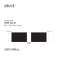
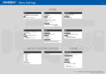
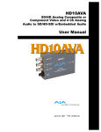
USER MANUAL
Check our knowledge base at
http://support.paralinx.net
TABLE OF CONTENTS
PARALINX TOMAHAWK
05
Safety Instructions
16
Receiver LED Status
06
Overview
17
Quick Start Guide
07
Package Contents
18
Remote control
08
HDMI Transmitter
19
Tomahawk Link Modes
10
3G-SDI Transmitter
20
Linking a transmitter to a single receiver
12
Transmitter LED Status
21
Linking a transmitter to multiple receivers
13
SLIDE & DIP Switches
22
Notes on Better Range
14
Receiver
23
Trouble Shooting
25
FAQ
26
Specifications
27
Tomahawk Accessories
3
4
IMPORTANT
NOTICE
IMPORTANT NOTICE
PARALINX TOMAHAWK
Paralinx reserves the right to make corrections, modifications, enhancements, improvements, and other
changes to its products and services at any time and
to discontinue any product or service without notice.
Customers should obtain the latest relevant information before placing orders and should verify that such
information is current and complete. All products are
sold subject to Paralinx’s terms and conditions of sale
supplied at the time of order acknowledgment.
Paralinx warrants performance of its hardware
products to the specifications applicable at the time of
sale in accordance with Paralinx’s standard warranty.
Testing and other quality control techniques are used
to the extent Paralinx deems necessary to support
this warranty. Except where mandated by government
requirements, testing of all parameters of each product is not necessarily performed.
Paralinx assumes no liability for applications assistance or customer product design. Customers are
responsible for their products and applications using
Paralinx components. To minimize the risks associated with customer products and applications, customers should provide adequate design and operating
safeguards.
Paralinx does not warrant or represent that any
license, either express or implied, is granted under
any Paralinx patent right, copyright, mask work right,
or other Paralinx intellectual property right relating
to any combination, machine, or process in which
Paralinx products or services are used. Information published by Paralinx regarding third-party
products or services does not constitute a license
from Paralinx to use such products or services or a
warranty or endorsement thereof. Use of such information may require a license from a third party under
the patents or other intellectual property of the third
party, or a license from Paralinx under the patents or
other intellectual property of Paralinx.
Reproduction of information in Paralinx manuals
or data sheets is permissible only if reproduction is
without alteration and is accompanied by all associated warranties, conditions, limitations, and notices.
Reproduction of this information with alteration is an
unfair and deceptive business practice. Paralinx is not
responsible or liable for such altered documentation.
Resale of Paralinx products or services with statements different from or beyond the parameters
stated by Paralinx for that product or service voids all
express and any implied warranties for the associated
Paralinx product or service and is an unfair and deceptive business practice. Paralinx is not responsible
or liable for any such statements.
All company and brand products and service names
are trademarks or registered trademarks of their
SAFETY INSTRUCTIONS
SAFETY
INSTRUCTIONS
PARALINX TOMAHAWK
When operating this equipment, read and follow all
the instructions in this manual.
Do not block the air ventilation openings.
Keep these instructions in a safe and accessible
place for future reference.
Unplug this apparatus during lightning storms or
when unused for long periods of time.
Do not use this apparatus near water.
Caution! Shock Hazard. Do not open the unit.
Clean only with a dry cloth.
Refer to qualified service personnel.
Do not install near any heat sources such as radiators, heat registers, stoves, or other apparatus
(including amplifiers) that produce heat.
Servicing is required when the apparatus has been
damaged in any way, such as power-supply cord or
plug is damaged, liquid has been spilled or objects
have fallen into the apparatus, the apparatus has
been exposed to rain or moisture, does not operate
normally, or has been dropped or damaged in any
way.
Use only accessories specified or recommended.
Do not defeat the polarized or grounding plug. A
polarized plug has two blades with one wider than
the other. A grounding-type plug has two blades and
a third grounding prong. The wide blade or the third
prong is provided for your safety. If the provided plug
does not fit into your outlet, consult an electrician
for replacement of your obsolete outlet. Caution! To
reduce the risk of electrical shock, grounding of the
center pin of this plug must be maintained.
Protect the power cord from being walked on or
pinched particularly at the plugs, convenience
receptacles, and the point where they exit from the
apparatus.
5
6
OVERVIEW
OVERVIEW
PARALINX TOMAHAWK
The Paralinx Tomahawk system is the worlds first light-weight
uncompressed ultra-long-range HD wireless system, capable
of sending ultra-low-latency full HD video with a range of up to
600m / 2000 feet
POWER INPUT WARNING!
The Tomahawk system accepts 7-17 volts DC maximum input
current! Subjecting the system to higher voltage will result in
damage or destruction!
PACKAGE CONTENTS
PACKAGE
CONTENTS
PARALINX TOMAHAWK
HDMI or HD-SDI wireless
video transmitter
1x 12v Power supply
2x 5dbi OMNI directional
antennas for Tx
HD-SDI wireless
video receiver
1x Remote Control & IR CABLE
1x BNC Or HDMI Video Cable
5x 2dbi OMNI directional
antennas for Rx
1x 18” PTap to Lemo-Style
power cable
Please verify the following
items are in the shipping box,
prior to installation of the
Tomahawk transmitter and
Tomahawk receiver:
1x USB to
miniUSB cable
7
8
TRANSMITTER
TRANSMITTER
SLIDE SWITCH
SETTINGS
PARALINX TOMAHAWK
HDMI TRANSMITTER
1
Dual RP-SMA
Type Antenna Connectors
2
Connection status LED
Indicates the wireless network status.
3
VIDEO status LED
indicates the video connection status.
4
Low battery LED
Indicates the battery voltage status.
5
Link button
For linking the transmitter to
additional receivers
6
Reset button
SINGLE-LINK MODE
S1
S2
7
USB Port
The USB port can be used for firmware
updates.
8
S1 Slide Switch
Left position: Single-link mode
Right position: Multicast mode
9
S2
Not used
10
HDMI Input port
11
7-17v LEMO power input connector
Pin 1 Hot, Pin 2 Ground
MULTI-LCAST MODE
S1
S2
HDMI TRANSMITTER
PARALINX TOMAHAWK
1
9
8
2
4
3
5
6
10
11
7
9
10
PARALINX TOMAHAWK
3G-SDI TRANSMITTER
3G-SDI
TRANSMITTER
1
Dual RP-SMA
Type Antenna Connectors
2
Connection status LED
Indicates the wireless network status.
3
VIDEO status LED
Indicates the video connection status.
4
Low battery LED
Indicates the battery voltage status.
5
Link button
For linking the transmitter to
additional receivers
6
Reset button
MULTICAST MODE
TRANSMITTER
SLIDE SWITCH
SETTING
S1
S2
7
USB Port
The USB port can be used for firmware
updates.
8
S1 Slide Switch
Left position: Single link mode
Right position: Multcast mode
9
S2
Not used
10
3G-SDI Pass-through connector
11
7-17v LEMO power input connector
12
Diagnostic LED
13
3G-SDI input connector
PARALINX TOMAHAWK
3G-SDI TRANSMITTER
1
9
6
8
5
10
12
4
3
13
2
11
7
11
12
TRANSMITTER LED STATUS
TRANSMITTER
LED STATUS
NETWORK LED CONNECTION
VIDEO LED CONNECTION
LOW BATTERY LED
PARALINX TOMAHAWK
Solid
When a connection to Rx is established
Slow blinking
Device is in listen mode
Normal blinking
During link setup mode.
Normal blinking
During registration (Reg button was pressed)
Fast blinking
(With Video LED)
System Error.
Solid
Video link established and locked in
Normal blinking
Video source is not supported
Fast blinking
(With Network LED)
System Error.
Solid
Low Battery,when voltage is less then 7v
PARALINX TOMAHAWK
SLIDE/DIP SWITCHES
13
TRANSMITTER
SLIDE SWITCH
SINGLE-LINK MODE
S1
S2
MULTICAST MODE
S1
S2
RECEIVER
DIP SWITCH
SINGLE-LINK MODE
v
1
1
2
3
4
2
3
4
14
RECEIVER
RECEIVER
DIP SWITCH
SETTINGS
RECEIVER
10
PARALINX TOMAHAWK
5x RP-SMA
Antenna Connectors
16
Link Button
17
Input Voltage connector 7-17v
11
Power LED
18
ON/OFF Switch
12
Network LED
19
IR input connector
20
HD-SDI output
13
Video LED
21
HD-SDI output
14
Diagnostic LED
22
Reset Button
23
Mini-USB for firmware updates
15
Receiver DIP Switches
DIP switch # 1, 2, & 3 should be UP
DIP switch # 4 UP = Single-link mode
DOWN = Multi-link mode
SINGLE-LINK MODE
MULTICAST MODE
1
1
2
3
4
2
3
4
RECEIVER
PARALINX TOMAHAWK
10
17
22
11
20
13
12
14
15
21
16
18
23
19
15
16
RECEIVER LED STATUS
PARALINX TOMAHAWK
RECEIVER LED
STATUS
VIDEO LED CONNECTION
POWER LED
Solid
Video link established and locked-in
Fast blinking
(With Network LED)
Video Source Error.
Solid
The LED is ON when the power is applied
and the ON/OFF switch is ON
QUICK START GUIDE
QUICK START
GUIDE
TRANSMITTER
RECEIVER
NOTES
For maximum range
*Note that high-output
wireless systems (EPV,
Radio Control Systems)
can interfere with the
Tomahawk & reduce the
overall range.
PARALINX TOMAHAWK
17
1
Turn on your video source.
2
Connect your Paralinx Tomahawk to a 12v power source via
the lemo input.
3
Connect your Tomahawk transmitter to the source camera using
a video cable.
4
For optimal results set the dual antennas in the form of
a “V” and maintain unobstructed line of sight between transmitter
and receiver.
5
Connect your Tomahawk Receiver to a monitor using an
HD-SDI cable.
6
Connect your Tomahawk Receiver to a 12v power source using the
lemo input, or integrated battery plate.
7
For optimal results antennas should be arranged in the form of an
open hand and maintain unobstructed line of site between transmitter and receiver.
Keep line of sight between the transmitter and the receiver.
Maintain proper air ventilation for transmitter and receiver.
Avoid placing any obstacles between transmitter
and the receiver.
If you lose signal bring the transmitter and receiver
closer together.
Position both transmitter and receiver in an upwards
position, for enhanced antenna performance.
If using multiple receivers, keep a minimum of 6 feet
between receiver units.
18
REMOTE CONTROL
REMOTE
CONTROL
REMOTE
CONTROL
HOTKEYS
PARALINX TOMAHAWK
1
MENU - Enter the main
menu
2
EXIT - Return to previous
menu
3
SOURCE [Select Video Source]
4
ARROWS -Operate for up,
down left and right directions on the menu screen
5
OK - Press to confirm
“ADD” hotkey button
Direct access for starting the registration process on the receiver.
“Delete” hotkey button
This hotkey button is open the “Remove Video Source” in the OSD menu
which allow the user to choose which device to remove.
Input Devices Key
This hotkey buttons “1, 2 or 3” keys will switch the receiver to work with
the first, second or third source, registered to the receiver, as appeared
on the registered sources list.
TOMAHAWK LINK MODES
TOMAHAWK
LINK MODES
Linking Tip:
Single-link mode enables DFS
(Dynamic Frequency Selection).
DFS allows the Tomahawk to
utilize more channels and to
automatically find the channel with the least amount of
interference.
The transmitter should be
kept within 150 feet of range
of the receiver until DFS is
activated (60 seconds).
This will help the Tomahawk
coexist better with other wireless systems in the area
PARALINX TOMAHAWK
19
The Paralinx Tomahawk supports the linking multiple receivers to a
single transmitter as well as the linking of multiple transmitters to a
single receiver. The following guide illustrates different modes and
options for linking transmitters and receivers:
SINGLE-LINK MODE: Offers the best practice for operating a maximum number of Tomahawk systems within the same enviroment.
Also allows for re-linking at longer distances.
transmitter slide switch
receiver DIP switch
MULTICAST MODE: Allows the linking of up to four Tomahawk
receivers to a single transmitter. Linking can only be established
within close proximity.
MULTICAST MODE
Transmitter slide switch
MULTICAST MODE
Receiver DIP switch
20
LINKING A TRANSMITTER TO A SINGLE RECEIVER
LINKING A
TRANSMITTER
TO A SINGLE
RECEIVER
If there is no transmitter
registered to the receiver, you
should see a menu on the monitor.
These modes are set by the toggle
switches.
PARALINX TOMAHAWK
1
*Connect an HD-SDI cable from the Paralinx Tomahawk receiver to the HD display.
2
Turn on the transmitter and receiver.
3
Use the remote control at the Paralinx Tomahawk receiver and Press the “Add” Hotkey button.
4
The message “Please Activate the Registration on Transmitter Unit” will appear on the monitor.
5
Pressing the registration button on the transmitter until the “Network” LED starts blinking.
6
Wait for the message of “Adding [Tx name] Press OK to continue or Exit to cancel”.
7
Press the “OK” button on the Remote control to confirm the new Paralinx Tomahawk transmitter.
8
Wait until the registration process is completed. The message of “ Adding [Tx name]…”and progress bar
will be shown during the process.
9
Connect the HD Source to the Paralinx Tomahawk transmitter.
10 Video should be displayed on your monitors..
NOTE
Once the registration process has started on the receiver, there is 30 Sec to start registration on the transmitter
side. If the registration process on the transmitter was
not started on time, re-start the registration process
by going back to step 4 listed above.
*The registration process can be done without HD source; the message will
notify you there is “no video source detected.”
LINKING A TRANSMITTER TO MULTIPLE RECEIVERS
LINKING A
TRANSMITTER
TO MULTIPLE
RECEIVERS
The Paralinx Tomahawk
transmitter has the ability to
connect up to 4 receivers at a time.
NOTE: Before Pairing, both Transmitter and
Receiver must be set to Single-Link Mode.
(see page 19)
1
PARALINX TOMAHAWK
8
Press OK to continue or Exit to cancel”.
Press the “OK” button on the IR Remote to
confirm the addition of the receiver.
There is a need to make sure the transmitter
is not transmitting video to other receivers,
so all other receivers which are registered
to the transmitter should be powered down
while registering an additional receiver.
9
2
Using HD-SDI cables connect each
Tomahawk receiver to a HD display.
11
3
Power on ONLY ONE transmitter and receiver AT A TIME.
In order to add additional receiver to the
transmitter, Power down all other Tomahawk receivers, except the new one.
12
Repeat steps 5 through 12 for each receiver.
4
Connect the IR Cable to your receiver. Press
the “Add” Hotkey button on the remote control while pointing the remote at the sensor
on the IR Cable (.
13
When all the receivers have been registered
to the transmitter power on all the receivers
one by one.
14
*Connect the video source to the Tomahawk
transmitter
15
The video should be displayed on all monitors.
5
6
7
The message “Please Activate the Registration on Transmitter Unit” will appear on the
monitor.
Press the registration button on the
transmitter until the “Network” LED starts
blinking.
Wait for the message of “Adding [Tx name]
10
Wait until the registration process is completed. A message of “ Adding [Tx name]…
”and progress bar will be displayed during
the process.
21
22
NOTES FOR
BETTER
RANGE
.
NOTES FOR BETTER RANGE
PARALINX TOMAHAWK
1. ALLOW THE SYSTEM TO ACTIVATE DFS WHILE THE TRANSMITTER IS WITHIN 50 FT OF THE RECEIVER.
WHEN STARTED, THE OSD WILL READ: “PLS. WAIT 60 SEC. ACQUIRING DFS FREQ.” AFTER 60 SECONDS
THE OSD WILL EITHER SAY “READY,” MEANING THE TOMAHAWK SYSTEM IS TRANSMITTING, OR, “PLS.
WAIT 60 SEC. ACQUIRING ALTERNATIVE FREQ,” MEANING THE TOMAHAWK IS SWITCHING TO A CHANNEL
WITH LESS INTERFERENCE.
PLEASE WAIT 60 SECONDS FOR DFS FREQUENCY. YOU SHOULD HAVE ALL OTHER WIRELESS SYSTEMS
ON AND WITHIN 50 FT OF THE RECEIVER UNTIL THIS PROCESS IS COMPLETE. THIS CYCLE SCANS FOR
INTERFERENCE FROM OTHER DEVICES, AND FINDS A CHANNEL WITH THE LEAST AMOUNT OF NOISE.
PLEASE NOTE THAT SOME HIGH-POWERED RADIO SYSTEMS, INCLUDING FLIGHT CONTROL, FPV, ETC.,
CAN ACT AS A JAMMER TO THE TOMAHAWK.
TRY TO AVOID USING 5 GHZ SYSTEMS WITHIN 6 FT OF THE TOMAHAWK TRANSMITTER OR RECEIVER.
SOME HIGH-POWERED 2.4 GHZ SYSTEMS MAY CAUSE INTERFERENCE AS WELL. PLEASE NOTE THAT
YOU SHOULD KEEP THE TOMAHAWK RECEIVER CASE CLEAR OF RF BLOCKING MATERIALS AS THE DFS
ANTENNA IS LOCATED INSIDE THE RECEIVER CASE.
2. MAKE SURE YOUR POWER SOURCE IS CAPABLE OF PROVIDING THE TOMAHAWK WITH 2A (RECEIVER) OR 1.5A (TRANSMITTER) IN ADDITION TO THE AMPERAGE NEEDED FOR OTHER DEVICES ON THE
SAME CIRCUIT.
3. THE ARROW-X DEFAULT ANTENNAS SHOULD BE SPLAYED ORTHOGONALLY FACING EACH OTHER.
THE TRANSMITTER ANTENNAS SHOULD FORM A “V” AND THE RECEIVER ANTENNAS SHOULD BE
ADJUSTED TO LOOK LIKE THE SPLAYED FINGERS ON A HAND.
4. USING CIRCULAR POLARIZED (CLOVER-LEAF) ANTENNAS ON THE TRANSMITTER WILL ALLOW
REFLECTED WAVES FROM THE EMITTER TO MAINTAIN THEIR POLARIZATION WHEN REFLECTING OFF
SURFACES IN THE ENVIRONMENT. THIS HELPS WITH PROPAGATION OF THE SIGNAL. IT IS BEST TO
USE TRANSMITTER AND RECEIVER ANTENNAS WITH MATCHING POLARIZATION.
TROUBLE SHOOTING
TROUBLE
SHOOTING
PARALINX TOMAHAWK
1. IF THE MONITOR DISPLAYS A BLACK SCREEN WITH A RED, FOUR-BAR SIGNAL ICON IN THE CORNER,
THE SIGNAL HAS BEEN LOST, AND THE SEARCH PROCESS MUST MANUALLY BE RESTARTED. THERE ARE
SEVERAL WAYS OF DOING THIS:
- THE RECEIVER MAY BE POWER CYCLED VIA THE ON/OFF SWITCH
- THE RECEIVER MAY BE POWER CYCLED VIA THE REMOTE (THE IR CABLE MUST BE PLUGGED INTO THE
RECEIVER):
.
- USING THE “GUEST” BUTTON ON THE SUPPLIED REMOTE: PRESS ONCE TO GO TO STANDBY, PRESS
ONCE MORE TO RESUME
- PRESS THE “MENU” BUTTON, SELECT “DISCONNECT WIRELESS LINK”, THEN RECONNECT EITHER BY
PRESSING THE
APPROPRIATE “INPUT DEVICES” HOTKEY, OR BY PRESSING THE “SOURCE” HOTKEY, AND SELECTING THE
APPROPRIATE INPUT SOURCE
2. IF THE RECEIVER AND TRANSMITTER ARE BOTH POWER-CYCLED, BUT ONLY A BLACK SCREEN
IS SHOWN, FIRST CHECK THAT YOU SOURCE IS OUTPUTTING SOMETHING OTHER THAN A BLACK
SCREEN, THEN UNPLUG THE SOURCE FROM THE TRANSMITTER AND RE-INSERT THE VIDEO SOURCE
CABLE.
3. THE TOMAHAWK SHOULD BE ABLE TO FIND A DFS FREQUENCY WITHIN 60 SECONDS IN NORMAL
CONDITIONS, BUT IT MAY TAKE LONGER IN AREAS WITH MORE INTERFERENCE. IF THIS PROCESS IS
NOT IDEAL, DFS CAN BE TURNED OFF BY SWITCHING BOTH TRANSMITTER AND RECEIVER TO MULTILINK MODE (SEE PAGE 19 OF INSTRUCTION MANUAL)
FOR ADDITIONAL INFORMATION AND SUPPORT VISIT OUR KNOWLEDGE BASE AT:
WWW.PARALINX.NET/HELP
23
24
TROUBLESHOOTING
(CONT’D)
.
TROUBLE SHOOTING CONTINUED
PARALINX TOMAHAWK
4. IF THE “SEARCHING” MESSAGE APPEARS ON THE OSD FOR AN EXTENDED PERIOD OF TIME WITHOUT
MAKING A LINK, PLEASE TRY THESE TROUBLESHOOTING PROCEDURES:
- A LINK WILL ONLY BE MADE IF THE TRANSMITTER IS IN RANGE OF THE RECEIVER. IT IS RECOMMENDED TO KEEP THE TRANSMITTER WITHIN 50 FT LINE-OF-SIGHT OF THE RECEIVER UNTIL A LINK
IS ESTABLISHED.
- MAKE SURE THAT ALL THE ANTENNAS ARE ATTACHED AND SECURED TO THE TOMAHAWK TRANSMITTERS AND RECEIVERS.
- YOU MAY BE IN AN ENVIRONMENT WITH HEAVY RF INTERFERENCE. MOVE TO A NEARBY LOCATION
THAT IS SHIELDED FROM OTHER RF SIGNALS (INSIDE A METAL OR CONCRETE STRUCTURE, BASEMENT, ETC.), AND START THE CONNECTION PROCESS OVER AGAIN.
FREQUENTLY ASKED QUESTIONS
FAQ
.
PARALINX TOMAHAWK
25
WHY DOES THE RECEIVER HAVE 5 ANTENNAS?
THE TOMAHAWK UTILIZES MIMO TECHNOLOGY. MIMO OFFERS SIGNIFICANT INCREASES IN DATA
THROUGHPUT AND LINK RANGE WITHOUT ADDITIONAL BANDWIDTH OR INCREASED TRANSMIT POWER.
IT ACHIEVES THIS GOAL BY SPREADING THE SAME TOTAL TRANSMIT POWER OVER THE ANTENNAS TO
ACHIEVE AN ARRAY GAIN THAT IMPROVES THE SPECTRAL EFFICIENCY (MORE BITS PER SECOND PER
HERTZ OF BANDWIDTH) AND/OR TO ACHIEVE A DIVERSITY GAIN THAT IMPROVES THE LINK RELIABILITY
(REDUCED FADING).
IF THE TOMAHAWK LOSES ITS SIGNAL, HOW LONG DOES IT TAKE TO REGAIN CONNECTION?
TYPICALLY, THE TOMAHAWK WILL RECONNECT WITHIN TEN SECONDS OF RETURNING WITHIN RANGE.
THIS TIME MAY BE AFFECTED BY RF INTERFERENCE IN THE SURROUNDING ENVIRONMENT.
IS THERE A TOMAHAWK RECEIVER WITH AN HDMI OUTPUT?
NOT AT THIS TIME, BUT AN ATOMOS CONNECT MAY BE DOCKED ONTO THE TOMAHAWK RECEIVER VIA AN
OPTIONAL SONY NP-F BATTERY PLATE.
HOW LONG DOES IT TAKE TO LINK THE SYSTEMS TOGETHER?
THE LINKING TIME BETWEEN A TOMAHAWK TRANSMITTER AND RECEIVER TYPICALLY TAKES LESS THAN
60 SECONDS, BUT MAY INCREASE IN AREAS WITH HEAVY RF INTERFERENCE. IT IS RECOMMENDED THAT
LINKING BE DONE IN AN ENVIRONMENT WITHOUT HEAVY RF INTERFERENCE.
ON WHAT FREQUENCY BAND DOES THE TOMAHAWK OPERATE?
THE TOMAHAWK OPERATES WITHIN THE LICENSE-FREE 5 GHZ BAND (5.1-5.8 GHZ). THE EXACT CHANNELS USED DEPENDS ON OPERATING MODE AND REGION.
26
SUPPORTED
FRAMERATES /
RESOLUTIONS*
*The Tomahawk system supports
Interlaced, Progressive, and Progressive Segmented Frame Signals
SPECIFICATIONS
PARALINX TOMAHAWK
1080P/50,720/50P
525I/59.94
1080P/60
625I/50I
1080/59.94I
1080/24P
1080/50I
1080/24PSF
1080/29.97P
1080/23.98PSF
1080/23.98P
1080/25PSF
720/59.94P
AUDIO
FORMATS
I2S, PCM, SPDIF, AC-3, DTS, DOLBY 5.1
FREQUENCIES
EU CHANNELS - 5.19 ~ 5.23 GHZ,
US CHANNELS - 5.19 ~ 5.23 GHZ AND 5.755~5.795 GHZ
DFS
FREQUENCIES
5.27 ~ 5.55 AND 5.67 GHZ
ARROW-X ACCESSORIES
OPTIONAL
ACCESSORIES
.
PARALINX TOMAHAWK
27
GO TO WWW.PARALINX.NET/STORE TO CHECK OUT ALL ACCESSORIES AND BUILD YOUR CUSTOMIZED KIT