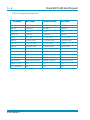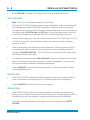
1
GE
Sensing
Druck ADTS 405
Air Data Test Systems
User Manual K114
Ps
Aim
Pt
Aim
DRUCK ADTS 405 HAND TERMINAL
ATEX COMPLIANT
CT WHEN
DO NOT DISCONNE
US AREA
IN THE HAZARDO
ENERGIZED
DRUCK ADTS 405 HAND TERMINAL
ATEX COMPLIANT
CT WHEN
DO NOT DISCONNE
US AREA
IN THE HAZARDO
ENERGIZED
1013. 25 mbar
1013. 25<
3199. 91 mbar
3200. 00
© General Electric Company. All rights reserved.
Druck ADTS 405
Air Data Test Systems
User Manual
K114
Ps
Aim
Pt
Aim
1013. 25 mbar
1013. 25<
3199. 91 mbar
3200. 00
DRUCK ADTS 405 HAND TERMINAL
ATEX COMPLIANT
CT WHEN
DO NOT DISCONNE
US AREA
IN THE HAZARDO
ENERGIZED
DRUCK ADTS 405 HAND TERMINAL
ATEX COMPLIANT
ECT WHEN
DO NOT DISCONN
US AREA
IN THE HAZARDO
ENERGIZED
K114 Issue No. 9
K114 Issue No. 9
Druck ADTS 405 User Manual
i
Introduction
This technical manual provides operating instructions for the Air Data Test System compatible
with the requirements of first line servicing.
Scope
This technical manual contains a brief description, operation and testing procedures for the
user of this equipment.
Safety
The manufacturer has designed this equipment to be safe when operated using the
procedures detailed in this manual. Do not use this equipment for any other purpose
than that stated.
This publication contains operating and safety instructions that must be followed to
make sure of safe operation and to maintain the equipment in a safe condition. The
safety instructions are either warnings or cautions issued to protect the user and the
equipment from injury or damage.
Use qualified* technicians and good engineering practice for all procedures in this
publication.
Pressure
Do not apply pressure greater the maximum safe working pressure to the equipment.
Toxic Materials
There are no known toxic materials used in this equipment.
Maintenance
The equipment must be maintained using the manufacturer’s procedures and should
be carried out by authorised service agents or the manufacturer’s service
departments.
Technical Advice
For technical advice contact the manufacturer or subsidiary.
*
A qualified technician must have the necessary technical knowledge, documentation,
special test equipment and tools to carry out the required work on this equipment.
CE
This product meets the essential protection requirements of the relevant EEC directives.
Further details of applied standards may be found in the product specification.
K114 Issue No. 9
ii
Associated Publications
This lists the Druck manuals and publications referenced in this manual.
Maintenance Manual
Air Data Test System ADTS 405
Calibration Manual
Air Data Test System ADTS 405
IEEE 488 OPT 2 Manual
Air Data Test System ADTS 405
SCPI IEEE 488 Manual
Air Data Test System ADTS 405
User Manual
Altimeter Encoder Option
User Manual
ARINC 429 Option
User Manual
Line Switching Unit LSU 100/101
User Manual
Line Switching Unit LSU 200
Operating and Communications Manual
Line Switching Unit LSU Series
TPM Programming and Communications Manual
Test Program Manager Version 4 for Windows
TPM User Manual
Test Program Manager Version 4 for Windows
K244
K199
K154
K157
K170
K185
K220
K222
K223
K230
K250
Symbols
This symbol, on the instrument, indicates that the user should refer to the user manual.
This symbol, on the instrument, indicates do not throw-away in domestic bin,
hazardous material, dispose correctly in accordance with local regulations.
This symbol, on the instrument , indicates d.c.
K114 Issue No. 9
CONTENTS
iii
Table of Contents
Preliminary pages
Introduction
............................................................................................................................................................ i
Scope
............................................................................................................................................................ i
Associated Publications ........................................................................................................................................................ ii
Symbols
............................................................................................................................................................ ii
Table of contents (this table) ............................................................................................................................................. iii
Abbreviations
............................................................................................................................................................ viii
Glossary
............................................................................................................................................................ ix
Returned Goods Procedure for Europe ......................................................................................................................... xi
Returned Materials Procedure for USA .......................................................................................................................... xii
Approved Service Agents ..................................................................................................................................................... xii
ATEX Certified ADTS Hand Terminal ................................................................................................................................ xiii
Pressure Units and Conversion Factors ........................................................................................................................ xiv
Section
page
1 DESCRIPTION
1.1
1.2
1.3
Introduction ................................................................................................................................................. 1-1
Operating Range and Performance ................................................................................................ 1-3
Operating Limits ........................................................................................................................................ 1-3
2 INSTALLATION
2.1
2.2
2.3
2.4
2.5
2.6
Packaging ..................................................................................................................................................... 2-1
Packaging for Storage and Transportation ................................................................................. 2-1
Electrical Connection .............................................................................................................................. 2-5
Pneumatic Pressure Connections ..................................................................................................... 2-7
Positioning of the ADTS 405 ................................................................................................................. 2-8
Positioning of the ADTS 405F .............................................................................................................. 2-9
3 OPERATION
3.1
3.2
3.3
3.4
3.5
3.6
3.7
3.8
3.9
3.10
3.11
3.12
3.13
3.14
Preparation .................................................................................................................................................. 3-1
Display Functions and Units of Measure ...................................................................................... 3-2
Quick Reference ......................................................................................................................................... 3-3
First Time Operators ................................................................................................................................ 3-4
Operation and Example Procedures ............................................................................................... 3-10
3.5.1 Checks Before Use .................................................................................................................... 3-10
3.5.2 Operating Procedures ............................................................................................................. 3-10
Power-up ....................................................................................................................................................... 3-10
Control or Measure Parameter .......................................................................................................... 3-11
Leak Testing the ADTS 405 ................................................................................................................... 3-12
Displays ......................................................................................................................................................... 3-15
Rate Timer Displays ................................................................................................................................. 3-17
Pt Only Display ........................................................................................................................................... 3-18
Changing the Display ............................................................................................................................. 3-18
Changing the Units .................................................................................................................................. 3-19
Limit Checking ............................................................................................................................................ 3-19
Aircraft System Protection ................................................................................................................... 3-21
Mach Test and Constant Mach .......................................................................................................... 3-21
K114 Issue No. 9
Druck ADTS 405 User Manual
iv
Table of Contents (contd)
Section
3.15
3.16
3.17
3.18
page
True Airspeed .............................................................................................................................................. 3-21
Airspeed Switch Test ............................................................................................................................... 3-22
Engine Pressure Ratio (EPR) ................................................................................................................. 3-23
Testing Aircraft Systems or UUT ....................................................................................................... 3-24
3.15.1 Go to Ground and Shut-Down ............................................................................................ 3-24
Options ........................................................................................................................................................... 3-25
SCPI IEEE 488 Option ............................................................................................................................... 3-25
Altimeter Encoder Option ..................................................................................................................... 3-25
ARINC 429 Option ..................................................................................................................................... 3-25
SETUP and CONFIGuration ................................................................................................................... 3-26
Quick Reference ......................................................................................................................................... 3-26
4 MAINTENANCE
4.1
4.2
4.3
4.4
Introduction ................................................................................................................................................. 4-1
Materials ........................................................................................................................................................ 4-2
Maintenance Tasks .................................................................................................................................. 4-3
Routine Maintenance .............................................................................................................................. 4-4
5 TESTING AND FAULT FINDING
5.1
5.2
5.3
5.4
5.5
5.6
5.7
5.8
Introduction ................................................................................................................................................. 5-1
Standard Serviceability Test ............................................................................................................... 5-2
Self-test Errors ............................................................................................................................................ 5-4
Venting after Over-pressure ............................................................................................................... 5-4
Fault Diagnosis .......................................................................................................................................... 5-5
Further Testing ........................................................................................................................................... 5-8
Test Environment and Preliminary Operations .......................................................... 5-8
Pressure Leak Check ............................................................................................................... 5-8
Vacuum Leak Check ................................................................................................................ 5-9
Controller Stability .................................................................................................................... 5-10
Testing an Option Facility ..................................................................................................................... 5-11
Testing the IEEE 488 Facility ................................................................................................................ 5-11
Configuring and Enabling the IEEE 488 Facility ......................................................................... 5-11
Programming a Test of the IEEE 488 Facility .............................................................................. 5-12
Connection of the IEEE 488 Facility ................................................................................................. 5-13
Testing the Altimeter Encoder Option ............................................................................................. 5-14
Configuring and Enabling the Altimeter Encoder Option ...................................................... 5-14
Optional cable (AAU-32) ......................................................................................................................... 5-15
Testing the ARINC 429 Option ............................................................................................................ 5-16
Configuring and Enabling the ARINC 429 Option ..................................................................... 5-16
Fault Finding ................................................................................................................................................ 5-17
5.8.1 Error Messages ........................................................................................................................... 5-17
5.8.2 Warning Messages ................................................................................................................... 5-18
6 REFERENCE and SPECIFICATION
6.1
6.2
Introduction ................................................................................................................................................. 6-1
Main Pressure Display ............................................................................................................................ 6-1
F1 - F4 ............................................................................................................................................. 6-1
ALT Ps .............................................................................................................................................. 6-2
K114 Issue No. 9
CONTENTS
v
Table of Contents (contd)
Section
6.3
page
SPEED Qc ....................................................................................................................................... 6-2
MACH Pt ......................................................................................................................................... 6-3
EPR .................................................................................................................................................... 6-4
ROC Ps RATE ................................................................................................................................ 6-4
RATE TIMER ................................................................................................................................... 6-4
HOLD ............................................................................................................................................... 6-5
RATE ................................................................................................................................................. 6-6
LEAK MEASURE/CONTROL ..................................................................................................... 6-6
GROUND ........................................................................................................................................ 6-7
PORT ................................................................................................................................................ 6-9
REMOTE .......................................................................................................................................... 6-9
PRINT ............................................................................................................................................... 6-9
EXECUTE TEST PROGRAM ...................................................................................................... 6-10
HELP ................................................................................................................................................. 6-12
or (nudge keys) .................................................................................................................. 6-12
0 to 9 ................................................................................................................................................ 6-12
-000 .................................................................................................................................................. 6-13
CLEAR/QUIT .................................................................................................................................. 6-13
ENTER .............................................................................................................................................. 6-14
CLEAR/QUIT + ENTER (ABORT) ............................................................................................................. 6-14
SET-UP ............................................................................................................................................................ 6-15
FULL SET-UP ................................................................................................................................................ 6-15
SETUP, [UNITS] ............................................................................................................................ 6-16
SETUP, [LIMITS] ........................................................................................................................... 6-16
SETUP, [OSC] ................................................................................................................................ 6-17
SETUP, [MORE], [CONTROL],[Ps Pt DUAL] ....................................................................... 6-17
SETUP, [MORE], [DISPLAYS/OPTIONS],[DISPLAY TYPE] ............................................. 6-18
SET-UP, [MORE], [DISPLAYS/OPTIONS],[OPTIONS] ...................................................... 6-20
SETUP, [MORE], [CLOSE OUTPUT VALVES] ...................................................................... 6-20
SETUP, [MORE], [OPEN OUTPUT VALVES] ....................................................................... 6-20
SET-UP, [MORE], [SYSTEM SELF TEST] ............................................................................... 6-20
SET-UP, ALT .................................................................................................................................. 6-21
SET-UP, SPEED [AUTO ZERO] ................................................................................................ 6-21
SET-UP, SPEED [CAS/TAS] ...................................................................................................... 6-21
SET-UP, SPEED [Pt TEMPERATURE] .................................................................................... 6-23
SET-UP, MACH ............................................................................................................................. 6-23
SET-UP, RATE TIMER ................................................................................................................................. 6-23
SET-UP, RATE ............................................................................................................................... 6-23
SET-UP, LEAK MEASURE CONTROL, [AUTO LEAK] ....................................................... 6-24
SET-UP, LEAK MEASURE CONTROL, [AUTO LIMIT] ...................................................... 6-24
SET-UP, GROUND ....................................................................................................................... 6-24
SET-UP, PORT ............................................................................................................................... 6-24
SET-UP, PRINT,[DATE/TIME] ................................................................................................... 6-24
SET-UP, EXECUTE TEST PROGRAM ..................................................................................... 6-24
SET-UP, HELP ............................................................................................................................... 6-25
SET-UP, or (nudge keys) ................................................................................................ 6-25
K114 Issue No. 9
Druck ADTS 405 User Manual
vi
Table of Contents (contd)
Section
page
MINIMUM SET-UP
6.4
............................................................................................................................................................ 6-26
SETUP, [UNITS], [AERO] ........................................................................................................... 6-26
SETUP, [UNITS], [PRESS] .......................................................................................................... 6-26
SETUP, [LIMITS] ........................................................................................................................... 6-26
SETUP, ALT/Ps .............................................................................................................................. 6-27
SETUP, PORT ................................................................................................................................. 6-27
SETUP, HELP ................................................................................................................................. 6-27
CONFIGURATION ....................................................................................................................................... 6-28
Procedure ...................................................................................................................................... 6-28
Functions ....................................................................................................................................... 6-28
CONFIG,[UNITS] .......................................................................................................................... 6-29
CONFIG, [LIMITS],[EDIT LIMITS],[EDIT EXISTING] .......................................................... 6-29
NAME ............................................................................................................................................... 6-30
MIN ALT,MAX ALT, MIN CAS, MAX CAS ............................................................................. 6-30
MAX MACH .................................................................................................................................... 6-30
MAX ROC, MAX RATE CAS ....................................................................................................... 6-30
MIN Ps, MAX Ps, MIN Qc, MAX Qc ....................................................................................... 6-30
MAX RATE Ps, MAX RATE Qc .................................................................................................. 6-30
ARINC LIMITS ............................................................................................................................... 6-30
ALTITUDE CORRECTION .......................................................................................................... 6-31
SAVING LIMITS ............................................................................................................................. 6-31
CONFIG, [LIMITS],[EDIT LIMITS],[MAX LIMITS] ................................................................ 6-32
CONFIG, [LIMITS],[EDIT LIMITS],[EDIT NEW] ................................................................... 6-32
CONFIG, [LIMITS],[CLEAR LIMITS] ........................................................................................ 6-32
CONFIG, [LIMITS],[LOCK AIRCRAFT] ................................................................................... 6-32
CONFIG, [LIMITS],[DEFAULT AIRCRAFT] ........................................................................... 6-32
CONFIG, [MORE],[CONTROL],[CONTROL MODE] .......................................................... 6-32
CONFIG, [MORE],[CONTROL],[CONTROL LOCK] ........................................................... 6-32
CONFIG, [MORE],[DISPLAY/OPTIONS],[DISPLAY TYPE] .............................................. 6-32
CONFIG, [MORE],[DISPLAY/OPTIONS],[OPTIONS] ........................................................ 6-32
CONFIG, [MORE],[DATE/FORMAT] ....................................................................................... 6-32
CONFIG, [MORE],[SETUP MODE] .......................................................................................... 6-33
FULL ................................................................................................................................................. 6-33
MINIMUM ....................................................................................................................................... 6-33
OFF ................................................................................................................................................... 6-33
CONFIG, SPEED,[AUTO ZERO] ............................................................................................... 6-33
CONFIG, SPEED,[CAS/TAS] ..................................................................................................... 6-33
CONFIG, SPEED,[Pt TEMPERATURE] ................................................................................... 6-33
CONFIG, RATE TIMER ................................................................................................................ 6-33
CONFIG, RATE .............................................................................................................................. 6-33
CONFIG, LEAK MEASURE, [AUTO LEAK ON/OFF] ......................................................... 6-33
CONFIG, LEAK MEASURE, [AUTO LEAK LOCK] .............................................................................. 6-33
CONFIG, LEAK MEASURE, [AUTO LIMIT ON/OFF] ......................................................................... 6-33
CONFIG, LEAK MEASURE, [AUTO LIMIT LOCK] .............................................................................. 6-33
CONFIG, GROUND ..................................................................................................................................... 6-33
K114 Issue No. 9
vii
Table of Contents (contd)
Section
page
CONFIG, PORT ............................................................................................................................. 6-34
CONFIG, REMOTE ....................................................................................................................... 6-34
CONFIG, ETP,[AUTO RUN] ....................................................................................................... 6-34
CONFIG, ETP,[ERASE PROGRAMS] ...................................................................................... 6-34
CONFIG, ETP,[RESULT] ............................................................................................................. 6-34
CONFIG, or (nudge keys) ............................................................................................... 6-34
CONFIG, 000 ................................................................................................................................................ 6-34
Specification ................................................................................................................................................ 6-35
Zone 2 Hazardous Area Definition ................................................................................................... 6-42
6.5
List of Illustrations
Figure
Figure 1-1
Figure 1-2
Figure 2-1
Figure 2-2
Figure 2-3
Figure 2-4
Figure 2-5
Figure 2-6
Figure 3-1
Figure 3-2
Figure 3-3
Figure 3-4
Figure 3-5
Figure 3-6
Figure 3-7
Figure 3-8
Figure 3-9
Figure 5-1
Figure 6-1
Figure 6-2
Figure 6-3
page
ADTS 405 General View .......................................................................................................................... 1-2
ADTS 405F General View ....................................................................................................................... 1-2
Equipment and Parts .............................................................................................................................. 2-3
ADTS 405 Altitude Reference .............................................................................................................. 2-8
ADTS 405F Altitude Reference ............................................................................................................ 2-9
ADTS 405 General View .......................................................................................................................... 2-10
ADTS 405 Rear Panel View ................................................................................................................... 2-11
ADTS 405F General View ....................................................................................................................... 2-12
Front Panel ................................................................................................................................................... 3-2
Main Pressure Display (Leak Measure Mode) .............................................................................. 3-12
Main Pressure Display (Control Mode) ............................................................................................ 3-13
Single Display ............................................................................................................................................. 3-15
Dual Display ................................................................................................................................................ 3-16
Triple Display .............................................................................................................................................. 3-16
Rate Timer Display Aeronautical Units .......................................................................................... 3-17
Rate Timer Display Pressure Units ................................................................................................... 3-17
Pt Only Display ........................................................................................................................................... 3-18
Fault Finding Chart .................................................................................................................................. 5-6
Altitude Correction Rack Mounting .................................................................................................. 6-22
Altitude Correction On-aircraft .......................................................................................................... 6-22
ARINC 565 Operating Limits ................................................................................................................ 6-31
List of Tables
Table
2-1
4-1
4-2
4-3
5-1
5-2
5-3
page
Parts List ........................................................................................................................................................ 2-4
Maintenance Chart .................................................................................................................................. 4-1
Materials List ............................................................................................................................................... 4-2
Tool and Test Equipment Requirements ....................................................................................... 4-2
Fault Finding ................................................................................................................................................ 5-7
Error Messages .......................................................................................................................................... 5-17
Warning Messages ................................................................................................................................... 5-18
K114 Issue No. 9
Druck ADTS 405 User Manual
viii
Abbreviations
The following abbreviations are used in this manual; the abbreviations are the same in the singular and plural.
A
abs
a.c.
ALT
ATEX
CAS
d.c.
e.g.
EOC
EPR
EPROM
etc.
Fig.
ft
g
Hg
Hz
IAS
i.e.
IEEE 488
in
kg
LED
m
mA
max
mbar
min
mm
mV
No.
N.m.
Para.
Ps
psi
Pt
Qc
QFE
QNH
ROC
SCPI
TAS
TE
V
Vc
Vt
+ve
-ve
°C
°F
K114 Issue No. 9
Ampere
Absolute
Alternating current
Altitude
Equipment for Use in Potentially Explosive Atmosheres
Calibrated airspeed
Direct current
For example
End of conversion
Engine pressure ratio
Electrically programmable read only memory
And so on
Figure
Foot
Gauge
Mercury
Hertz
Indicated airspeed
That is
Institute of Electrical and Electronic Engineers standard 488 data
Inch
Kilogram
Light emitting diode
Metre
Milliampere
Maximum
Millibar
Minute or minimum
Millimetre
Millivolts
Number
Newton metre
Paragraph
Static pressure
Pounds per square inch
Total pressure
Differential pressure Ps-Pt
Local atmospheric pressure
Barometric pressure at sea level
Rate of climb
Standard commands for programmable instruments
True airspeed
Test equipment
Volts
Calibrated velocity
True velocity
Positive
Negative
Degrees Celsius
Degrees Fahrenheit
Glossary
ix
Glossary
Terminology
The terminology used in this manual is specific and individual interpretation must not be
introduced. The terms are defined as follows:
Adjust
To bring to a more satisfactory state; to manipulate controls, levers, linkages,
etc. to return equipment from an out-of-tolerance condition to an in-tolerance
condition.
Align
To bring into line; to line up; to bring into precise adjustment, correct relative
position or coincidence.
Assemble:
To fit and secure together the several parts of; to make or form by combining
parts.
Calibrate:
To determine accuracy, deviation or variation by special measurement or by
comparison with a standard.
Check:
Make a comparison of a measure of time, pressure, temperature, resistance,
dimension or other quality with a known figure for that measurement.
Disconnect:
To detach the connection between; to separate keyed or matched equipment
parts.
Dismantle:
To take apart to the level of the next smaller unit or down to all removable parts.
Examine:
To perform a critical visual observation or check for specific conditions; to test the
condition of.
Fit:
Correctly attach one item to another.
Inspect:
Review the work carried out by Specialists to make sure it has been performed
satisfactorily.
Install:
To perform operations necessary to properly fit an equipment unit into the next
larger assembly or system.
Maintain:
To hold or keep in any particular state or condition especially in a state of
efficiency or validity.
Make sure:
To confirm that a proper condition exists; to find out with certainty.
Operate:
Make sure that an item or system functions correctly as far as possible without
the use of test equipment or reference to measurement.
Power-up:
To perform operations necessary to switch on a system ready for use.
K114 Issue No. 9
Druck ADTS 405 User Manual
Power-down: To perform operations necessary to safely switch off a system after use.
Readjust:
To adjust again; to move back to a specified condition; to bring back to an
in-tolerance condition.
Reconnect:
To rejoin or refasten that which has been separated.
Refit:
Fit an item which has previously been removed.
Remove:
To perform operations necessary to take an equipment unit out of the next larger
assembly or system. To take off or eliminate. To take or move away.
Repair:
To restore damaged, worn out or malfunctioning equipment to a serviceable,
usable or operable condition.
Replace:
Remove an item and fit a new or a serviced item.
Reset:
To put back into a required position, adjustment or condition.
Service:
To perform such operations as cleaning, lubricating and replenishing to prepare for
use.
Test:
Ascertain by using the appropriate test equipment that a component or system
functions correctly.
K114 Issue No. 9
x
xi
Returned Goods Procedure
for Europe
Should the unit become unserviceable and require repair it can be returned to the Druck
Service Department.
Please contact our Service Department, either by 'phone, fax or e-mail to obtain a Returned
Goods Authorization (RGA) number, providing the following information:
Product (i.e. ADTS 405)
Pressure medium (i.e. air, nitrogen)
Serial number
Details of defect/work to be undertaken
Operating conditions
Safety Precautions
You must also tell us if the product has been in contact with anything hazardous or toxic and
the relevant COSH references and precautions to be taken when handling.
Important notice
Service by unauthorized sources will affect the warranty and may not guarantee further
performance.
K114 Issue No. 9
xii
Returned Material Procedure
for USA
Should the equipment become unserviceable it can be returned to the Druck Service
Department.
Please contact our Service Department, either by 'phone, fax or e-mail to obtain a Returned
Material Authorization (RMA) number, providing the following information:
Product (i.e. ADTS 405)
Pressure medium (i.e. air, nitrogen)
Serial number
Details of defect/work to be undertaken
Operating conditions
Safety Precautions
You must also tell us if the product has been in contact with anything hazardous or toxic and,
the relevant MSDS references and precautions to be taken when handling.
Important notice
Service by unauthorized sources will affect the warranty and may not guarantee further
performance.
Approved Service Agents
For the list of service centres visit our web site:
www.gesensing.com
K114 Issue No. 9
xiii
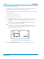
ATEX Certified ADTS Hand Terminal
CONDITIONS OF USE
The ATEX certified ADTS hand terminal supplied with the ADTS 405 can be used in zone 2
hazardous areas in accordance with the ATEX certification document and schedule.
ATEX Certificate of Conformity
No. Baseefa05ATEX0192
BASEEFA being an Approved Certification Body, in accordance with Article 14 of the Council
Directive of the European Communities of 18th December, 1975 (76/117/EEC) certifies that
the apparatus has been found to comply with harmonised European Standards:
EN 60079-15: 2003
and has successfully met the examination and test requirements recorded in confidential
report number:
05(C)0154 (Baseefa) dated 12th October 2005
NOTE: Refer to pages 2/2 of the Certificate of conformity for electrical connection parameters.
Rated Voltage = 32Vdc.
Marking detail:
ADTS Hand Terminal
Baseefa05ATEX0192
II 3G IP54
Baseefa05ATEX0192 (EC type examination certificate number)
EEx nA nL IIC T4 (-25°C <Tamb <=55°C)
Druck, LE6 0FH, UK
6 - 32V
Power
3W Max
SPECIAL CONDITION OF USE
•
•
•
The power supplies must be isolated when connecting the ADTS hand terminal in the
hazardous area.
The ADTS hand terminal must not be disconnected when energized in the hazardous
area.
The ADTS hand terminal is a non-serviceable component. If the ADTS hand terminal
becomes unserviceable it can only be replaced by another ATEX compliant hand
terminal.
K114 Issue No. 9
xiv
Pressure units and conversion factors
Pressure unit
Factor (Pascals)
Pressure unit
Factor (Pascals)
bar
100000
lbf/ft2
47.8803
lbf/in2 (psi)
6894.76
inHg
3386.39
mH2O
9806.65
inH2O
[1]
249.089
mbar
100
ftH2O
[1]
2989.07
kgf/cm2
98066.5
atm
101325.0
kgf/m2
9.80665
pdl/ft2
1.48816
mmHg
133.322
dyn/cm2
0.1
cmHg
1333.22
hbar
10000000
mHg
133322.0
tonf/ft2 (UK)
107252.0
mm/H2O
[1]
9.80665
tonf/in2 (UK)
15444300
cm/H2O
[1]
98.0665
inH2O (USA) [2]
248.64135
N/m2
1
ftH2O (USA) [2]
2983.6983
hPa
100
kp/mm2
9806650
2
kPa
1000
kp/cm
98066.5
MPa
1000000
kp/m2
9.80665
torr
133.322
Table of pressure units and conversion factors
Unit Conversion
To convert FROM pressure VALUE 1 in pressure UNITS 1
TO pressure VALUE 2 in pressure UNITS 2, calculate as follows:
VALUE 2
=
VALUE 1 x FACTOR 1
FACTOR 2
Note
The conversion factor for pressure units referenced [1] are calculated for a water temperature of 4°C.
Pressure units referenced [2] are calculated for a water temperature of 68°F these units are normally
used in the USA.
K114 Issue No. 9
Description
1-1
1
DESCRIPTION
1.1
Introduction
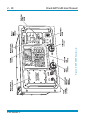
There are two versions of the ADTS 405, a 19", 6U high (10½”) rack-mounted unit and a
flight line unit.
The ADTS 405 is a rack-mounted system and, with external pressure and vacuum supplies
connected, provides measurement and control for leak checks, calibration accuracy
checks and functional tests of air data instruments, components and systems.
The ADTS 405F is a self-contained flight-line air data test system providing complete
pressure and vacuum measuring and control for on-aircraft sense and leak testing,
calibration accuracy checks and functional tests of air data instruments, components and
systems. The unit comprises an electronics rack and pump rack enclosed in a high density,
polyethylene case.
The ADTS 405 displays and operates in either units of pressure measurement or aeronautical
units. In the control mode, the rate that the pressures change towards new set-points can
be controlled in true aeronautical rate units.
There are two independent pneumatic channels connect to the aircraft or instrument
systems, one for static and one for pitot. They can be operated as measure only channels
with leak testing facility or each can be control channels producing true pressure
conditions for altitude and airspeed.
To protect sensitive instruments and equipment a `ground' facility automatically and
safely controls both channels to atmospheric pressure at the previously entered rates of
change and then informs the operator when both channels are safely at `ground'.
The operator interface is either an ATEX certified hand terminal connected to the front
panel or the key pad and display on the front panel. Both provide information and control
selections for the user through the keys and display. The unit can also be controlled
remotely using the IEEE 488 communications interface. The front panel contains the
operate switch and a mimic panel with LED indicators showing the operation of the
solenoid-operated pneumatic valves.
The pump rack, on the ADTS 405F, produces pressure and vacuum supplies for the
electronics rack and for external services. Located on the front panel, the external
connectors provide for external pressure and vacuum supplies (EXT PRESSURE and EXT
VACUUM) and an auxiliary static (vacuum) output (AUX). The rack is cooled by a fan located
under a protective cover on the front panel. The power supply connection for the ADTS
405F is located on the front panel.
K114 Issue No. 9
1
1-2
Druck ADTS 405 User Manual
Ps
Aim
Pt
Aim
1013. 25 mbar
1013. 25<
3199. 91 mbar
3200. 00
DRUCK ADTS 405 HAND TERMINAL
ATEX COMPLIANT
NECT WHEN
DO NOT DISCON
OUS AREA
IN THE HAZARD
ENERGIZED
FIGURE 1-1 ADTS 405 GENERAL VIEW
DRUCK ADTS 405 HAND TERMINAL
ATEX COMPLIANT
NECT WHEN
DO NOT DISCON
OUS AREA
IN THE HAZARD
ENERGIZED
FIGURE 1-2 ADTS 405F GENERAL VIEW
K114 Issue No. 9
Description
1-3
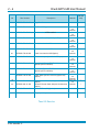
1.2
Operating Range and Performance
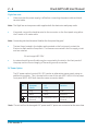
The ADTS 405 is supplied in one of two full-scale ranges (850 knots or 1000 knots) for
measurement and control of the pitot pressure channel.
Operating limits are set, pre-defined tabular limits known as STANDARD, CIVIL and MAX
these can be selected through the SETUP menu (see Reference section 6). Operators
may also configure the display to aeronautical or pressure units but should be aware
that when units of pressure are selected, wider full-scale pressure limits will be enabled
for some parameters.
1.3
Operating Limits
The following sets of operating limits are supplied with the ADTS 405.
850 knot range operating limits
P a ra m e te r
Max Limits
S tan d ard limits
Civil limits
Min Alt
-3,000 ft
-2,000 ft
-1,000 ft
Max Alt
105,000 ft
80,000 ft
50,000 ft
Min CAS
-100 kts
0.0 kts
0 kts
Max CAS
850 kts
850 kts
450 kts
Min Ps
3.0 mbar
27.615 mbar
115.972 mbar
Max Ps
1355.00 mbar
1088.657 mbar
1050.406 mbar
Min Qc
-1,352.00 mbar
0.0 mbar
0 mbar
Max Qc
1,700.00 mbar
1688.00 mbar
368.01 mbar
Max Mach
12.35
2.5
1
Max ROC
100,000 ft/min
9,000 ft/min
6,000 ft/min
Max Rate CAS
2,000 kts/min
600 kts/min
600 kts/min
Max Rate Ps
10,000.00 mbar/min
200.00 mbar/min
100.00 mbar/min
Max Rate Qc
10,000.00 mbar/min
200.00 mbar/min
100.00 mbar/min
ARINC Limits
OFF
OFF
OFF
Alt Correction
0 ft
0 ft
0 ft
K114 Issue No. 9
1
1-4
Druck ADTS 405 User Manual
1000 knot range operating limits
P a ra m e te r
Max Limits
S tan d ard limits
Civil limits
Min Alt
-3,000 ft
-3,000 ft
-1,000 ft
Max Alt
105,000 ft
80,000 ft
50,000 ft
Min CAS
-100 kts
0 kts
0 kts
Max CAS
1,000 kts
1,000 kts
450 kts
Min Ps
3.0 mbar
27.615 mbar
115.972 mbar
Max Ps
1355.00 mbar
1,128.029 mbar
1050.406 mbar
Min Qc
-1,352.00 mbar
-16.303 mbar
0 mbar
Max Qc
2,500.00 mbar
2,490.50 mbar
368.01 mbar
Max Mach
14.97
5
1
Max ROC
100,000 ft/min
15,000 ft/min
6,000 ft/min
Max Rate CAS
2,000 kts/min
700 kts/min
600 kts/min
Max Rate Ps
10,000.00 mbar/min
200.00 mbar/min
100.00 mbar/min
Max Rate Qc
10,000.00 mbar/min
200.00 mbar/min
100.00 mbar/min
ARINC Limits
OFF
OFF
OFF
ALT Correction
0 ft
0 ft
0 ft
K114 Issue No. 9
Installation
2-1
2
INSTALLATION
2.1
Packaging
On receipt of the ADTS 405 check the contents of the packaging against the following
lists:
Packaging List - ADTS 405F
Packaging List - ADTS 405
i)
ii)
iii)
iv)
v)
vi)
vii)
viii)
ix)
x)
i)
ii)
iii)
iv)
v)
vi)
vii)
viii)
ix)
Flight line ADTS 405F
Accessory bag
Power supply cable
Hand terminal
Hand terminal cable - 2 m
Hand terminal cable - 18 m
Output, hose, 2.5m, red, AN6 - open
Output, hose, 2.5m, blue, AN4 - open
User Manual (this publication)
Spare fuses (2 off)
Rack ADTS 405
Power supply cable
User Manual (this publication)
Output, hose, 2.5m, red, AN6 - open
Output, hose, 2.5m, blue, AN4 - open
Input, hose, 2.5m, green, AN6 - open
Input, hose, 2.5m, yellow, AN4 - open
Spare fuses (2 off)
Plug, expansion port
2.2
Packaging for Storage or Transportation
To store the unit or to return the unit for calibration or repair carry out the following
procedures:
1.
Pack the unit as detailed in the following procedure.
2.
To return the unit for calibration or repair complete the return goods procedure
as detailed in the preliminary pages.
K114 Issue No. 9
2
2-2
Druck ADTS 405 User Manual
Procedure
The unit should be at zero/ambient pressure. Disconnect the hose assemblies and
stow in the shoulder bag.
Switch OFF and disconnect from the electrical power supply. Disconnect the
power supply cable and the hand terminal cable. Disconnect the hand terminal
cable from the hand terminal.
Stow the power supply cable, hand terminal cable and the hand terminal in the
ADTS 405F lid. For ADTS 405 rack units these items should be placed in a sealed
polythene bag.
Fit the lid to the unit.
If available, use the original packing material. When using packing materials other
than the original, proceed as follows.
Wrap unit in polyethylene sheeting.
Select a double-wall cardboard container. Inside dimensions must be at least
15 cm greater than the equipment. The carton must meet test strength
requirements of >125 kg.
Protect all sides with shock-absorbing material to prevent equipment movement
within the container.
Seal carton with approved sealing tape.
Mark carton “FRAGILE” on all sides, top, and bottom of shipping container.
Environment
The following conditions apply for both shipping and storage:
Temperature Range -40° to +70°C (-40° to +158°F)
Altitude ......................... Up to 15,000 feet (4,570 metres)
K114 Issue No. 9
Installation
2-3
1
3
2
DRUCK ADTS 405 HAND TERMINAL
ATEX COMPLIANT
NECT WHEN
DO NOT DISCON
DOUS AREA
IN THE HAZAR
ENERGIZED
4
13
8
9
2
11a
2m
5
10
18m
6
12
FIGURE 2.1 EQUIPMENT AND PARTS
K114 Issue No. 9
2-4
No
Druck ADTS 405 User Manual
Par t Num ber
Descr i pt i on
Used On
Qt y per
assy
1
ADTS405- 1728- 39- M0
Bag, Shoulder
ADTS 405F
1
2
ADTS405- 1728- 36- M0
Kit , Fuse/ O- Ring
1
3
ADTS405- 1728- 37- M1
Hand t erminal, ATEX certified
4
ADTS405- 1728- 47- M0
Cable, AC Power, 5M (260V Open End)
5
ADTS405- 1728- 28- M0
Cable, Hand t erminal 2M
6a
ADTS405- 1728- 27- M0
Cable, Hand t erminal 18M
6b*
ADTS405- 1728- 29- M0
Cable, Hand t erminal 30M (Opt ion)
ADTS 405F
and
ADTS 405
ADTS 405F
and
ADTS 405
ADTS 405F
and
ADTS 405
ADTS 405F
and
ADTS 405
ADTS 405F
and
ADTS 405
7*
ADTS405- 1729- 52- M0
Kit , hose adapt or (2 x 2.5M AN ST/ Open)
ADTS 405F
and
ADTS 405
1
8
ADTS405- 1729- 61- M0
Hose, St at ic (Ps), red, ST/ OPN, AN6
(Special opt ions available)
ADTS 405F
and
ADTS 405
1
9
ADTS405- 1729- 62- M0
Hose, Pit ot (Pt ), blue, ST/ OPN, AN4
(Special opt ions available)
ADTS 405F
and
ADTS 405
1
10
ADTS405- 1728- 34- M0
Cable, ARINC (Circular Connect or) (Open End)
(Opt ion)
1
11a
ADTS405- 1728- 35- M0
11b*
ADTS405- 1891- 61- M0
12
ADTS405- 1728- 48- M0
Cable, Alt imet er Encoder, 6M (Open End)
(Opt ion)
Alt imet er Encoder Cable, 6M (AAU- 32 alt imet ers)
(Opt ion)
Cable, DC Power, 5M (Opt ion)
ADTS 405F
and
ADTS 405
ADTS 405F
and
ADTS 405
ADTS 405F
1
13
ADTS405- 1891- 22- M0
Plug, expansion port
ADTS 405
1
TABLE 2-1 PARTS LIST
K114 Issue No. 9
1
1
1
1
1
1
1
Installation
2.3
2-5
Electrical Connection
WARNINGS: 1
VOLTAGES IN EXCESS OF 30 VOLTS (RMS) AC OR 50VOLTS DC,
IN CERTAIN CIRCUMSTANCES, CAN BE LETHAL. CARE MUST BE TAKEN
WHEN WORKING ON LIVE, EXPOSED CONDUCTORS.
2
DO NOT DISCONNECT THE HAND TERMINAL WHEN ENERGIZED IN THE
HAZARDOUS AREA.
Power Supply Connection
The unit must be connected to the correct electrical power supply as stated, adjacent
to the power connector.
CAUTIONS:
1
2
THE SUPPLY MUST PROVIDE CONNECTION TO A PROTECTIVE GROUND TERMINAL. THE UNIT
MUST , AT ALL TIMES, BE CONNECTED TO THE SUPPLY EARTH (GROUND ).
THE POWER SUPPLY CABLE AND CONNECTOR MUST BE CORRECTLY RATED FOR THE POWER
SUPPLY.
Note: The ADTS 405 is normally supplied with an approved power supply cable
for use in the country of delivery. This can limit the maximum supply
voltage that can be safely used.
e.g. a NEMA 5-15P terminated cable, for use in the U.S.A., is approved for a
maximum of 125 V ac; it must be replaced for a higher supply voltage.
Pin
European
Colour
U.S.
Color
Function
1
Brown
Black
Live
4
Blue
White
Neutral
Centre
Green/Yellow
Green
Protective Earth
(Ground)
2
ADTS 405 rack mounted units
Make sure that the power supply is off before connecting the power cable .
If required, connect the hand terminal to the connector using either the 2 metre or 18
metre cable.
Note: Connecting the hand terminal disables the front panel key-pad.
Fit the expansion port plug (item 13, Table 2-1) to the rear panel expansion port.
Note: For units used with the Druck PV 103 Pump Unit connect the expansion cable, supplied
with the PV 103, to the expansion port.
K114 Issue No. 9
2-6
Druck ADTS 405 User Manual
Flight line units
Make sure that the power supply is off before connecting the power cable and hand
terminal cable.
Note: The flight line version power cable supplies both the electronics and pump racks.
If required, connect the hand terminal to the connector on the front panel using either
the 2 metre or 18 metre cable.
Note: Connecting the hand terminal disables the front panel key-pad.
The two fuses, located in the holders and mounted on the front panel, protect the
Electronics Rack and the Pump Rack. The fuses are connected in the live supply circuit
and are rated at:
5A anti-surge HBC 250V
An external earth (ground) cable may be connected to the stud on the front panel of
the pump rack to ensure integrity of the earth (ground) connection.
DC Power Option
The DC power option (nominal 28 V DC), can be an alternative power supply using an
additional connector. This is located on the rear of the rack (ADTS 405) or on the pump
front panel (ADTS 405F) both have the same connector details.
Pin
European
Colour
U.S.
Color
Function
1
Grey
Gray
+28V
2
White
White
0V Return
Protective Earth
(Ground)
Protective Ground
Protective Earth
(Ground)
Note: The unit will not be damaged if AC power and DC power are connected at the same time.
K114 Issue No. 9
Installation
2.4
2-7
Pneumatic Pressure Connections
ADTS 405 rack-mounted unit
Static (Ps)
............................................................................................................................ AN-6 37° flare
Pitot (Pt)
............................................................................................................................ AN-4 37° flare
Pressure supply ....................................................................................................................... AN-4 37° flare
Vacuum supply ........................................................................................................................ AN-6 37° flare
Connect pressure and vacuum supplies to the rear panel PRESSURE and VACUUM
connectors. The pressure supply should be clean, dry gas, nitrogen or air refer to the
specification.
Connect the Unit Under Test (UUT) to either the front panel or optional rear panel Ps
(static) and Pt (pitot) output connectors.
Note: Blanking caps must be fitted on unused front or rear outputs.
ADTS 405F flight line
Static (Ps)
............................................................................................................................ AN-6 37° flare
Pitot (Pt)
............................................................................................................................ AN-4 37° flare
Pressure supply ....................................................................................................................... AN-4 37° flare
Vacuum supply ........................................................................................................................ AN-6 37° flare
Auxiliary vacuum supply ..................................................................................................... AN-4 37° flare
In normal operation make sure that the correct blanking caps are fitted to the external
connectors.
The external pressure and vacuum connections are used when an external pump unit
supplies the pressure and vacuum. This may increase the maximum achievable rates
of change when connected to large volume systems.
The auxiliary vacuum, AUX VACUUM, can be used to supply the suction-type static
adaptors and provides a nominal 100 mbar (3 inHg) absolute vacuum. When not in
use, a blanking cap must be fitted.
Note: A leak of this blanking cap affects the performance of the ADTS 405F.
K114 Issue No. 9
2
2-8
Druck ADTS 405 User Manual
Single channel operation
For single pipe testing of airspeed indicators or similar, requiring only Pt (pitot), connect
the UUT to Pt (pitot). The Ps (static) output must be left open to atmosphere (no
blanking cap) to provide a reference pressure.
Note: The Pt ONLY mode of operation must be used in this configuration.
For single pipe testing of altimeters or similar, requiring only Ps (static), connect the
UUT to Ps (static). The Pt (pitot) output should be left with a blanking cap fitted.
Note: The Ps ONLY mode of operation must be used in this configuration.
2.5
Positioning of the ADTS 405
It is important that the position of the ADTS 405 in relation to the components under
test is known. An altitude correction must be made to allow for the difference in height
between the reference level, indicated on the mimic panel, and the components under
test. The Reference section contains details of altitude correction (SETUP, ALTITUDE).
WARNING:
OBSERVE THE APPROPRIATE SAFETY
INSTRUCTIONS AND PROCEDURES DETAILED IN
THE COMPONENT MAINTENANCE MANUALS.
FIGURE 2-2 ADTS 405 ALTITUDE REFERENCE
K114 Issue No. 9
Installation
2.6
2-9
Positioning of the ADTS 405F
WARNING:
DO NOT DISCONNECT THE ATEX CERTIFIED HAND TERMINAL WHEN
ENERGIZED IN THE HAZARDOUS AREA. THIS CAN CAUSE AN EXPLOSION.
To operate safely, the ADTS 405F must be placed outside the user defined zone 2
hazardous area. Only the ATEX certified hand terminal may be used inside the defined
zone 2 hazardous area (refer to section 6.5 for a definition).
It is important that the position of the ADTS 405F in relation to the aircraft altitude
sensors is known. An altitude correction must be made to allow for the difference in
height between the reference level and the aircraft's altitude sensors. The Reference
section contains details of altitude correction.
WARNING:
OBSERVE THE APPROPRIATE SAFETY
INSTRUCTIONS AND PROCEDURES DETAILED IN
THE AIRCRAFT MAINTENANCE MANUALS.
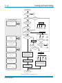
Corrected altitude = Altitude measurement - Altitude correction value
reference level
inst
STATIC
AIR DATA
COMPUTER
altitude
correction
value
2
PITOT
reference level
Zone 2 defined hazardous area
FIGURE 2-3 ADTS 405F ALTITUDE REFERENCE
K114 Issue No. 9
Druck ADTS 405 User Manual
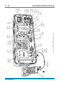
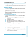
FIGURE 2-4 ADTS 405 GENERAL VIEW
2 - 10
K114 Issue No. 9
2 - 11
FIGURE 2-5 ADTS 405 REAR PANEL VIEW
Installation
K114 Issue No. 9
2
K114 Issue No. 9
Hand
terminal
Connector cable
(2m or 18m)
NNECT WHEN
DO NOT DISCO
DOUS AREA
IN THE HAZAR
ENERGIZED
DRUCK ADTS 405 HAND TERMINAL
ATEX COMPLIANT
Cover plate
for option
connectors
Static
output
connector
Solenoid
valve status
indicator
Pitot
output
connector
Pump
switch
Fan
outlet
cover
Calibration
enable
switch
Elapsed
time
indicator
Power
supply
switch
Altitude
reference
System
status
indicator
FIGURE 2-6 ADTS 405F GENERAL VIEW
ARINC 429/
Altimeter
encoder
connector
(optional)
Key-pad
and
display
Vacuum
input
connector
Auxiliary
Vacuum
input
connector
Pressure
input
connector
AC power
supply
connector
DC power
supply
connector
(optional)
DC and
AC power
supply
fuses
2 - 12
Druck ADTS 405 User Manual
Druck ADTS 405 User Manual
3
OPERATION
3.1
Preparation
3-1
WARNING:
OBSERVE SAFETY PRECAUTIONS STATED IN LOCAL ORDERS AND THE
AIRCRAFT OR EQUIPMENT SERVICING PROCEDURES.
Make sure the electrical and pneumatic connectors, electrical cables and pipes and
positioning of the ADTS 405 comply with the instructions and requirements in Section 2
Installation.
Carry out the following before use:
If necessary, carry out the maintenance task detailed in Section 4.
Make sure the air data test system power supply switch on the front panel is set
to OFF. Connect the air data test system to the electrical supply, make sure the
supply includes a connection to a protective earth.
Inspect the pneumatic hoses for damage, ingress of dirt and moisture. Make
sure the aircraft adaptors are serviceable.
Connect, to the air data test system, the hoses necessary for the test procedures to be
carried out: red hose to the STATIC output (Ps), blue hose to the PITOT output (Pt).
Temporarily seal the free ends of the hoses.
Note: When connected, take care not to kink or stand on the hoses.
Connect the hand terminal to the air data test system through the HAND TERMINAL
connector on the front panel. If necessary, connect the hand terminal through the
extension cable.
Before use, the ADTS 405 should be tested, for first time users see section 3.4, for users
requiring more operating detail see section 3.5.
This section contains a quick reference chart showing all the functions of the key-pad.
Further quick reference charts show the set-up and configuration settings for each
key-pad function.
Review and become familiar with the whole procedure before starting the test process
on an aircraft or component.
K114 Issue No. 9
3
3-2
3.2
Operation
Display Functions and Units of Measure
When operating in either pressure measuring or pressure controlling modes, the ADTS
405 can display the following information:
Aeronautical Functions
Display Abbreviation
Displayed Units
(if applicable)
Altitude
Calibrated and True Airspeed
Mach
Rate of Climb
Rate of Airspeed
Rate of Mach
Pressure Functions
ALT
CAS, TAS
MACH
ROC
Rt CAS,
RtMCH
Display Abbreviation
ft, m
kts, km/h, mph
ft/m, m/m, m/s, hm/m
kts/m, km/h/m, mph/m
Mach/m
Displayed Units
(if applicable)
Static (Absolute)
Ps
[P]
Pitot (Absolute)
Pt
[P]
Dynamic or Impact (Differential)
Qc
[P]
Engine Pressure Ratio
EPR
Rate of Ps
Rt Ps
[P] /m
Rate of Pt
Rt Pt
[P] /m
Rate of Qc
Rt Qc
[P] /m
Rate of EPR
Rt EPR
EPR/m
Where [P] is the currently selected pressure units from the following list:
mbar, inHg, mmHg, inH2O (4°C), inH2O (20°C), psi, hPa, kPa, inH2O (60°F), kg/cm2, %FS
FIGURE 3-1 FRONT PANEL
K114 Issue No. 9
Druck ADTS 405 User Manual
3.3
3-3
Quick Reference
The quick reference chart shows normal operation key functions. In the key/selection column the following applies:
ALT
[NEXT]
(SINGLE DOUBLE)
(craft1 craft2...)
data entry
-
Key.
Item in menu (soft key).
Sequence of parameters selected by NEXT key.
Sequence of names selected by NEXT key.
Enter number from key-pad.
KEY-PAD FUNCTION
the display shows the main pressure display (Leak Measure or Control mode).
Key/selection
Function and comments
F1-F4
Function keys for menus
ALT Ps
SPEED Qc
MACH Pt
EPR
ROC Ps RATE
RATE TIMER
F1
F2
F3
HOLD
RATE
LEAK MEASURE/CONTROL
Altitude (Aeronautical units) or Ps (Pressure units)
Airspeed (Aeronautical units) or Qc (Pressure units)
Mach (Aeronautical units) or Pt (Pressure units)
Engine Pressure Ratio (pressure units only)
Rate of Climb (Aeronautical units) or Rate of Ps (Pressure units)
Start timing rate of change
Wait and time choice 1
Wait and time choice 2
Wait and time choice 3
Hold pressure at present value - Press again to release
Rate of change of Pitot parameter - Press Pitot parameter then RATE
Switches between measure mode (for leak testing) and control mode
GROUND
[GO TO GROUND]
[DISPLAY QFE]
[DISPLAY QNH]
Controls Ps to atmospheric pressure and Qc to zero at current rates of
change
Display local atmospheric (ground) pressure
Display sea level equivalent of local atmospheric pressure
PORT
REMOTE
PRINT
See Line Switching Unit User Manual
Switches (toggles) between remote and local operation
Prints current parameter values
Inserts alphabet character in user text
Deletes last character of user text
Numeric entry for user text
[ALPHA]
[BACK]
data entry
3
EXECUTE TEST PROGRAM
[NEXT]
[PREV]
[RUN]
F1
F2
HELP
SETUP
See QUICK REFERENCE SETUP or MINIMUM SETUP
SETUP + F1
See QUICK REFERENCE - CONFIG
Execute down-loaded Test Programs
Select next listed test program
Select previous listed test program
Execute selected test program
Execute all tests in the test program
Selects and executes a specific test program
Press HELP then other key for further information
Temporary set-up - lost at power down
(nudge up)
(nudge down)
0-9
-000
CLEAR/QUIT
ENTER
CLEAR/QUIT + ENTER
Increases aim value
Decreases aim value
Number entry
Minus sign for first number entry 000 (thousand) if not first number of entry
Clear number entry - quit from menu or clear warning message
Complete number entry
ABORT - restart with power-up
Configuration - changes power-up defaults
Hold F1 while pressing SETUP - then enter PIN
K114 Issue No. 9
3-4
Operation
3.4
First Time Operators
The following sequences of operation should be used by first time operators and by
operators that use the equipment occasionally. For regular users, familiar with the
equipment, go to section 3.5. Set the power supply switch to OPERATE and the powerup routine starts.
(1)
The display, on the front panel or hand-terminal, shows:
DK126
Iss 1.xx
Display Power Up
Please Wait
(2)
After a short time the display shows:
DRUCK
ADTS 405
DK263
VER 6.xx
Note:
Where x is the current issue number of the software.
(3)
Last Calibration
dd/mm/yy (dmy)
RPT Transducer
PLEASE WAIT
Note:
Date format can be changed in configuration.
For units fitted with the Solartron transducer, the display shows Solartron Transducer in
place of RPT Transducer.
(4)
Self Test
PLEASE WAIT
K114 Issue No. 9
Druck ADTS 405 User Manual
(5)
3-5
The system opens the zero valves and after approximately 7 seconds the valves close
and the routine continues with the display shows:
Measuring Ground
Pressures
PLEASE WAIT
(6)
The system opens the output valves and controls pressures at the original measured
values.
Equalising System
Pressures
(Valves May Pulse)
PLEASE WAIT
(7)
At switch on, check the hand-held terminal display.
Note:
The ADTS 405 is a continuous, self-monitoring system. If the system detects an error, the
display shows an error message. Lists of errors are detailed in Section 5, Fault Finding
and Testing.
ALT
0
Leak Measure
3
ft
WARMUP
Note:
Wait 15 minutes, before continuing, to allow the system to get to thermal stability. The
wait time can be reduced to 5 minutes if the system has been re-powered after a short
time.
Operating modes
The air data test system can now be set for a variety of functions and modes. In the
following, examples of measure mode, control mode, leak measure mode and go-toground show the key presses and selections required for each mode.
K114 Issue No. 9
3-6
Operation
Measure Mode
To select the measured parameter press:
STATIC
PITOT
SPEED
ALT
Ps
or
Measured value
Measured
parameter
"leak-measure" when
measure mode selected
Qc
Pt
or
Units of
measurement
10000
Alt
Leak Measure
ft
CAS
350
Leak Measure
kts
Change display
single, dual or triple
press:
SETUP
Change units from aeronautical
to pressure:
SETUP
[MORE]
[CONTROL]
[Ps Pt DUAL]
[DISPLAYS/OPTIONS]
[DISPLAY TYPE]
[OPTIONS]
K114 Issue No. 9
MACH
[UNITS]
[NEXT]
[PREV]
[SAVE]
Druck ADTS 405 User Manual
3-7
Control Mode
3
K114 Issue No. 9
3-8
Operation
Leak Measure Mode
Note:
Compressing a gas generates heat. Gas heated or cooled in an enclosed volume
causes a pressure change. It is important, especially for leak testing, to allow enough
time for the heated gas to cool and the pressure to stabilize. When setting the rate
timer consider three factors:
1
2
3
K114 Issue No. 9
The volume of the system to be tested (large volumes take longer to stabilize).
The pressure change (the higher the change the greater heat generated).
The ambient air temperature.
Druck ADTS 405 User Manual
3-9
Go to Ground
3
K114 Issue No. 9
3 - 10
Operation
3.5 Operation and Example Procedures
3.5.1 Checks Before Use
Inspection and Cleaning
Inspect the external of the ADTS 405, and its associated equipment, for damage, dirt,
and the ingress of moisture. If necessary, use foam cleaner and a lint-free cloth to
clean the external surfaces.
Inspect the pressure outlet ports for ingress of dirt and moisture, clean if necessary
with a lint-free cloth.
3.5.2 Operating Procedures
The procedures show the steps required to make sure the ADTS 405 is serviceable and
the settings required to test an aircraft system or component. For further information
refer to the quick reference charts, at the end of this section, and Section 6 - Reference
and Specification.
In the following:
All key presses are highlighted in bold and shown as identified on the key-pad.
Key presses inside brackets e.g., [MORE], are soft key presses (i.e., function key
selections {F1 to F4} indicated on the display screen).
Help System
The help information includes further details of the function and details associated
functions, also see the Reference Section 6.
3.6
Power-up
Check the power indicator is illuminated and set the front panel power switch to
OPERATE.
The display shows the following sequence:
a. Display power-up screen.
b. ADTS 405 power-up screen.
c. Date of the last calibration and type of main transducer fitted.
d. Self-test message.
e. Measuring ground pressure message.
f. Equalising system pressures message.
g. Display shows Leak Measure mode and the number of parameters last selected in
configuration.
The ADTS 405 always powers-up in Leak Measure mode with the pressure controllers
off. When changing to Control Mode the pump unit must be switched on and
producing the correct pressure and vacuum.
Note: The display at power-up can be changed, see CONFIGuration.
K114 Issue No. 9
Druck ADTS 405 User Manual
3 - 11
The ADTS 405 system may now be used but for full specification accuracy and
stability, wait the "WARMUP" period of 15 minutes. The display shows “WARMUP” in the
lower right hand corner, this message clears automatically after the time period.
3.7
Control or Measure Parameter
To change the displayed parameter:
Value parameters Press the parameter key
e.g., press SPEED/Qc to display airspeed.
Rate parameter
Press the associated parameter key followed by the rate
key for that channel. e.g., display airspeed rate, press
SPEED/Qc then RATE. ROC/Ps Rate may be directly
pressed without first pressing ALT/Ps.
Note: The displayed parameters depend on the last keys pressed.
-
To display two parameters:
Press each value parameter in turn.
e.g., display altitude and airspeed together, press ALT/Ps then SPEED/Qc.
In control mode, an arrow, at the right-hand end of the aim value, indicates
the last parameter selected. This can be changed by entering a new value.
To display a value parameter together with its rate:
Press the parameter key followed by the associated rate key.
e.g., display airspeed and rate of speed together, press SPEED/Qc then RATE.
See Rate set-up for display details.
Note: If ROC/Ps Rate is pressed, the display automatically shows ALT and ROC.
3
Aim
A new aim can be entered using the numeric keys. Each digit is displayed as it is
pressed. The existing aim is replaced when the first digit of the new aim is pressed. If
an error is made during the entry of data, press CLEAR/QUIT to restore the original
aim.
Press ENTER to action the new aim.
Note 1:
The 000 key can be used as a quick way of entering thousands.
Note 2:
The ADTS 405 must be in control mode to enter a new aim (current aim
displayed). If the aim field shows "Leak Measure" press LEAK MEASURE/
CONTROL to enter control mode.
K114 Issue No. 9
3 - 12
Operation
3.8
Leak Testing the ADTS 405
It is important to check that the ADTS 405 and the connecting equipment does not
leak. Before use a leak check should be carried out as follows:
Connect the pitot and static hoses (to front panel of ADTS 405F). Temporarily seal the
free ends of the hoses.
Set the display to dual display, see 3.9.
Set the units to feet and knots, see 3.13.
Using the SETUP menu, choose the limits set for the aircraft or UUT, see 3.14.
Press SETUP, [LIMITS], and [NEXT] repeatedly to select the limit set from those
available.
Press [SEL] to save and then press CLEAR/QUIT repeatedly until the main
pressure screen shown below is displayed.
Note:
The numeric value of the parameters displayed change with each power-up
sequence. The amount of change depends on local atmospheric pressure
conditions at the time of power-up.
FIGURE 3-2 MAIN PRESSURE DISPLAY (LEAK MEASURE MODE)
Press the LEAK MEASURE/CONTROL key to turn on the pressure controllers.
K114 Issue No. 9
Druck ADTS 405 User Manual
3 - 13
To apply an altitude of 5000 ft at a rate of climb of 6000 ft/min and an airspeed of 300
kts at a rate of 600 kts/min press the following keys:
SPEED/Qc then RATE to select rate of change of speed.
6, 0, 0, ENTER to set the rate.
SPEED/Qc to select airspeed.
3, 0, 0, ENTER to set an airspeed of 300 kts (airspeed [CAS] now starts increasing).
ROC/Ps Rate to select rate of climb.
6, 0, 0, 0, ENTER to set the rate of climb.
ALT/Ps to select the altitude.
5, 0, 0, 0, ENTER to set altitude (altitude [Alt] now starts increasing).
SPEED/Qc to view altitude and airspeed together.
Note:
When altitude and airspeed are changing at the same time, and automatic
airspeed rate is enabled, the system automatically adjusts the airspeed rate so
that the aim points are reached at the same time. The airspeed rate will not
exceed the entered aim value.
Wait for the aim values to be achieved.
Observe over a period of 1 minute that the value of Alt stays within ±10 ft and
the value of CAS with ±1 kt.
3
FIGURE 3-3 MAIN PRESSURE DISPLAY (CONTROL MODE)
K114 Issue No. 9
3 - 14
Operation
Leak Measure
Note: Compressing a gas generates heat. Gas heated or cooled in an enclosed volume causes
a pressure change. It is important, especially for leak testing, to allow enough time for
the heated gas to cool and the pressure to stabilize.
Press LEAK MEASURE/CONTROL to return to Leak Measure mode.
Press RATE TIMER, F3 - [Wait 05:00, Time 01:00].
Note: Different wait and time periods can be selected by pressing F1 or F2.
Wait until rate timer has completed and the results displayed.
Check rate of climb is less than ±100 ft/min and rate of airspeed (CAS) is less
than ±1 kt.
Press LEAK MEASURE/CONTROL to return to Control mode.
Press GROUND, F1, [Go to Ground].
Wait until for the display shows Safe At Ground.
After a successful leak test, the ADTS 405 is now ready to be connected to an aircraft
system or unit under test.
After an unsuccessful, first-time leak test, leave the system to achieve thermal stability
for a further five minutes, press CLEAR/QUIT and repeat the leak test. If the leak test is
now successful, the ADTS 405 is now ready to be connected to an aircraft system or
unit under test.
After another unsuccessful leak test, disconnect both hoses, check the condition of the
o-rings on the Ps and Pt connectors as detailed in the maintenance section and firmly
replace the blanking caps. Press CLEAR/QUIT and repeat the leak test procedure.
After a successful leak test without hoses connected, replace or repair the faulty
hose(s) and retest. If the ADTS 405 fails the leak test without hoses connected, switch
off and return the unit to the repair depot.
K114 Issue No. 9
Druck ADTS 405 User Manual
3 - 15
3.9
Displays (Fig 3.4, Fig 3.5 and Fig 3.6)
The display normally shows pressures and rates or aeronautical equivalents.
It can be set-up to show, at the same time, one parameter (single), two parameters
(dual) or three parameters (triple). The ADTS 405 automatically returns to the pressure
display if left inactive in any set-up or menu type display for a period of more than one
minute.
The triple display always shows altitude and airspeed; with pressure units selected, the
display always shows Ps and either Qc, Pt or EPR. When ALT or CAS are selected the
display shows the aim and measured values of ALT and CAS as a dual display. With
any other selected parameter the display shows the measured values of altitude and
airspeed and, the aim and measured value of the other selected parameter.
Additional display modes are available for options.
3
FIGURE 3-4 SINGLE DISPLAY
K114 Issue No. 9
3 - 16
Operation
FIGURE 3-5 DUAL DISPLAY
FIGURE 3-6 TRIPLE DISPLAY
K114 Issue No. 9
Druck ADTS 405 User Manual
3 - 17
3.10 Rate Timer Displays (Fig 3.7 and Fig 3.8)
When in Leak Measure mode and, after completing a rate timing, the system generates
the rate timer displays. These displays do not depend on the display mode (single,
dual, triple or option). Pressing a parameter key (ALT, ROC, etc.,) or CLEAR/QUIT exits
the rate timer displays.
FIGURE 3-7 RATE TIMER DISPLAY AERONAUTICAL UNITS
3
FIGURE 3-8 RATE TIMER DISPLAY PRESSURE UNITS
Note:
There is no pointer for the primary parameter, values cannot be entered in
the rate timer displays.
K114 Issue No. 9
3 - 18
Operation
3.11 Pt Only Display (Fig 3.8)
The Pt only display overrides the other display modes (single, dual and triple). The
measured altitude and the CAS are produced from Ps in measure mode.
FIGURE 3-9 PT ONLY DISPLAY
3.12 Changing the Display
The display can show either one, two or three parameters as follows:
Note: Display cannot be changed with SETUP switched off or in minimum mode.
To change the display:
Press SETUP.
Select [MORE].
Select [DISPLAYS/OPTIONS].
Select [DISPLAY TYPE].
Using [NEXT] or [PREV].
Select either SINGLE, DUAL or TRIPLE, ARINC, ENCODER
(more display types with options fitted).
Press [SAVE] to accept.
Press CLEAR/QUIT repeatedly to return to user display.
To change the display for Pt Only:
Press SETUP.
Select [MORE].
Select [Control], [Ps Pt Dual].
Select [Pt Only Mode].
Press CLEAR/QUIT repeatedly to return to user display.
K114 Issue No. 9
Druck ADTS 405 User Manual
3 - 19
3.13 Changing the Units
The units can be changed to units of pressure measurement or aeronautical units.
In Full Set-up Mode any set of aeronautical or pressure units can be selected.
To change the units:
Press the SETUP key.
Select [UNITS].
Use [NEXT] and [PREV] keys to select the required units.
Select [SAVE] to accept.
Press CLEAR/QUIT repeatedly to return to the main pressure display.
In Minimum Setup Mode only the default aeronautical and pressure units can be
selected.
To change the unit type:
Press the SETUP key.
Select [UNITS TYPE].
Select either [AERO] or [PRESS] to select the unit type.
Select [SAVE] to accept.
Press CLEAR/QUIT repeatedly to return to the main pressure display.
Note: The default pressure and aeronautical units are defined in the CONFIGuration
mode.
If Set-up Mode is switched off, units cannot be changed.
3
3.14 Limit Checking
The system checks all data entered against minimum and maximum limits set for the
particular limit set in use. If these limits are exceeded, the data entry is ignored and a
warning message displayed showing the minimum and maximum values that can be
entered. The system also checks all limits of associated parameters. If these limits are
exceeded when a new value is entered, the display shows the name of the associated
parameter.
e.g., If a Mach limit is exceeded when entering an airspeed value the display shows
"Mach" and the equivalent maximum and minimum limits as airspeed values. Similarly,
if an ARINC 565 limit is exceeded when entering a value and, ARINC limits are enabled,
the display shows `ARINC'.
K114 Issue No. 9
3 - 20
Note:
Operation
Using the SETUP function, previously stored sets of limits can be recalled for use. Each
set of limits is stored under an aircraft name. Three pre-defined sets of limits
“Standard“, “Civil“ and “Max“ limits are supplied with the ADTS 405.
The ADTS 405, when delivered, contains "Standard" and "Civil" limits; to set and store
"Max" limits, for the first time, enter configuration. The "Max" limits depend on the
range of the pitot channel either 850 or 1000 knots, see section 1.3, operating limits.
To select the limits in use:
Press SETUP.
Select [LIMITS].
Use [NEXT] or [PREV] to select the limits required. Each set of limits
is identified by its name, including the pre-defined sets of limits (“Standard“, “Civil“
and "Max" see section 1.3, operating limits).
Select [SEL] to select the limits.
Press QUIT/CLEAR to return to the pressure display.
Using the CONFIGuration function, new sets of limits can be created and existing sets of
limits can be edited. In addition, the set of limits in use at power-up can be selected. If
required, this selection can be locked to prevent unauthorised changing of the limits.
Auto recovery facilities
The pressure controllers in the ADTS 405 can "feed" a leak in an aircraft system. When
first testing an aircraft system, a leak test must be carried out at low altitude and
airspeed.
If, during a leak test, a leak in the system produces a rate of climb greater than the rate
set in limits or a rate of change of airspeed greater than the rate set in limits, then the
pressure controllers automatically regain control to minimise damage to the aircraft
system. This AUTO LEAK RECOVERY facility can be disabled.
If a leak causes the system pressures to exceed any limit during a leak test, the
pressure controllers automatically regain control. This AUTO LIMIT RECOVERY system
can be disabled.
If negative airspeed (or Qc) occurs in measure mode, the zero value is automatically
opened for one second to balance the airspeed. This only applies when the minimum
CAS (or Qc) limit is zero.
Limits cannot be changed with SETUP switched off or Limit Lock enabled.
K114 Issue No. 9
Druck ADTS 405 User Manual
3 - 21
Aircraft System Protection
The ADTS 405 protects the aircraft system against user error and leaks in the aircraft
system.
Note: The pumps must be switched on.
The system protection operates:
Limit checking of user entered set-points.
Automatic regain of control if leak rate is over limit during leak testing.
Automatic regain of control if a leak takes the system pressures outside of
limits.
Mach Test and Constant Mach
To go to 0.8 Mach, enter Control Mode and proceed as follows:
Press SPEED then RATE to select rate of change of airspeed.
Enter required rate, e.g. 300 kts/min.
Press MACH.
Enter 0.8.
Wait for the Mach to be achieved.
Note:
If the altitude changes the system automatically adjusts the airspeed to
keep the Mach value constant.
True Airspeed
The normal airspeed parameter is Calibrated Airspeed (CAS) (equivalent to IAS for
testing purposes).
The airspeed parameter may be changed to True Airspeed (TAS) as follows:
Press SETUP then SPEED.
Select [CAS/TAS].
Select [TAS].
Press QUIT/CLEAR repeatedly to exit set-up.
Press SPEED.
The display now shows the airspeed parameter as TAS.
Note:
Airspeed parameter type can only be changed in Full Set-up mode. Rate of
change of airspeed will still be shown as Rate CAS.
Pitot temperature (Tt) is used in the calculation of TAS. To enter Tt:
Press SETUP.
Press SPEED.
Select [Pt TEMPERATURE].
Enter the temperature measured by the aircraft's Pitot temperature sensor.
Press QUIT/CLEAR three times to return to user display.
Note: Pitot temperature can only be changed in Full Set-up mode.
K114 Issue No. 9
3
3 - 22
Operation
Airspeed Switch test
The following example shows how an airspeed switch an be functionally checked.
Note: For low airspeed switches (i.e. 130 knots) the Pt Only facility could be used.
Press LEAK MEASURE/CONTROL to enter control mode. Press SPEED/Qc.
If necessary, press RATE and enter a change of airspeed low enough to observe switch
operation.
Enter an Aim value below the operating limits of the switch (i.e., airspeed switch
operating at 130 knots ±2 knots set 127 knots).
Press ENTER and observe the airspeed changing.
Using the nudge facility, set to an appropriate step value, increase the Aim value.
Increase the Aim until the switch operates (contacts close) and record the value.
Change the Aim to above the airspeed operating range (i.e. 133 knots). Repeat the
steps, decreasing the Aim value until the airspeed switch operates (contacts open) and
record value.
This procedure can be repeated. If many operations of a switch are required use the
oscillating facility detailed in Full Set-up. The above method can be used for the other
parameters:
Examples:
Altitude switch
Mach switch
K114 Issue No. 9
-
low altitude warning
landing gear configuration warning
height lock
Speed brake scheduling
Mach cruise lock
Druck ADTS 405 User Manual
3 - 23
Engine Pressure Ratio (EPR)
The ADTS 405 may be used to check EPR sensors and indicators. Use Ps for INLET
pressure and Pt for OUTLET pressure.
To carry out an EPR check, the display must be showing pressure units e.g., mbar or
inHg.
To change units in FULL SETUP Mode:
PressSETUP.
Select [UNITS].
Select required pressure units for display using [NEXT], [PREV] and [SAVE].
Use CLEAR/QUIT to return to pressure display.
To change units in MINIMUM SETUP Mode:
Press SETUP.
Select [UNITS TYPE].
Select [PRESS].
Use CLEAR/QUIT to return to the main pressure display. Pressure units cannot
be selected when set-up mode is switched off.
To enter an EPR of 1.8 with inlet pressure of 500 mbar (15 inHg), proceed as follows:
If the display shows “Leak Measure”, press LEAK MEASURE/CONTROL to regain
control.
Note: The pressure/vacuum pumps must be switched on.
Press ROC/Ps RATE to select rate of change of static.
Enter required rate of change e.g., 1000 mbar/min, (30 inHg/min).
Press EPR then RATE to select EPR rate.
Enter required value e.g., 5 EPR/min and press ENTER.
Press ALT/Ps.
Enter 500 mbar (15 inHg) and press ENTER.
Press EPR.
Enter 1.8 and press ENTER.
An EPR of 1.8 will quickly be achieved.
Note: EPR testing can also be performed by specifying the actual INLET and OUTLET
values.
K114 Issue No. 9
3
3 - 24
Operation
3.15 Testing Aircraft Systems or UUT
WARNING:
OBSERVE THE APPROPRIATE SAFETY INSTRUCTIONS AND PROCEDURES
DETAILED IN THE AIRCRAFT MAINTENANCE MANUALS OR COMPONENT
MAINTENANCE MANUALS.
Connect the hoses and appropriate adaptors to the aircraft system or UUT.
To make sure that the connections to the aircraft system or UUT are not leaking carry
out a leak test detailed in the appropriate aircraft or component manual.
3.15.1
Go To Ground and Shut-down
On completion of testing and, before disconnecting from the aircraft system or UUT,
the pressures in the system must be taken to the local atmospheric pressure (ground)
with zero airspeed.
If the display shows "Leak Measure", press LEAK MEASURE/CONTROL.
Press GROUND, F1, [Go To Ground].
Wait for the display to show "Safe At Ground". It is now safe to
disconnect the aircraft system or UUT.
The pressure in the system changes towards ground. The ground pressure or "Ground"
replaces the static or altitude aim value.
If required, new rates of change can be entered while going to ground.
To change the ROC or static rate, press ROC/Ps Rate and enter the new value.
To change the airspeed or Qc rate, press SPEED/Qc then RATE and enter the new
value.
To change from going to ground, enter a new altitude (static) or airspeed (Qc) set-point.
When the airspeed reaches zero and the Ps channel pressure nears ground, the
system re-measures atmospheric pressure to update the recorded ground pressure
(QFE). During this period, the display shows the message "Checking Ground". The
ADTS 405 then reconnects to the aircraft system and equalises the system pressures.
Commands cannot be entered when these two messages are displayed.
The Ps channel pressure is then taken to the new recorded atmospheric pressure and,
at this new pressure, the display shows the message “Safe At Ground”. The ground
vent and zero valves remain open to keep the aircraft system vented to atmosphere.
Press CLEAR/QUIT to continue with normal operation. The ground vent and zero
valves automatically close.
K114 Issue No. 9
Druck ADTS 405 User Manual
3 - 25
3.16 Options
WARNINGS:
1.
COMPLY WITH ALL LOCAL SAFETY ORDERS.
2.
OBSERVE ALL SAFETY PROCEDURES IN THE AIRCRAFT MAINTENANCE
MANUALS.
SCPI IEEE 488 Option
The SCPI IEEE 488 interface provides remote control of the ADTS 405 from a suitable
PC, using standardised commands.
The ADTS 405 implements the full SCPI command set with the exception of expressions
and units suffixes. Although all the ADTS 405 commands at the first, or root, level are
fully defined in the SCPI standard, many of the functions required have not been
allowed for in the standard. The lower levels of commands have been created using
the appropriate rules contained within the standard.
Druck publication K157 SCPI User Manual provides details of command codes,
command syntax and examples of programming. Section 5 of this manual details a
test procedure for the option.
Altimeter Encoder Option
The Altimeter Encoder Option allows the output from encoder altimeters to be
displayed on either the hand terminal or display and key-pad of the unit. The
displayed data includes the bit pattern and the equivalent altitude decoded from the
bit pattern. The unit supplies 24 VDC to power the altimeter encoder electronics circuit
and the altimeter vibrator circuit.
Druck publication K170 Altimeter Encoder Option User Manual provides details of
displayed and encoded data. Section 5 of this manual details a test procedure for the
option.
ARINC 429 Option
The ARINC 429 Interface provides the ADTS 405 with the ability to continuously
transmit all internal aeronautical and pressure measurement parameters. Through an
appropriate connector, the ADTS 405 can transmit the measurement parameters to
the aircraft systems. The ADTS 405 can also monitor the aircraft ARINC 429 bus and
display the measurement data on the hand terminal or the front panel display. The
labels used for transmitting and receiving each parameter conform to the standard
429 specification.
Druck publication K185 ARINC 429 Option User Manual provides details of parameters
and data output. Section 5 of this manual details a test procedure for the option.
K114 Issue No. 9
3
3 - 26
Operation
3.17 SETUP and CONFIGuration
The SETUP key provides access to secondary functions using a menu system, extends
the keyboard and allows many of the ADTS 405 functions to be customised. All
changes made under SETUP are temporary and will be lost when the system is
switched off. The range of options allowed in set-up is determined by the set-up mode.
Holding down the F1 key while pressing SETUP provides access to the CONFIGuration
mode. CONFIGuration is similar to SETUP with many identical functions. The changes
made under CONFIGuration are permanent and remain set after the system is
switched off. CONFIGuration can be used to change the power-up default settings of
the ADTS 405 functions.
Note: Access to the CONFIGuration mode may be protected by a PIN.
3.18 Quick Reference
The quick reference charts show full set-up, minimum set-up and configuration
functions. In the key/selection column the following applies:
ALT
[NEXT]
(SINGLE DOUBLE)
(craft1 craft2...)
data entry
-
Key.
Item in menu (soft key).
Sequence of parameters selected by NEXT key.
Sequence of names selected by NEXT key.
Enter number from key-pad.
The display shows the main pressure display (Leak Measure or Control mode).
Set-up example
Press SETUP and the display shows:
Pressing a function key (F1 to F4) enters the set-up menu.
When in set-up, pressing a key
(ALT Ps in this example) enters
a menu or setting that applies
to the parameter.
K114 Issue No. 9
Druck ADTS 405 User Manual
3 - 27
FULL SET-UP
Key/selection
Function and comments
SETUP
[UNITS]
[NEXT]
[PREV]
[SAVE]
[LIMITS]
[NEXT]
[PREV]
[SEL]
[OSC]
[Ps]
[START]
[STOP]
[FREEZE]
[AMPL/FREQ]
[AMPL]
Data Entry
[FREQ]
Data Entry
[Pt]
[MORE]
[CONTROL]
[Ps Pt DUAL]
Full or minimum set-up selected in configuration.
Select units
Step through available units
Step back through available units
Select displayed units
Select set of limits
(aircraft 1\aircraft 2 ...)
As NEXT, in reverse order
Select displayed limit set
Oscillate about aim
For Ps channel
[DISPLAYS/OPTIONS]
[DISPLAY TYPE]
[NEXT]
[PREV]
[SAVE]
[OPTIONS]
[CLOSE O/P VALVES]
[OPEN O/P VALVES]
[SYSTEM SELF TEST]
As for Ps channel
Selects Ps only, Pt only or Dual channel control
Select single, dual or triple display
(SINGLE\DUAL\TRIPLE\ENCODER\ARINC429)
As NEXT, reverse order
Save displayed Display Type
See option manual
Close output valves
Open output valves
Start self test
3
SETUP + KEY PRESS
R
e
f
e
r
e
n
c
e
ALT
data entry
SPEED
[AUTO ZERO]
[ON]
[OFF]
[CAS/TAS]
[CAS]
[TAS]
[Pt TEMPERATURE]
data entry
MACH
[DEFAULT]
[OFF]
[ON]
data entry
Altitude correction value
Auto zero function
Calibrated or true airspeed
Temperature for true airspeed
Enter Pitot temperature
Mach limit
Defined by current limits
Removes Mach limit
Enables Mach limit
Enter new Mach limit
¾ SETUP contd...
K114 Issue No. 9
3 - 28
Operation
FULL SET-UP (contd.)
Key/selection
SETUP contd...
RATE TIME
[WAIT/TIME ON F1]
[TIME]
[WAIT]
data entry
data entry
[WAIT TIME F2]
[WAIT TIME F3]
Function and comments
Set-up WAIT and TIME time periods
For F1
Change to TIME
Change to WAIT
of TIME time
of WAIT time
See [Wait/Time on F1]
See [Wait/Time on F1]
Automatic airspeed rate
RATE
[ON]
Automatic
[OFF]
Manual
LEAK MEASURE
[AUTO LEAK]
[ON]
[OFF]
[AUTO LIMIT]
[ON]
[OFF]
GROUND
data entry
Auto limit recovery on or off
PORT
See Line Switching Unit User Manual
Auto leak recovery on or off
Airfield altitude for QNH display
Remote mode lock, see configuration
REMOTE
PRINT
[DATE/TIME]
[DATE]
data entry
[TIME]
data entry
HELP
(Nudge UP)
[NEXT]
data entry
[PREV]
data entry
(Nudge DOWN )
K114 Issue No. 9
Adjust date and time
Enter Date
Enter Time
Help on SETUP
Enter nudge values
(ALT \ CAS / TAS \ MACH \ ROC \ RATE \ RATE CAS) Aeronautical units or
(Ps \ Pt \ Qc \ EPR \ RATE Ps \ RATE Qc \ RATE EPR) Pressure units
As NEXT, in reverse order
Required nudge increment
As Nudge UP
Druck ADTS 405 User Manual
3 - 29
MINIMUM SET-UP
Key/selection
SETUP
[UNITS TYPE]
[AERO]
[PRESS]
Function and comments
Full or minimum set-up selected in configuration.
Set units type
Set units to default aeronautical units
Set units to default pressure units
[LIMITS]
[NEXT]
[PREV]
[SEL]
Select set of limits
(aircraft 1\aircraft 2 ...)
As NEXT, in reverse order
Select displayed limit set
ALT
Altitude correction value
data entry
PORT
See option user manual
HELP
Help on set-up
EXECUTE TEST PROGRAM
[PRINT/SAVE]
[PRINT]
[SAVE]
[PRINT FILE]
[NEXT]
[PREV]
[PRN]
Result file related print option
Print/save mode selection
Print generated result data
Save generated result data to file
Print result file option
Select next result file
Select previous result file
Print selected result file
3
R
e
f
e
r
e
n
c
e
K114 Issue No. 9
3 - 30
Operation
CONFIGURATION
Key/selection
SETUP + F1
[UNITS]
[AERONAUTICAL]
[NEXT]
[PREV]
[SAVE]
[PRESSURE]
[NEXT]
[PREV]
[SAVE]
[TEMPERATURE]
[C]
[F]
[LIMITS]
[EDIT LIMITS]
[EDIT EXISTING]
[NEXT]
[PREV]
[SEL]
[NEXT]
[PREV]
[ON/OFF]
data entry
[ALPHA]
[BACK]
[MAX LIMITS]
[EDIT NEW]
[CLEAR LIMITS]
[NEXT]
[PREV]
[SEL]
[YES]
[NO]
[LOCK AIRCRAFT]
[ON]
[OFF]
[DEFAULT AIRCRAFT]
[NEXT]
[PREV]
[SEL]
¾ SETUP + F1 contd...
K114 Issue No. 9
Function and comments
Hold F1 and press SETUP to enter CONFIG
Default units
Select default aeronautical units
Step through available units
Step back through available units
Save selected units
Select default pressure units
Step through available units
Step back through available units
Save selected units
Select default temperature units
C
F
Configure sets of limits
Change limit values
Change existing values
(aircraft 1 \ aircraft 2 ..._
As NEXT, in reverse order
Select aircraft to EDIT limits
NAME \ MAX ALT \ MIN ALT \ MAX CAS \ MIN CAS \ MAX MACH \ MAX ROC \ MAX
RATE CAS \ MIN Ps \ MAX Ps \ MIN Qc \ MAX Qc \ MAX RATE Ps \MAX RATE Qc \
ARINC LIMITS \ ALTITUDE CORRECTION
As NEXT in reverse order
Switch (toggle) to ARINC 565 limits
Limit value
Insert alphabet character in name
Nudge up select next letter in alphabet
Nudge down select previous letter in alphabet
Delete last character in name
Create maximum limits called "MAX"
Create new limits
As for [EDIT EXISTING][SEL] above
Clear an existing set of limits
(aircraft 1 \ aircraft 2 ...)
As NEXT, in reverse order
Clear selected limits
Confirm delete
Only DEFAULT limits available in USER mode
SETUP can be used to select aircraft
(aircraft 1 \ aircraft 2 ...)
As NEXT, in reverse order
Select aircraft limits used at power-up. May be locked
Druck ADTS 405 User Manual
Key/selection
CONFIG (SETUP + F1) contd...
[MORE]
[CONTROL]
[Ps Pt DUAL]
[DISPLAY/OPTIONS]
[DISPLAY TYPE]
[NEXT]
[PREV]
[SAVE]
[OPTIONS]
[DATE FORMAT]
[DMY]
[MDY]
[SETUP MODE]
[OFF]
[MIN]
[FULL]
3 - 31
Function and comments
Ps Pt DUAL control
Ps single pipe testing of altimeters. Pt single pipe testing of airspeed and Mach
indicators. DUAL normal combined system testing.
Configure display type
(SINGLE\DUAL\TRIPLE\ENCODER\ARINC429)
As NEXT, in reverse order
Save selection
See option manual
Format of date text
UK format DD/MM/YY
US format MM/DD/YY
Limits access to set-up functions
CONFIG (SETUP + F1) + KEY PRESS
SPEED
[AUTO ZERO]
[ON]
[OFF]
[CAS/TAS]
[CAS]
[TAS]
[Pt TEMPERATURE]
data entry
¾
Auto zero function
Configure Calibrated or True airspeed
Configure Pt temperature
RATE TIME
[WAIT/TIME ON F1]
[TIME]
[WAIT]
data entry
data entry
[WAIT/TIME ON F2]
[WAIT/TIME ON F3]
Configure WAIT and TIME times
For F1
Change to TIME
Change to WAIT
TIME time period
WAIT time period
See [Wait/Time on F1]
See [Wait/Time on F1]
RATE
[ON]
[OFF]
Automatic airspeed rate
Automatic
Manual
LEAK MEASURE
[AUTO LEAK ON/OFF]
[ON]
[OFF]
[AUTO LEAK LOCK]
[ON]
[OFF]
[AUTO LIMIT ON/OFF]
[ON]
[OFF]
[AUTO LIMIT LOCK]
[ON]
[OFF]
3
R
e
f
e
r
e
n
c
e
Auto leak recovery Lock
Lock auto leak recovery Lock
Auto limit recovery state
Lock auto limit recovery state
CONFIG (SETUP + F1) + KEY PRESS contd...
K114 Issue No. 9
3 - 32
Operation
Key/selection
CONFIG (SETUP + F1) + KEY PRESS
Function and comments
contd...
GROUND
data entry
Airfield altitude for QNH display
PORT
Refer to option user manual
REMOTE
Remote mode lock
[ON]
[OFF]
ETP
AUTO RUN
[NEXT]
[PREV]
[NONE]
[SEL]
Run test program on power up
Refer to option user manual
ERASE PROGRAMS
[NEXT]
[PREV]
[DEL]
RESULTS
[PRINT/SAVE]
[PRINT]
[SAVE]
[ERASE FILE]
[NEXT]
[PREV]
[DEL]
Delete test program
Print/Save mode selection
Generated result data printed
Generated result data saved in a file
Result file delete option
Select next result file
Select previous result file
Delete selected result file
(nudge up)
[NEXT]
[PREV]
data entry
(ALT\CAS/TAS\MACH\ROC\RATE CAS\Ps\Pt\Qc\EPR\RATE Ps\RATE Qc\RATE EPR)
As NEXT, in reverse order
Required nudge increment
(nudge down)
As nudge up
[000]
data entry
K114 Issue No. 9
PIN protection
PIN (code number to enter CONFIG) set to 0000 for "no code required"
Druck ADTS 405 User Manual
4
Maintenance
4.1
Introduction
4-1
This section details the maintenance tasks to be carried out by the operator. The
maintenance chart shows the maintenance tasks, the periodicity of each task and a
code referenced to the task detailed in 4.3.
Task
Code
Period
Inspect
A
Daily, before use.
Inspect
B
Weekly
Test
C
Before use.
Test
D
Daily, before use.
Calibrate
E
Every 12 months *
Replace
F
As detailed in fault finding or when detailed after inspection.
Clean
G
Weekly *
Service
H
1,000 hours recorded by the pump unit elapsed time indicator
or the equipment running log.
Service
J
3,000 hours recorded by the pump unit elapsed time indicator
or the equipment running log.
* Periodicity may change depending on usage and environment, refer to the Engineering
Authority.
TABLE 4-1 MAINTENANCE CHART
4
K114 Issue No. 9
Maintenance
4-2
4.2
Materials
This lists materials required for the user to maintain the ADTS 405. The item number
and name in the table identifies the item in the maintenance tasks (for example, "Use a
soft bristle brush, item 4, Table 4-2").
The description provides further information required to identify the item.
Item
Nu mb er
Item Name, Descrip tio n
1
Cloth, Cotton, Lint-Free
2
Alcohol, Isopropyl (MIL-A-10428, Grade A)
3
Detergent, Mild, Liquid
4
Brush, Soft-bristle (MIL-B-43871)
Note:
Equivalent substitutes can be used.
TABLE 4-2 MATERIALS LIST
(1)
(2)
(3)
Ref Code
Nomenclature
Manufacturer’s
part number
1
Voltmeter, Digital
Fluke series II, Type 77 H7291
2
Insulation Tester, 250V
Robin
Note:
Equivalent substitutes can be used.
TABLE 4-3 TOOL AND TEST EQUIPMENT REQUIREMENTS
K114 Issue No. 9
Druck ADTS 405 User Manual
4-3
4.3
Maintenance Tasks
A
Visually inspect the unit for obvious signs of damage and check that all the equipment
is present; record any deficiencies.
B
Visually inspect the pneumatic output connectors for damage. Inspect the small o-ring
on each pneumatic output connector for cuts and any signs of wear; if necessary,
replace as detailed in 4.4. Visually inspect pneumatic hoses, electrical cables for cuts,
splits and damage; replace as necessary.
C
Before use, power-up the unit as detailed in Section 3. Check the date of the last
calibration and, if necessary, refer to task E. Record any error messages and refer to
Section 5.
D
Daily and before use, carry out the SST detailed in Section 5.
E
Normal calibration period 12 months. When calibration is due, the unit should be
withdrawn from service and returned to depot or calibration facility. The date of
calibration is stored in the unit and displayed in the power-up sequence and on a label
on the front panel. Do not use a unit with out-of-date calibration. Engineering
authority may change the periodicity of calibration depending on usage and the
operating environment.
F
As detailed in fault finding or when detailed after inspection replace the listed item in
table 2-1.
G
Clean the unit every week. Clean the front panel with a damp lint-free cloth (item 1,
Table 4-2) and mild liquid detergent (item 3, Table 4-2). Remove any stubborn dirt
using isopropyl alcohol (item 2, Table 4-2) and allow to dry. Clean all pneumatic
connectors with a soft brush (item 4, Table 4-2). Remove any stubborn dirt using
isopropyl alcohol (item 2, Table 4-2) and allow to dry.
H
Withdraw the unit from service and return to the repair depot. The intermediate
service manual contains the 1,000 hour servicing procedure.
J
Withdraw the unit from service and return to the repair depot. The intermediate
service manual contains the 3,000 hour servicing procedure.
4
K114 Issue No. 9
Maintenance
4-4
4.4
Routine Maintenance
WARNING:
SWITCH OFF AND DISCONNECT THE POWER SUPPLY BEFORE STARTING ANY MAINTENANCE TASK.
Carrying out the maintenance tasks detailed 4.3.
Servicing Procedures
The following procedures provide instructions to test and replace items for the operator.
Return the unit to the intermediate service depot for further testing and replacement of items.
Replacing the output connector o-ring
After inspection as detailed in maintenance task B, carry out the following if the o-ring is
worn or damaged:
Carefully remove the o-ring from the small groove
at the top of the connector.
Fit a new o-ring in the small groove at the top of
the connector.
Make sure the o-ring is tight in the groove and not
damaged after fitting.
Note: Damage to this o-ring causes leaks.
K114 Issue No. 9
Druck ADTS 405 User Manual
4-5
Cable tests
Carry out the following check when detailed in Testing and Fault Finding, Section 5.
Measure continuity using the DVM (item 1, Table 4-3) set to an appropriate range.
Measure the continuity between corresponding pins at each end of each cable
assembly. The measured resistance must not exceed 2.0 ohms.
Note: This resistance value is the expected maximum value for the 18 metre (60ft) cable.
The resistance value varies depending on the length of the cable.
Measure insulation using the Insulation tester (item 2, Table 4-3), set to an appropriate
range.
Measure the insulation resistance between the shell of the connector and all individual
pins in turn.
Measure the insulation resistance between the shell of the appropriate connectors and
all pins in turn.
Measure also the resistance between individual pairs of pins (i.e., 1-2, 1-3, 1-4, 1-5, 1-6,
2-3, 2-4, 2-5, 2-6, 3-4, 3-5, 3-6, 4-5, 4-6 and 5-6). In all cases the resistance must
exceed 10 Mohms.
4
K114 Issue No. 9
Maintenance
4-6
INTENTIONALLY LEFT BLANK
K114 Issue No. 9
Druck ADTS 405 User Manual
5-1
5
TESTING AND FAULT FINDING
5.1
Introduction
The ADTS 405 contains a built-in, self-test and diagnostic system. The system
continuously monitors the performance of the unit and at power-up carries out a selftest. Warning and error messages are displayed during normal operation if out of
range values are entered or if faults occur.
This section details the standard serviceability test and the possible error messages
and codes that can be displayed. A fault diagnosis flow chart and table provide the
probable cause and procedures to rectify specific symptoms.
Error messages
When the display shows a message indicating entry of incorrect data or values,
pressing QUIT clears the message and allows the correct entry to be made.
5
K114 Issue No. 9
Testing and Fault Finding
5-2
5.2
Standard Serviceability Test
The following procedure can be used to check the functions and facilities of the ADTS
405. For further information refer to Section 6 - Reference and Specification.
In the following:
All key presses are highlighted in bold and shown as identified on the key-pad.
Key presses inside brackets e.g., [MORE], are soft key presses (i.e., function key
selections {F1 to F4} indicated on the display screen).
Procedure
Connection and power-on checks
Connect power to the unit and, if necessary, connect the hand terminal.
Make sure that the blanking caps are fitted to the Ps and Pt front panel outputs.
Check power indicator is on.
Set the front panel switch to OPERATE. Set the front panel switch for the pump
unit to PUMP ON and check that the pump power indicator lights.
Check the display shows the first stage power-up message as below (where: x is
the version number of the installed display driver software):
DK 282 Version x.xx
Display Power up
Please Wait
Check the second stage power-up message displays as below (where: x is the
version number of the installed main operating software):
DRUCK
ADTS 405
DK 263
VER 6.xx
Note: "ADTS 405" may be replaced by an alternative identity string. The software version may
also be supplemented by extra alpha characters.
K114 Issue No. 9
Druck ADTS 405 User Manual
5-3
The ADTS 405 displays any detected errors. Check that the power-up sequence
continues through the following stages without error:
Calibration date.
Self-test.
Measuring ground pressures.
Equalizing system pressures.
Check that the display then changes to show measured altitude and airspeed (CAS or
TAS) values.
NOTES
1
The displayed values change as atmospheric pressure changes at power-up.
2
The display shows the “WARMUP” message in the lower right corner indicating
that full pressure accuracy and stability may not be achieved. The WARMUP
message clears after 15 minutes. This indication does not inhibit operation and
these tests may proceed without waiting for the message to clear.
3
An automatic zero (if enabled) takes place regularly. The display shows “ZERO”
and the state of the valves, on the mimic panel, change for approximately six
seconds. Commands may still be entered while auto-zero takes place.
Press the MACH key and check the display changes to show Altitude and Mach
measured values.
Pump unit
Set the front panel switch for the pump unit to PUMP ON and check that the pump
power indicator lights.
Press LEAK MEASURE/CONTROL to go to control mode. Enter an altitude aim of 5000
ft by pressing 5, 0, 0, 0, ENTER.
Enter rate or use default rates.
Enter an airspeed aim of 500 knots by pressing SPEED, 5, 0, 0, ENTER.
Check that these aim values are achieved.
5
Completion
On successful completion of this test procedure, select GROUND, [Go to Ground] wait
until the unit is at ground, switch off and disconnect the power supply.
K114 Issue No. 9
Testing and Fault Finding
5-4
5.3
Self-Test Errors
At power-up, the ADTS 405 indicates if there is a fault by displaying an error code for
example:
701:HHHH PS SELF-TEST ERROR
The HHHH is a hexadecimal code containing additional information record the whole
error code.
Paragraph 5.8 contains a table listing the error codes, check that the error code is
complete and listed in the table before returning the unit to the repair depot.
5.4
Venting after Overpressure
To calibrate or test the ADTS 405, an external pressure source is connected to the Ps
and/or Pt output connectors. If, during calibration or test procedures, an overpressure
occurs, the output valves close to protect the system. After the valves close pressure
may be trapped in the internal system; the display may show on the next power-up
error 701:0100 or 702:0100. The following procedure to vent this pressure enters the
maintenance mode. Review and become familiar with the whole procedure before
beginning the venting process:
1.
CAUTION:
2.
Remove the source of pressure and vent Ps and Pt to atmosphere (caps off).
ONLY SELECT ITEMS DETAILED IN THE FOLLOWING MENUS, INCORRECT SELECTIONS CAN CAUSE
CHANGES TO SAFETY LIMITS AND THE CALIBRATION DATA OF THE SYSTEM .
Re-power the ADTS 405. During the power-up screen:
DRUCK
ADTS 405
DK XXX
VER XXX
3.
Press F1 and F4 simultaneously. The ADTS 405 enters the maintenance mode
with the following screen displays.
Note: The system may prompt for a PIN. This is not the CONFIG PIN but the Calibration
PIN. If this Calibration PIN is enabled and not entered, the system will not execute
the following procedure.
K114 Issue No. 9
Druck ADTS 405 User Manual
CAUTION:
4.
5-5
ONLY SELECT ITEMS DETAILED IN THE FOLLOWING MENUS, INCORRECT SELECTIONS CAN CAUSE
CHANGES TO SAFETY LIMITS AND THE CALIBRATION DATA OF THE SYSTEM.
The system enters the maintenance mode with the following screen display:
(MAINTENANCE)
F1 Data Block
F2 Supervisor EEPROM
F3 More
5.
Select F3. The display shows:
(MAINTENANCE)
F1 System
F2 Hardware
F3 Error log
6.
Select F3. The display shows:
(MAINTENANCE)
F1 Vent System
F2 Set System Ready
F3 View Temperature
7.
Select F1 and when complete, press CLEAR/QUIT three times to reset the
system.
5.5
Fault Diagnosis
If the display shows a warning or error message, refer to the above sections.
If a fault occurs, refer to the fault location chart, Figure 5-1 and Table 5-1 for possible
fault causes and recommended action.
K114 Issue No. 9
5
Testing and Fault Finding
5-6
SET POWER SWITCH
TO OPERATE
POWER
INDICATOR
ON
?
N
F1
Y
FRONT PANEL
DISPLAY FITTED
?
Power-up sequence
DK282 version xx.xx
Display Power Up
N
Y
Y
SYSTEM STATUS
FRONT PANEL
DISPLAY POWER-UP
MESSAGE
?
Please Wait
N
STATUS LIGHT
Y
RED
N
N
HAND-TERMINAL
FITTED
?
GREEN
HAND-TERMINAL
FITTED
?
F3
OFF
F9
RED
FLASHING
RED/
ORANGE
F7
F2
Y
N
HAND-TERMINAL
DISPLAY POWER-UP
MESSAGE
?
STATUS LIGHT
Y
GREEN
SYSTEM STATUS
N
POWER-UP
N
MESSAGE
?
DRUCK
ADTS 405
DK 263
Ver 6.xx
ORANGE
Y
OFF
FLASHING
RED/ORANGE
RED
F9
F8
F2
HAND-TERMINAL
BACKLIGHT ON
?
STATUS LIGHT
Y
F4
N
Last Calibration
mm/dd/yy (mdy)
OFF
RED
FLASHING
RED/ORANGE
FRONT PANEL
DISPLAY POWER-UP
MESSAGE
?
RPT Transducer
F9
PLEASE WAIT
F2
N
SYSTEM STATUS
Self Test
HAND-TERMINAL
FITTED
?
F5
Y
Y
F6
F8
F7
PLEASE WAIT
N
GREEN
Measuring Ground
Pressures
PLEASE WAIT
Equalising System
Pressures
(Valves May Pulse)
PLEASE WAIT
ALT
0
Leak Measure
CAS
0.0
Leak Measure
ft
kts
FROM NOW ON,
IF ANY ERRORS OCCUR
THE SYSTEM LOGS THE OCCURRENCE
AND DISPLAYS AN ERROR MESSAGE
REFER TO ERROR CODES FOR FAULT
FINDING PROCEDURE
STATUS LIGHT
OFF
F9
RED
FLASHING
RED/ORANGE
F2
F10
MAKE SURE POWER-UP SEQUENCE
IS COMPLETED WITHOUT ERRORS
TO CONFIRM SERVICEABILITY,
CARRY OUT THE
STANDARD SERVICEABILITY TEST
POWER-UP SEQUENCE
COMPLETED WITHOUT ERRORS.
IF ANY FURTHER ERRORS OCCUR
THE SYSTEM LOGS THE OCCURRENCE
AND DISPLAYS AN ERROR MESSAGE
WARMUP
FUNCTIONAL TESTING
COMPLETE
FIGURE 5-1 FAULT FINDING CHART
K114 Issue No. 9
GREEN
Druck ADTS 405 User Manual
5-7
TABLE 5-1 FAULT FINDING
Fault
F1
Symptom
Pump power-on indicator
does not light.
Probable cause
Faulty power supply.
Unserviceable fuse, AC/DC power supply
Faulty power supply cable.
F2
AC or DC power indicator
does not light.
AC or DC power supply cable to 405 rack.
405 rack AC input fuse.
PSU fault.
F3
F4
F5
F6
F7
F8
F9
F10
Action
Check power supply.
Check/replace power supply fuse
or reset circuit protection device.
Check/replace fuse (front panel).
Replace cable and re-test.
Check/replace cables.
Check/replace fuse.
Record fault and return ADTS 405
to depot for repair.
Record fault and return ADTS 405
to depot for repair.
Display power-up message
appears and status light
remains red.
Internal control computer fault.
No front panel display
power-up message, status
light green.
Display fault.
No hand-terminal display,
status light green. Handterminal back- light on.
Hand-terminal fault (cable OK).
No hand-terminal display,
status light green. Handterminal back-light not on.
Hand-terminal.
Replace hand-terminal.
Hand-terminal or hand-terminal
cable fault. Record fault and return
hand-terminal/cable to depot for
repair.
No front panel display
DK127 message. Status
light flashing red/orange.
No front panel display detected.
Record fault and return ADTS 405
to depot for repair.
No hand-terminal or front
panel display DK127
message. Status light
flashing red/orange.
No hand-terminal or front panel display
detected. Hand-terminal fault. Cable fault.
Internal fault.
Remove hand-terminal and
re-test.
Status light off.
Internal PSU fault.
Record fault and return ADTS 405
to depot for repair.
Status light steady orange.
System fault.
Record fault and return ADTS 405
to depot for repair.
Use an available hand-terminal.
Record fault and return ADTS 405
to depot for repair.
Replace hand-terminal.
Record fault and return handterminal to depot for repair.
Internal fault.
K114 Issue No. 9
5
Testing and Fault Finding
5-8
5.6
Further Testing
The following tests should only be carried out if a pneumatic leak or a controller
instability is suspected.
Test Environment and Preliminary Operations
These tests should be carried out in a room with a stable temperature environment
within the operating temperature range. The room must be free from drafts.
Review and become familiar with the whole of the test procedure before beginning the
test procedure.
The unit must be thermally stable; switch on and leave the unit for at least one hour to
achieve thermal stability.
Change the units to mbar as follows:
(1)
Press SETUP then select [UNITS]. Repeatedly select [NEXT] until the
display shows “mbar”.
(2)
Select [SAVE] and then press CLEAR/QUIT twice and the display now shows Ps and Pt
in units of mbar.
Pressure Leak Check
This section verifies that the unit is leak tight under positive pressure conditions.
(1)
Press LEAK MEASURE/CONTROL to enter control mode.
The display shows “Aim” in place of “Leak Measure”.
(2)
Enter a Ps aim of 1016 mbar by pressing: ALT/Ps, 1, 0, 1, 6, ENTER.
(3)
Enter a Qc aim of 272 mbar by pressing:SPEED/Qc, 2, 7, 2, ENTER.
Wait for the aim values to be achieved then wait for 1 min.
(4)
Press LEAK MEASURE/CONTROL to return to Leak Measure mode.
(5)
Press RATE TIMER and select [WAIT 05:00], [TIME 01:00]. Observe that the
"Waiting" time is shown on the display as it counts down, followed by the "Timing"
time.
(6)
At the end of the "Timing" period, the display shows the rate of change of
Ps, Qc and Pt with a “T” to indicate timed average.
K114 Issue No. 9
Druck ADTS 405 User Manual
5-9
(7)
Check that the Ps, Qc and Pt rates are less than or equal to ±0.5 mbar/min.
If the leak rate is not achieved, allow further thermal stabilization time and re-test by
pressing RATE TIMER and selecting [WAIT 05:00], [TIME 01:00].
(8)
Press CLEAR/QUIT to exit rate display.
Vacuum Leak Check
This section verifies that the unit is leak tight under vacuum conditions.
(1)
Press LEAK MEASURE/CONTROL to enter control mode.
The display shows “Aim” in place of “Leak Measure”.
(2)
Enter a Ps aim of 100 mbar by pressing: ALT/Ps, 1, 0, 0, ENTER
(3)
Enter a Qc aim of 0 mbar by pressing:
(4)
Wait the required time for temperature stabilization e.g., one minute.
Press LEAK MEASURE/CONTROL return to Leak Measure mode.
(5)
Press RATE TIMER and select [WAIT 05:00], [TIME 01:00]. Observe that
the "Waiting" time is shown on the display as it counts down, followed by the "Timing"
time.
(6)
At the end of the "Timing" period, press ROC/Ps RATE to display the measured rate of
change of Ps (“T” is shown after the value indicating a timed average).
(7)
Check that the Ps, Qc and Pt rates are less than or equal to ±0.5 mbar/min.
If the leak rate is not achieved, allow further thermal stabilization time and re-test
by pressing RATE TIMER and selecting [WAIT 05:00], [TIME 01:00].
(8)
Press CLEAR/QUIT to exit special rate time display.
SPEED/Qc, 0, ENTER
5
Range check
Using key presses based on the above, control the Ps and Qc pressures to the normal
limits of operation and make sure that these are achieved. Use minimum Ps and zero
Qc and then maximum Ps and maximum Qc.
Note: Do not exceed the maximum Pt as shown on the front panel of the unit.
Use maximum available rates of change to minimise test times.
K114 Issue No. 9
Testing and Fault Finding
5 - 10
Controller Stability
This section verifies the control stability.
(1)
Press LEAK MEASURE/CONTROL to turn the pressure controllers on.
“Aim” replaces “Leak Measure” on the display.
(2)
Enter a Ps aim of 510 mbar with a rate of change of 204 mbar/min. by
pressing the following:
ALT/Ps, 5, 1, 0, ENTER, Ps RATE, 2, 0, 4, ENTER.
(3)
Enter a Qc aim of 0 mbar with a rate of change of 204 mbar/min. by
pressing the following:
SPEED/Qc, 0, ENTER, RATE, 2, 0, 4, ENTER.
(4)
Press Ps and wait for the aim values to be achieved.
(5)
If auto-zero is enabled, wait for an auto-zero to take place. During auto
zero, the valve state changes on the mimic panel and the display shows “Zero” in
place of the airspeed aim value. The time to auto-zero should be less than 1
minute from achieving the aim value.
(6)
Wait for a minimum of 20 seconds after auto-zero before proceeding.
(7)
Observe the measured values of Ps and Qc on the display for 1 min.
(8)
Check that the displayed value of Ps remains within ±0.068 mbar.
(9)
Check that the displayed value of Qc remains within ±0.068 mbar.
Note: If a further auto zero takes place, allow the display to stabilize
following the auto zero before proceeding.
K114 Issue No. 9
Druck ADTS 405 User Manual
5 - 11
5.7
Testing an Option Facility
The following tests should only be carried out if the serviceability of an option facility is
suspected or when an error occurs.
Testing the IEEE 488 Facility
This IEEE 488 facility requires specialist knowledge of both IEEE 488 communications
and test programming for specified, authorized test procedures.
Only qualified personnel should use this facility, the test procedure must be authorized
by the appropriate engineering authority.
To enable and disable this IEEE 488 facility access the configuration menu. When
enabled, this facility will be available from power-up of the ADTS 405 with the settings
held in non-volatile memory.
Configuring and Enabling the IEEE 488 Facility
To enable the IEEE 488, set the ADTS 405 to the SCPI IEEE option and set to Address 1
as follows:
Press and hold down F1 then press SETUP to enter the configuration menu.
Release both keys.
If requested, enter PIN details.
Press [MORE], [DISPLAY/OPTIONS], [OPTIONS], [IEEE-488], [SCPI/OPT2].
Check the display shows that SCPI is selected, if the settings are correct, press
CLEAR/QUIT until the display shows the main pressure display, run the test
program below.
If the display does not show that SCPI is selected, press [SCPI].
Press CLEAR/QUIT, [DEVICE ADDRESS].
Check the address displayed is 1.
If not, press 1 on the numeric key-pad and then ENTER.
If any changes have been made, press CLEAR/QUIT until requested to accept
the changes, then press ENTER.
The ADTS 405 automatically restarts, when the display shows the main pressure
display, carry out the following test program.
5
K114 Issue No. 9
Testing and Fault Finding
5 - 12
Programming a Test of the IEEE 488 Facility
There are many different programs and items of equipment for communicating over
the IEEE 488 interface. In the following example, the user must be familiar with the
IEEE 488 bus controller to be used.
The following example commands can be used to check for correct operation of the
IEEE 488 interface.
Initialize the bus controller as follows:
Set Address 1 as the talker listener address.
Make sure that bus time-out periods are set sufficiently high (e.g., 5 seconds).
Set the bus controller to send EOI with last byte and to expect EOI on last byte of
received data.
Send interface clear (IEEE 488 command).
Send "SOURCE:STATE OFF" (one space between STATE and OFF).
Send "SOURCE:STATE?"
Instruct device 1 to TALK and input the response string.
The response string should be "OFF".
(1)
If the above procedure is unsuccessful, check the continuity of the IEEE
488 cable.
(2)
If faulty, replace the cable.
(3)
If the continuity of the cable is correct, return the ADTS 405 to the repair
depot.
K114 Issue No. 9
Druck ADTS 405 User Manual
5 - 13
Connection of the IEEE 488 Facility
The front connector is behind the option connector cover plate.
CAUTION: THE OPTION CONNECTOR COVER MUST ALWAYS BE FITTED WHEN THE EQUIPMENT IS USED
OUTDOORS OR IN AN ENVIRONMENT WHERE MOISTURE MAY ENTER THE UNIT THROUGH THE
OPTION CONNECTOR PANEL.
The connector details are as follows:
S ta n d a rd
Co n n ecto r P in
Nu mb er
Fu n ctio n
S ta n d a rd
Co n n ecto r P in
Nu mb er
Fu n ctio n
1
DI01
13
D 10 5
2
D 10 2
14
D 10 6
3
D 10 3
15
D 10 7
4
D 10 4
16
D 10 8
5
E 0I
17
R EN
6
D AV
18
Gnd [2]
7
N R FD
19
Gnd [2]
8
N D AC
20
Gnd [2]
9
IFC
21
Gnd [2]
10
SR Q
22
Gnd [2]
11
A TN
23
Gnd [2]
12
Shield [1]
24
Gnd [2]
[1]
[2]
Chassis connection
0V return for signals (not chassis)
K114 Issue No. 9
5
Testing and Fault Finding
5 - 14
Testing the Altimeter Encoder Option
To enable and disable this Altimeter Encoder facility access the configuration menu.
When enabled, this facility will be available from power-up of the ADTS 405 with the
settings held in non-volatile memory.
Configuring and enabling the Altimeter Encoder Option
Press and hold down F1 and press SETUP to enter the configuration
menu. Release both keys.
Press [MORE], [DISPLAY/OPTIONS], [DISPLAY TYPE], [NEXT], [ENCODER].
Check the display shows "Encoder" is selected.
Press [SAVE], then repeatedly press CLEAR/QUIT until the display shows the
following:
ADTS 405 mode
units of measurement
value
Alt
5000
ft
Aim 5000
D2 to C4>00001010010
CODE 5000
decoded value
bit code
Note: With an incorrect bit combination such as all zeroes, the display shows "ENCODER
ERROR" in the place of the decoded value.
If the above procedure is unsuccessful, check the continuity of the Altimeter Encoder
cable.
If faulty, replace the cable.
If the continuity of the cable is correct, return the ADTS 405 to the repair depot.
K114 Issue No. 9
Druck ADTS 405 User Manual
5 - 15
Optional cable (AAU-32 units)
The 15-core cable is supplied for the AAU-32 encoder unit:
Note: The D2 data line (turquoise cable) is not defined for the AAU-32, it is for above
62,000 ft and not connected.
Front panel
connector
Function
C able colour
co d e
AAU -32
connector
pins
1
C 4 LS B
brown
B
3
C2
red
C
5
C1
orange
D
7
B4
yellow
E
9
B2
green
F
11
B1
blue
G
13
A4
vi olet
H
22
A2
whi te
J
2
A1
grey
K
4
D4
black
L
n/c
D 2 MSB
torquoi se*
n/c
8
common (0V) si gnal
pi nk
A
10
common (0V) power
yellow/red
b +M
14
+24 V vi brator
red/blue
P
12
+24 V encoder
green/red
c
shell
case/ground
shell
a + shell
pin N o.
OPTIONAL CABLE CONNECTIONS
K114 Issue No. 9
5
Testing and Fault Finding
5 - 16
Testing the ARINC 429 Option
To enable and disable this ARINC facility access the configuration menu. When
enabled, this facility will be available from power-up of the ADTS 405 with the settings
held in non-volatile memory.
Configuring and enabling the ARINC 429 Option
To enable the ARINC option as follows:
Press and hold down F1 and press SETUP to enter the configuration menu.
Release both keys.
Press [MORE], [DISPLAY/OPTIONS], [OPTIONS], [ARINC-429].
Check the display shows ARINC 429 is selected.
value
ADTS 405 mode
units of measurement
Alt
XXXXX
Leak Measure
Bus
XXXXX
ARINC 429
ADTS 405
status
ft
ft
WARMUP
Note: If the ARINC 429 option is not fitted the value is replaced by "absent".
If the above procedure is unsuccessful, check the continuity of the ARINC 429 cable.
If faulty, replace the cable.
If the continuity of the cable is correct, return the ADTS 405 to the repair depot.
Function
Pin
Colour
output +ve
15
yellow
output -ve
16
blue
input +ve
18
green
input -ve
19
red
shell
-
Ground/earth
K114 Issue No. 9
Druck ADTS 405 User Manual
5.8
5 - 17
Fault Finding
5.8.1 Error Messages
In the event of a malfunction, the built-in, self-test and diagnostic system
displays an error message and error code. A unit displaying this type of error
should be returned to the repair depot:
TABLE 5-2 ERROR MESSAGES
Error
C ode
Error Message
515
PSU NO LONGER READY
516
UNKNOWN CONTROLLER ERROR
517
RING TIME OUT
550
Ps HUMIDITY SENSOR FAILURE
551
Pt HUMIDITY SENSOR FAILURE
H exadecimal
C ode
601
INTERNAL RAM ERROR
603
ERROR WRITING TO EEPROM
603
SYSTEM EEPROMS FAULTY OR NOT FITTED
701
Ps SELF-TEST ERROR
!
702
Pt SELF-TEST ERROR
!
703
Ps SELF-TEST TIME OUT ERROR
704
Pt SELF-TEST TIME OUT ERROR
710
Ps CONTROLLER ERROR
!
711
Ps CONTROLLER ERROR
!
712
Ps CONTROLLER ERROR
!
713
Ps CONTROLLER ERROR
!
714
Ps CONTROLLER ERROR
!
717
Ps CONTROLLER ERROR
!
720
Pt CONTROLLER ERROR
!
721
Pt CONTROLLER ERROR
!
722
Pt CONTROLLER ERROR
!
723
Pt CONTROLLER ERROR
!
724
Pt CONTROLLER ERROR
!
727
Pt CONTROLLER ERROR
!
801
IEEE488 DRIVER FAILED TO OPEN
802
IEEE488 DRIVER FAILED TO RESET
900
INTERNAL SOFTWARE
999
INTERNAL ERROR
Note:
Some errors display
extra information
using a four digit
hexadecimal code.
This should always be
recorded with the error
number to provide
information for the
repair depot.
IMPORTANT NOTE
If the display shows
ERROR 703 START UP
Ps SELF TEST
TIME ERROR.
Check that the
expansion port plug
(item 13, Table 2-1) is
correctly connected in
the expansion port on
the rear panel (Fig. 2-4).
K114 Issue No. 9
5
Testing and Fault Finding
5 - 18
5.8.2 Warning Messages
The following table lists the warning messages with the probable cause and
action to be taken.
TABLE 5-3 WARNING MESSAGES
No.
Message
Probable Cause
Action
2
INVALID USER INPUT
The numberic value entered was
outside the allowed range
Re-enter value within allowed
range
3
OPERATE CAL ENABLE
ON STATUS PANEL
Calibration started before removing
calibration enable plate on the front
panel
Refer to the main fault finding
chart in the service manual
4
ONLY VALID IN
CONTROL MODE
Selection not allowed in Leak measure
mode
Select controller on
Ps SOFT START
TIMEOUT
The Ps controller has failed to go into
control mode
Select CONTROL again. If fails
again, refer to the main fault
finding chart in the service
manual
Ps PRESSURE FAIL
The Ps controller has detected loss of
supply pressure and automatically
switched all channels to measure mode.
This can occur at very high rates of
pressure change in large volume
systems if the pumps cannot produce
enough pressure
Restore pressure supply BEFORE
going to control mode again.
Refer to the main fault finding
chart in the service manual
213
Ps VACUUM FAIL
The Ps controller has detected loss
ofsupply vacuum and automatically
switched all channels to measure mode.
this can occur at very high rates of
pressure chang in large volume systems
if the pumps cannot produce enough
vacuum
Restore vacuum supply BEFORE
going to control mode again.
Refer to the main fault finding
chart in the service manual
220
Pt SOFT START
TIMEOUT
The Pt controller has failed to go into
control mode
Select CONTROL AGAIN. If fails
again, refer to the main fault
finding chart in the service
manual
Pt PRESSURE FAIL
The Pt controller has detected loss of
supply pressure and automatically
switched all channels to measure mode.
This can occur at very high rates of
pressure change in large volume
systems if the pumps cannot produce
enough pressure
Restore pressure supply BEFORE
going to control mode again.
Refer to the main fault finding
chart in the service manual
210
212
222
(continued)
K114 Issue No. 9
Druck ADTS 405 User Manual
5 - 19
TABLE 5-3 WARNING MESSAGES (CONTINUED)
No.
Message
Probable Cause
Action
223
Pt VACUUM FAIL
The Pt controller has detected loss of
supply vacuum and automatically
switched all channels to measure mode.
Restore vacuum supply BEFORE
This can occur at very high rates of
going to control mode again.
pressure change in large volume
systems if the pumps cannto produce
enough vacuum
301
LEAK RATE TOO HIGH
REGAINING CONTROL
Control mode automatically regained for
Correct leak and retest
aircraft safety as leak rates too high
302
OUTSIDE LIMITS
REGAINING CONTROL
Control mode automatically regained for Correct leaks and retest. If leak
aircraft safety as the measures values
Ps, ensure that nominal Qc
have drifted outside of the operating
pressure is applied (e.g. 200 kts
limits due to leaks
to avoid negative airspeed)
303
ZERO OFFSET TOO
LARGE
The zero offset measured during autozero was outside
304
INITIALIZING BLANK
SYSTEM EEPROMS
This only occurs if new EEPROMS have If message occurs during normal
been fitted or on main system software operation, return to maintenance
upgrade
depot.
305
OUTSIDE LIMITS GO
TO GROUND
Measured pressure is outside new
limits selected or power-up limits
Control pressures to within limits
306
SWITCH PUMPS ON
Cannot select control mode with the
pumps off
Switch pumps on
307
COMMUNICATION
RING FAULT - PACKET
IS CORRUPT
Internal error
If the fault can be repeated,
return to maintenance depot.
308
UPDATING SYSTEM
EEPROMS
Software upgrade
Wait 1 minute
309
CANNOT CONTROL
Failed pump test
Check system limits
310
PUMP TEST FAILED
Pump not achieving limts
Set lower limits
Return to maintenance depot for
calibration
K114 Issue No. 9
5
5 - 20
Testing and Fault Finding
INTENTIONALLY LEFT BLANK
K114 Issue No. 9
6-1
Druck ADTS 405 User Manual
6
REFERENCE AND SPECIFICATION
6.1
Introduction
This section includes a full description of each key function including references to
associated functions.
The available keys are:
F1 - F4
ALT/Ps
SPEED/Qc
MACH/Pt
EPR
ROC/Ps RATE
RATE TIMER
HOLD
RATE
LEAK MEASURE/CONTROL
GROUND
PORT
REMOTE
PRINT
EXECUTE TEST PROGRAM
HELP
SETUP
s (nudge up)
t (nudge down)
0 to 9
- 000
CLEAR/QUIT
ENTER
. (decimal point)
Double key presses give:
ABORT (CLEAR + ENTER)
CONFIGURATION (F1 + SETUP)
6.2
Main Pressure Display
F1 - F4
These function keys or soft-keys are used to select choices from menus. The menu
choices may be shown directly over the keys or displayed as a list.
When a menu is displayed, press the appropriate function key to select the required
choice.
CLEAR /QUIT can be used to leave a menu without making a selection.
K114 Issue No. 9
6
Reference and Specification
6-2
ALT/Ps
In aeronautical units (ft or m), this key selects an altitude display.
In pressure units (mbar, inHg etc.), this key selects a static pressure (Ps) display.
SETUP, [UNITS] can be used to change the units of display, if set-up mode is not switched off.
Before entering a new altitude or Ps aim, set the rate of change using the ROC/Ps Rate
key.
In Control Mode (Aim display), enter a new altitude or Ps aim using the numeric keys.
Use LEAK MEASURE/CONTROL to change between Control and Leak Measure mode.
SPEED/Qc
In aeronautical units (kts, km/h), this key selects an airspeed (CAS or TAS) display. In
pressure units (mbar, inHg etc.), this key selects dynamic pressure and the display
shows (Qc).
The airspeed can be displayed and entered as either Calibrated Airspeed (CAS, Vc) or
True Airspeed (TAS, Vt).
Note: For testing purposes, Calibrated Airspeed equates to Indicated Airspeed (IAS).
The Pt temperature value affects the calculation of TAS. The value of Pt temperature,
normally measured by the aircraft temperature sensor, can be changed by SETUP,
SPEED/Qc, [Pt TEMPERATURE] only in full set-up mode.
Use SETUP, SPEED/Qc, [CAS/TAS] to select CAS or TAS.
CAS/TAS can be changed in full set-up mode.
If the altitude aim is changed, after the entry of CAS, the Mach and TAS aim values
change while the CAS value remains unchanged*.
If the altitude aim is changed, after the entry of TAS or Mach, the CAS aim value
changes while the TAS and Mach values remain unchanged*.
If the Ps aim is changed, after the entry of Qc, then the Pt aim value changes while the
Qc remains unchanged*.
K114 Issue No. 9
6-3
Druck ADTS 405 User Manual
If the Ps aim is changed, after the entry of Pt, then the Qc aim value changes while the
Pt remains unchanged*.
* The display shows = symbol next to the parameter that remains unchanged.
SETUP, [UNITS] can be used to change the units of display, if set-up mode is not
switched off.
Before entering a new CAS or Qc aim, the rate of change should be set using the RATE
key.
In Control Mode (AIM display), a new CAS or Qc can be entered using the numeric keys.
Use LEAK MEASURE/CONTROL to change between Control and Leak Measure mode.
MACH/Pt
In aeronautical units (ft/kts or m/km/h), this key selects a Mach display.
In pressure units (mbar, inHg etc.), this selects a total pressure (Pt) display.
If the altitude aim is changed, after the entry of CAS, the Mach and TAS aim values
change while the CAS value remains unchanged*.
If the altitude aim is changed, after the entry of TAS or Mach, the CAS aim value
changes while the TAS and Mach values remain unchanged*.
If the Ps aim is changed, after the entry of Qc, then the Pt aim value changes while the
Qc remains unchanged*.
If the Ps aim is changed, after the entry of Pt, then the Qc aim value changes while the
Pt remains unchanged*.
* The display shows = symbol next to the parameter that remains unchanged.
Before entering a new Mach or Pt aim, set the rate of change of speed using the
SPEED/Qc key followed by the RATE key.
In Control Mode (AIM display), a new Mach or Pt aim can be entered using the numeric
keys, Use LEAK MEASURE/CONTROL to change between Control and Leak Measure
mode.
K114 Issue No. 9
6
Reference and Specification
6-4
EPR
Engine Pressure Ratio (EPR) is only available in pressure units (mbar, inHg etc.).
The ADTS 405 can be used to check EPR sensors and indicators.
For EPR testing, use Ps as INLET pressure and EPR to set the ratio of OUTLET pressure
(Pt) to INLET pressure.
Before entering a new EPR aim, the rate of change should be set using the RATE key.
In Control Mode (Aim display), a new EPR aim can be entered using the numeric keys.
Use LEAK MEASURE/CONTROL to change between Control and Leak Measure mode.
ROC/Ps RATE
In aeronautical units (ft or m), this key selects a Rate of Climb (ROC) or vertical speed
display.
In pressure units (mbar, inHg etc.), this key selects a rate of change of Ps display.
SETUP, [UNITS] can be used to change the units, if set-up mode is not switched off.
In Control Mode (AIM display), a new ROC or Ps rate can be entered using the numeric
keys. Use LEAK MEASURE/CONTROL to change between Control and Leak Measure
mode.
RATE TIMER
The RATE TIMER key starts an internal timer for one of three pre-defined times. On the
completion of the time period, the average rate of change over the time period is displayed.
Each selected TIME period can have an associated WAIT period to allow pressures to
settle before the timing starts. The WAIT period counts down to zero before the TIME
period starts.
To use the rate timer:
Press RATE TIMER.
K114 Issue No. 9
6-5
Druck ADTS 405 User Manual
Press F1, F2 or F3 to select the required WAIT and TIME periods.
The main pressure displays shows the WAIT or TIME period counting down.
After timing, the timed average value, identified by a T directly to the right
of the value, replaces the instantaneous rate value.
In measure mode the display changes to show the timed rate of all associated
parameters on the same screen. Pressing one of the set-point keys (e.g., ALT, ROC,
SPEED etc.,) or CLEAR/QUIT exits from this screen.
At any time during rate timing or when a timed value is displayed, pressing the RATE
TIMER key allows for either the restarting or cancelling of the timing. When timing is
cancelled, the rate displays return to instantaneous values.
The timed average value remains until a new aim is entered. During this
time, it is possible to view any parameter.
The WAIT and TIME periods can be changed using SETUP, RATE TIMER,
providing SETUP lock is not enabled.
HOLD
When HOLD is pressed, a changing pressure is instantaneously held. Pressing HOLD
again releases the pressure to continue to the aim value. The HOLD facility applies to
both channels simultaneously and can be used to test pressure switches as follows:
Airspeed Switch Test
Take the airspeed to a value just below the expected trip point.
Enter a low rate of speed.
Enter a new airspeed aim above the trip point.
Immediately the switch trips, press HOLD.
Read the airspeed value - this is the trip value for increasing airspeed.
Enter a new airspeed aim below the expected trip value.
Immediately the switch trips, press HOLD.
Read the airspeed value - this is the trip value for decreasing airspeed.
Press HOLD again to release hold.
For both channels to start moving to new aims at the same time, use the following
sequence:
Press HOLD.
Enter Ps channel aim.
Enter Pt channel aim.
Enter required rates.
Press HOLD again to release hold.
HOLD is automatically released when entering Measure Mode.
K114 Issue No. 9
6
Reference and Specification
6-6
RATE
In aeronautical units (kts, km/h), this key selects a rate of change of airspeed (Rate CAS)
display.
In pressure units (mbar, inHg etc.), this key selects a rate of change of pressure (Rate
Qc, Rate Pt or Rate EPR) display. The actual display depends on the parameter selected
before pressing RATE.
The following rates are available in aeronautical units:
Key-press sequence
SPEED, RATE
MACH, RATE
Rate of change display
Rate CAS *
Rate MACH
* Rate CAS is displayed with the airspeed in either CAS or TAS.
The following rates are available in pressure units:
Key-press sequence
Qc, RATE
Pt, RATE
EPR, RATE
Rate of change display
Rate Qc
Rate Pt
Rate EPR
If set-up mode is not switched off, SETUP, [UNITS] can be used to change the units of
display.
A new rate aim can be entered using the numeric keys, if the unit is in Control Mode
(Aim displayed). Use LEAK MEASURE/CONTROL to change between Control and Leak
Measure mode.
If the automatic airspeed rate is selected (using SETUP, RATE) the airspeed rate is
automatically adjusted to simultaneously achieve both altitude and airspeed aim
values. This adjustment normally requires a reduction in the rate from the aim value;
the rate does not exceed the aim value. When airspeed (not Qc) is automatically
reduced, the display shows (A) after RATE CAS.
LEAK MEASURE/CONTROL
This key switches between Control and Leak Measure mode.
Note: The pneumatic supply pumps must be switched on before going to CONTROL mode.
K114 Issue No. 9
6-7
Druck ADTS 405 User Manual
The controllers can be switched off to measure leaks in the aircraft system.
When in leak measure mode, the display shows “LEAK MEASURE”.
Press LEAK MEASURE/CONTROL to switch the controllers on. The display briefly shows
“REGAINING CONTROL” while the pressure controllers adjust to the system pressure.
No significant pressure transients are produced when regaining control.
When in control mode, the display shows “Aim" value.
Two safety systems are built-in to protect the aircraft systems during leak testing.
These are Auto Leak recovery and Auto Limit recovery.
Auto Leak recovery automatically regains control if the leak rate exceeds the currently
set limits on either channel.
Auto Leak recovery can be switched off using SETUP, LEAK MEASURE/CONTROL, [AUTO
LEAK].
If negative airspeed or Qc occurs in measure mode, the zero valve automatically opens
for a period of one second to balance the airspeed or Qc. This only applies when the
minimum CAS (or Qc) limit is zero.
Note: This only applies when the minimum CAS or Qc limit is zero.
Auto Limit recovery automatically regains control if the pressure on either channel
leaks outside of the selected limits, (except for negative airspeeds).
Auto Limit recovery can be switched off using SETUP, LEAK MEASURE/CONTROL, [AUTO
LIMIT].
Note: Auto Limit and Auto Leak recovery functions require the pneumatic supply pump to be
switched on.
GROUND
This key enables a display of ground pressure or automatically controls the pressures
in the aircraft system to local atmospheric pressure.
The local atmospheric pressure is recorded by the ADTS 405 during the power-up
sequence.
K114 Issue No. 9
6
Reference and Specification
6-8
When GROUND is pressed, a menu gives a choice of three ground functions:
[GO TO GROUND]
Note: The Go-to-Ground operates only in Control Mode.
Selecting [GO TO GROUND] automatically enters an altitude or static aim equivalent to
local atmospheric pressure (QFE) and an airspeed or dynamic pressure aim of zero.
The system pressures will then be controlled towards these aims, in the normal way, at
the rates set by the ROC/Ps Rate and RATE keys. At any time when going-to-ground,
a new rate of change can be entered, the ADTS 405 continues going-to-ground.
At any time during going-to-ground, a new value aim for ALT, CAS, TAS, Mach, Ps, Qc, Pt
or EPR can be entered. This causes the procedure to stop and normal controlling
operation to start.
When the airspeed is zero and the Ps channel pressure is close to ground, the QFE is
re-measured to update the stored "ground" pressure value, the display shows the
message "CHECKING GROUND". The ADTS 405 then reconnects to the system under
test and equalizes the pressures.
The display shows the message “Safe At Ground”; the ground and zero valves remain
open so that the aircraft system permanently vents to atmosphere. No commands
can be entered when these two messages are displayed.
Press CLEAR/QUIT to continue with normal operation. The ground and zero valves
then automatically close.
[DISPLAY QFE]
When [DISPLAY QFE] is selected, the local atmospheric pressure recorded during the
power-up sequence is displayed as QFE in the default units set in configuration.
Press CLEAR/QUIT to return to the normal user display.
[DISPLAY QNH]
When [DISPLAY QNH] is selected, the local atmospheric pressure recorded during
power-up is converted to the equivalent sea level pressure. The display shows QNH, in
the default units set in configuration, together with the station (airfield) altitude.
The station (airfield) altitude can be changed in full set-up mode by using SETUP,
GROUND.
K114 Issue No. 9
Druck ADTS 405 User Manual
6-9
PORT
This function sets the port option, this changes the ADTS 405 from a single pitot-static
output system to a multi-port system by using a Druck Line Switching Unit (LSU 100
and 200 Series). Refer to the option manual.
REMOTE
Enters Remote Mode; this mode allows an external device to control the unit. In this
mode the key-pad (except the Remote key) is disabled. If remote lock is disabled,
pressing the remote key when the "REMOTE" message is not displayed forces the unit
into remote mode as if the external device has taken control of the unit.
Note: This may change operator settings such as the current limit set.
Refer to the option user manual for further details.
PRINT
The ADTS 405 contains a print facility to print the displayed readings together with up
to nine user readings (e.g., Pilot, Copilot, Aux).
This facility requires a Centronics standard parallel interface printer of 80 or 132
column width.
This key causes a printout of the date and time followed by the measured value of the
parameters. A prompt asks for the entry of a reading which can consist of any
characters A to Z, 0 to 9, . (decimal point) or - (minus), in any order. It can be used to
enter the value from the unit or system under test or alternatively a test number.
When no more entries are required, press CLEAR/QUIT.
To enter an alphabetic character (A to Z), press the [ALPHA] key and use the s or t
(nudge keys) to change to the required character. To enter another alphabetic
character, press the [ALPHA] key again. Press [BACK] to delete the last character.
Up to nine user readings can be entered sequentially. The display prompts for the next
user reading each time one is entered. When no further readings are required, press
CLEAR/QUIT.
Example print output:
6
04Mar00 09:47 Ps 700.00 mbar Qc 30.00 mbar Usr Rdg
K114 Issue No. 9
6 - 10
Reference and Specification
EXECUTE TEST PROGRAM
The Test Program Manager (option D) enables the ADTS 405 to use prepared test
procedures or sequences to meet aircraft and component testing requirements. Using
this PC-based application, a test procedure can be programmed and then downloaded to the ADTS 405. Once down-loaded, the ADTS 405 stores the program for
future use. A test program can contain operator prompts to enter numeric values from
instruments; test results can be stored in the ADTS 405 and later printed, by a suitable
printer, through the serial output port.
A test simulator in the TPM option gives the operator a method of developing a test
program. The new test can be verified, on the PC, at up to fifty times normal speed to
reduce test time.
EXECUTING TEST PROGRAMS (without auto run)
Press the EXECUTE TEST PROGRAM key. This displays the first of the available test
1.
programs. The top line shows the file name and the second and third lines show the
TITLE.
2.
Use [NEXT] or [PREV] to step through the available programs until the required program
is displayed. Press [RUN] to select the program.
3.
The display shows a menu allowing the following selections:
[F1] Run all tests.
This starts the program from the beginning.
[F2] Run specific tests.
This allows execution to start with any one of the individual
TESTS contained within the test program. Use [NEXT],
[PREV] and [SEL] as above.
The display returns to the normal user display.
“TP”, in the bottom right hand corner of the display,
indicates execution of a test program.
4.
Select [Run all tests]
5.
Various commands prompts the operator by displaying messages on screen such as:
“Press the ETP key”.
The ETP key is the general key for moving onto the next step. The CLEAR/QUIT key
should only be used to terminate test program execution.
6.
At the end of each test, the operator has a choice of continuing, exiting test program
execution or going to manual mode.
K114 Issue No. 9
Druck ADTS 405 User Manual
6 - 11
7.
In manual mode, any of the normal key-pad functions may be used. When the manual
testing is complete, press EXECUTE TEST PROGRAM and the test program continues
from where it left off. This feature may be disabled by including the KEYLOCK
command in the test program. While in manual mode the display prompts “TPM”.
8.
When a "go" command is executed, “GO” flashes in the lower right hand corner of the
screen. At this point the user should record any instrument readings or displayed leak
rates, as required, before continuing by pressing EXECUTE TEST PROGRAM. F4 may be
used to continue at a “go” command as an alternative to pressing EXECUTE TEST
PROGRAM.
Deleting files
If a test program within an ADTS 405 is no-longer required, then it may be deleted.
To delete a test program, proceed as follows:
1.
Enter configuration (CONFIG) by pressing and holding F1 and pressing SETUP.
2.
At the first menu level of configuration, press the EXECUTE TEST PROGRAM key, then
F2. The display then shows the file name and title of the first file in the list. Use [NEXT]
and [PREV] to step through the files until the display shows the file to be deleted.
3.
Select [DEL] to delete the file, then press CLEAR/QUIT to quit from configuration.
4.
Select [YES] to confirm quit.
Note: If the deleted program is marked as “AUTO RUN” then an additional screen asks to
confirm if the auto run status should be removed before deletion.
Auto Running a Program
To run a program each time the ADTS 405 is switched on, the “Auto run” feature should be
enabled. The enabled program starts, from the first line, after successful completion of the
ADTS power-up sequence. To set-up the auto run feature, proceed as follows:
1.
Enter configuration (CONFIG) by pressing and holding F1 and pressing SETUP.
2.
At the first menu level of configuration, press the EXECUTE TEST PROGRAM key, then
F1. The display shows the name of the current file to “Auto run” or “*NONE*” if auto
run is not selected. To change this selection use the [NEXT] and [PREV] keys and when
the correct file is displayed press [SEL]. To de-select auto run press [NONE].
6
K114 Issue No. 9
6 - 12
Reference and Specification
HELP
The HELP key provides help on each key. The help message generally gives associated
functions and ways of changing the use of each key. To get help on any of the keys on
the key-pad:
Press HELP, then press the required key for information.
Some help screens show a flashing [MORE] over the F4 key, press F4 for
further information.
Press CLEAR/QUIT to exit the help system.
or
(nudge keys)
Change the current aim up or down
This facility can be used to align a pointer of an instrument to a precise indicated value
and compare this indicated value with the measured value.
CAUTION:
by a small increment.
This facility may be used for pressure switch testing as follows:
Aim for a pressure just below the expected operating point.
When the pressure is achieved, repeatedly press until the switch
operates.
Record the pressure reading shown on the display.
Repeat this procedure using the until the switch returns to its original
condition, refer to section 3 for an example.
Holding the nudge function automatically repeats the function. Record
the pressure reading shown on the display.
See SETUP, or to change the value of increment for the nudge facility.
MAKE SURE THE NUDGE INCREMENT IS SET TO A SUITABLE VALUE BEFORE USING THE NUDGE
FACILITY TO CHANGE THE AIM VALUE.
Holding down or key automatically repeats the function.
The nudge value can be used for large increments e.g., 100 kts or 5000 ft to
"step through" cardinal points on a test.
0 to 9
Use these keys for numeric entry. Press ENTER to complete numeric entry. Press
CLEAR/QUIT if a mistake is made during numeric entry.
All data entry is based on over-writing the existing value. When the first numeric key is
pressed, the existing number is replaced by the key pressed. At any time, the existing
number may be recovered by pressing CLEAR/QUIT.
K114 Issue No. 9
Druck ADTS 405 User Manual
6 - 13
-000
This key performs two functions during numeric entry.
If it is the first numeric key pressed, it produces a minus sign for the entry of negative
numbers.
If it is not the first key pressed during numeric entry, it produces three zeros for fast
entry of thousands e.g. to enter -1000:
Press -000 (Display shows -)
Press 1
(Display shows -1)
Press -000 (Display shows -1000)
Note: When -000 is pressed during entry of an aircraft name for limits or in the Print facility, it
always produces “-”.
CLEAR/QUIT
During numeric entry, CLEAR/QUIT removes the new number and restores the
previously entered number.
Note: Once the ENTER key has been pressed, the old number cannot be restored.
When menus are displayed, CLEAR/QUIT exits the menu, generally to the previous
display.
For those displays containing a [SAVE] option, changes made before pressing CLEAR/
QUIT are ignored. For all other displays, pressing CLEAR/QUIT saves the changes.
When warning messages are displayed, pressing CLEAR/QUIT removes the message.
6
K114 Issue No. 9
6 - 14
Reference and Specification
ENTER
The ENTER key completes numeric entry.
CLEAR/QUIT + ENTER (ABORT)
Pressing CLEAR/QUIT and ENTER together, restarts the ADTS 405 from the power-up
sequence.
Output valves close immediately and open during the restart sequence.
Note:
The restart sequence starts with the display showing:
DRUCK
ADTS 405
DK127
Iss 5.xx
The (ABORT) function should only be used as a last resort:
When a restart is required after the system has shutdown displaying an error message.
As an emergency measure with a serious problem concerning the aircraft or
component under test.
After this restart sequence, the system vents, at a safe rate, both channels (pitot and
static) to atmosphere during the power-up sequence.
K114 Issue No. 9
Druck ADTS 405 User Manual
6.3
6 - 15
SETUP
Pressing the SETUP key causes the system to enter a set-up mode preset in the
configuration mode. The following section describes the three functions of setup: Full,
Minimum and Off. The full set-up allows access to all set-up functions. Minimum setup allows access to some set-up functions, the off function prevents access to the setup functions.
FULL SET-UP
Full set-up allows access to secondary functions that do not have an assigned key.
Any parameter changed under set-up returns to the default settings on power-down.
The CONFIGuration mode may be used to change the default settings so that the ADTS 405
powers up in the required state. Most set-up parameters are also available under CONFIG.
Additional parameters are only available under CONFIG.
Certain parameters in set-up can be locked in CONFIGuration mode preventing
inadvertent changes such as aircraft limits at power-up with a particular set of limits
that must not be changed. Attempting to change a locked parameter causes the
display to show a warning message.
Pressing the SETUP key makes the set-up functions available. Pressing the function
keys selects the set-up menus, using the appropriate function key selects the required
menu choice. To set-up a parameter key, press SETUP then press the required
parameter key. Each parameter key set-up provides settings to the normal user mode
function of the key. Further menus are used under certain direct key set-up functions.
Note: The Quick Reference Section of this manual provides details of the set-up menus and keys.
Once a setting has been changed in set-up, use CLEAR/QUIT to return to the preceding
menu. After all required parameters have been changed, repeatedly press CLEAR/
QUIT until the display shows the main pressure display.
The following section describes each set-up function. Intermediate menus are not
described.
6
K114 Issue No. 9
6 - 16
Reference and Specification
SETUP, [UNITS]
Use [NEXT] or [PREV] to step through the available units until the display shows the
required units. Select [SAVE] and then press [QUIT] to make the selection.
The available units are:
inH2O 4°C
ft and kts (includes Mach)
inH2O 20°C
ft and mph (includes Mach)
inH2O 60°F
m and km/h (m/min) (includes Mach)
psi
m and km/h (m/s) (includes Mach)
hPa
m and km/h (hm/min) (includes Mach)
kPa
mbar
kg/cm2
inHg
% full-scale
mmHg
SETUP, [LIMITS]
Note:
The ADTS 405 is preprogrammed with the manufacturer's STANDARD, CIVIL and MAX*
limit sets. Different sets of additional aircraft limits can be programmed using the
CONFIG mode. SETUP, [LIMITS] allows the selection of the set of limits to be used, each
set of limits is identified by its aircraft name.
*The ADTS 405, when delivered, contains "Standard" and "Civil" limits; to set and
store "Max" limits, for the first time, enter configuration. The "Max" limits depend
on the range of the pitot channel either 850 or 1000 knots, see section 1.3,
operating limits.
Use [NEXT] or [PREV] to step through the aircraft names select [SEL] and press QUIT
when the display shows the required name.
Use CONFIG, [LIMITS] to program the sets of limits. Each set of limits includes:
Max ALT
Min ALT
Max CAS
Min CAS
Max Mach
Max ROC
Max Rate CAS
Max Ps
Min Ps
Max Qc
Min Qc
Max Rate Ps
Max Rate Qc
ARINC limits on or off
Altitude correction value
The set of limits used at power-up (default) can be selected using CONFIG, [LIMITS],
[DEFAULT AIRCRAFT]. The default aircraft settings can be locked using CONFIG, [LIMITS],
[LOCK AIRCRAFT] so that the operator cannot change the limits.
K114 Issue No. 9
Druck ADTS 405 User Manual
6 - 17
If the selected set of limits result in the measured pressures being outside the limits, the
display shows the warning message “OUTSIDE LIMITS GO TO GROUND” the Ps and Pt
channels should be taken to ground or to pressures within the new selected limits. This
warning message is also displayed if the pressures measured directly after power-up are
outside the limits used at power-up.
After selecting a set of limits, the altitude correction value can be changed using
SETUP, ALT. The maximum Mach limit can be changed or switched off using SETUP,
MACH.
SETUP, [OSC]
The ADTS 405 has an oscillation facility that causes the pressure to oscillate about the
aim value at a user defined frequency and amplitude.
Select oscillation channel Ps or Pt.
Select [AMPL/FREQ] and enter the required amplitude and frequency.
Select [START] to start oscillation.
Select [STOP] to stop oscillation at the end of a half cycle.
Select [FREEZE] to stop oscillation immediately.
SETUP, [MORE], [CONTROL], [Ps Pt DUAL]
Dual channel is the normal mode of operation where both Ps (static) and Pt (pitot)
channels are connected to the unit or aircraft system under test.
To test instruments such as airspeed indicators with only the Pt (pitot) channel
connected, use SETUP, [MORE] [CONTROL] [Ps Pt DUAL] and select [Pt].
When using [Pt ONLY], the blanking cap must be removed from the Ps (static) channel
so that Ps is open to atmosphere. All the functions associated with the Ps channel are
disabled.
Similarly, to test instruments such as altimeters with only Ps (static) channel connected,
use SETUP, [MORE] [CONTROL] [Ps Pt DUAL] and select [Ps]. All the functions
associated with the Pt channel are disabled; the blanking cap can remain fitted to this
channel.
To return to dual channel operation, select SETUP, [MORE], [CONTROL] [Ps Pt DUAL] and
select [DUAL] and connect both channels to the unit or aircraft system under test.
The channel controllers must be in measure mode when changing [CONTROL].
The Ps (static) pressure must be within ±10 mbar of the recorded QFE to select Pt only.
The control channel selection can be locked in CONFIG.
K114 Issue No. 9
6
6 - 18
Reference and Specification
SETUP, [MORE], [DISPLAYS/OPTIONS], [DISPLAY TYPE]
The display can be configured for SINGLE, DUAL or TRIPLE displays. The key press
sequence changes the display parameters, the 2nd key press column shows the
parameter that changes on entry of a numeric value. The tables show all available
parameter combinations with an associated key press sequence.
1st Key
Press
2nd Key
Press
Upper
Display
Lower
Display
ALT
ALT
Any key
SPEED
MACH*
SPEED
SPEED
MACH
MACH
SPEED
MACH
ROC
RATE
RATE
MACH
ALT
ALT
SPEED
ALT
ALT
ALT
CAS or TAS
MACH
MACH
ALT
ALT
MACH
CAS or TAS
MACH
ROC
RATE CAS
*
RATE MACH
CAS/TAS
SPEED
MACH
SPEED
The Mach parameter changes on numeric entry
Aeronautical units dual display
1st Key
Press
2nd Key
Press
Upper
Display
Lower
Display
Ps
Ps
Ps
Any key
Qc
Pt
EPR
Pt
Qc
Pt
EPR
Qc
Qc
Pt
EPR
RATE Ps
RATE
RATE
RATE
Qc
Ps
Ps
Ps
Pt
Ps
Ps
Ps
Ps
Qc
Pt
EPR
Pt
Ps
Ps
Ps
Pt
Qc
Pt
EPR
RATE Ps
Pressure units dual display
K114 Issue No. 9
RATE Qc
RATE Pt
RATE EPR
Qc
Qc
Pt
EPR
Qc
Druck ADTS 405 User Manual
6 - 19
1st Key
Press
2nd Key
Press
Display
Any key
Any key
Any key
SPEED
Any key
SPEED
MACH
ROC
RATE
ALT
ALT, CAS or TAS
ALT, CAS or TAS, MACH
ALT, CAS or TAS, ROC
ALT, CAS or TAS, RATE CAS
ALT, CAS or TAS
Aeronautical units triple display
1st Key
Press
2nd Key
Press
Display
Any key
Any key
Ps
Any key
Qc
Pt
EPR
Qc
EPR
Qc
Pt
EPR
ROC
RATE
RATE
RATE
Ps
Ps
Ps, Qc
Ps, Qc, Pt
Ps, EPR
Ps, Qc, RATE Ps
Ps, Qc, RATE Qc
Ps, Pt, RATE Pt
Ps, EPR, RATE EPR
Ps, Qc
Ps, EPR
Pressure units triple display
At the end of rate timing, the rate of change on both channels are displayed for
aeronautical units ROC and RATE CAS and for pressure units RATE Ps, RATE Pt and RATE
Qc.
Note: This is the same for all display modes.
Option Displays
The key presses function, for the option displays, in the same way as a "single display"
(i.e., the single displayed parameter comes from the last key press), with the lower half
of the display screen showing any available data from the option.
K114 Issue No. 9
6
6 - 20
Reference and Specification
SETUP, [MORE], [DISPLAYS/OPTIONS], [OPTIONS]
This function allows changes to option hardware that may be fitted. - See option
manuals for further details.
If an option that is not fitted is selected the display shows the error message "Option
Hardware not fitted". Refer to the option user manual.
SETUP, [MORE], [CLOSE OUTPUT VALVES]
This function closes the Ps and Pt valves to enable leak checking of the internal
pneumatics of the ADTS 405, with the aircraft system isolated, but still connected. All
the normal functions of the ADTS 405 may be used in this mode.
Note: For safety, the output valves can only be closed when the ADTS 405 is at ground.
SETUP, [MORE], [OPEN OUTPUT VALVES]
This function opens the Ps and Pt output valves after using the [CLOSE OUTPUT
VALVES] function.
Note: For safety, the output valves can only be opened when the ADTS 405 is at ground.
SETUP, [MORE], [SYSTEM SELF TEST]
This function starts a self-test, the system pressures must be at ground pressure and
the system in Leak Measure mode. The self-test is the same test routine as in the
power-up sequence.
Note: At the end of the self-test the output valves open.
K114 Issue No. 9
Druck ADTS 405 User Manual
6 - 21
SETUP, ALT (Figures 6-1 and 6-2)
This function allows the altitude correction value to be changed. If altitude correction
is in use the display shows, after warm-up, "A/C" in the lower right hand corner.
The altitude correction facility corrects for the pressure difference when the ADTS 405
and the aircraft system or components under test are at different heights.
If the ADTS 405 front panel is vertical, use the altitude reference level shown on the
front panel. If the ADTS 405F front panel is horizontal, use the altitude reference level
shown on the side of the case.
Enter the height difference between the aircraft system and the ADTS 405 altitude
reference level. The units of entry are the current units or default aeronautical units,
see CONFIG, [UNITS], [AERONAUTICAL].
SETUP, SPEED, [AUTO ZERO]
This function enables or disables the auto zero function. When enabled, this optimizes
airspeed accuracy at low airspeeds.
When enabled the ADTS 405 performs an auto zero when the following conditions are
met:
1.
Ps and Pt pressures are stable.
2.
If in control mode, a zero airspeed or Qc aim has been achieved.
3.
If in leak measure mode, the airspeed is less than 20 knots (or Qc equivalent).
The auto zero will be initiated within one minute of achieving a new aim value and
thereafter, every five minutes.
The auto zero sequence can be interrupted at any time by entering a new command
over the key-pad or option interface.
The controllers must be in measure mode when enabling or disabling auto zero.
SETUP, SPEED, [CAS/TAS]
This function changes the airspeed display between Calibrated Airspeed (CAS or Vc)
and True Airspeed (TAS or Vt). For testing purposes, CAS is equivalent to Indicated
Airspeed (IAS).
The value of TAS displayed depends on the Pt temperature, see SETUP, SPEED, [Pt
TEMPERATURE].
K114 Issue No. 9
6
6 - 22
Reference and Specification
FIGURE 6-1 ALTITUDE CORRECTION RACK MOUNTING
FIGURE 6-2 ALTITUDE CORRECTION ON-AIRCRAFT
K114 Issue No. 9
Druck ADTS 405 User Manual
6 - 23
SET-UP, SPEED, [Pt TEMPERATURE]
The function allows the value of Pt temperature to be entered, this is used in the
calculation of TAS.
Enter the Pitot temperature measured by the aircraft's Pitot temperature sensor in the
units shown on the display.
The default units of temperature measurement may be changed using CONFIG,
[UNITS], [TEMPERATURE].
SET-UP, MACH
This function allows the Mach limit to be changed or disabled. The initial Mach limit
comes from the current aircraft limits.
To change the limit enter a numeric value or select as follows:
Select [OFF] to disable the Mach limit.
Select [ON] to enable the Mach limit.
Select [DEFAULT] to restore the Mach limit from the aircraft limits in use.
SET-UP, RATE TIMER
This function allows the Wait/Time values to be set for F1, F2, and F3 of the RATE TIMER
function.
To change the times:
Select the function to be changed: F1, F2 or F3.
Enter the [WAIT] value in minutes and seconds.
Enter 00:00 if a wait is not required.
Select [TIME].
Enter the [TIME] value in minutes and seconds.
Press CLEAR/QUIT.
Select another WAIT/TIME or press CLEAR/QUIT.
See the RATE TIMER for further details.
SET-UP, RATE
This function selects automatic airspeed rate control ON or OFF.
If the automatic airspeed rate is selected (using SETUP, RATE) the airspeed rate is
automatically adjusted to simultaneously achieve both altitude and airspeed aim. This
adjustment normally requires a reduction in the rate from the aim value; the rate does
not exceed the aim value. When airspeed is automatically reduced, the display shows
RATE CAS aim as (A).
This function only applies when using Aeronautical units (ft and kts, ft and mph, m and
km/h (m/min), m and km/h (m/s), m and km/h (km/min)).
K114 Issue No. 9
6
6 - 24
Reference and Specification
SETUP, LEAK MEASURE CONTROL, [AUTO LEAK]
This function enables or disables the auto leak recovery facility.
See LEAK MEASURE/CONTROL for further details.
SETUP, LEAK MEASURE CONTROL, [AUTO LIMIT]
This function enables or disables the auto limit recovery facility.
See LEAK MEASURE/CONTROL for further details.
SETUP, GROUND
This function enables the station (airfield) altitude to be entered and is used when
displaying QNH. See GROUND for further details.
Enter the station (airfield) altitude in the units shown on the display.
See CONFIG, [UNITS], [AERONAUTICAL] for default units.
SETUP, PORT
This function sets up the port option.
If an option, that is not fitted, is selected the display shows the error message "Option
Hardware not fitted". Refer to the Line Switching Unit, User Manual.
SETUP, PRINT, [DATE/TIME]
This function allows the system time and date to be set. The time and date is
maintained by a battery-backed clock when the ADTS 405 is switched off.
Use [TIME] or [DATE] to select between time or date.
To change the time or date, enter all six digits and press ENTER.
The date format can be either US (mm/dd/yy) or UK (dd/mm/yy) using CONFIG,[MORE],
[DATE FORMAT]. The time format is hh:mm:ss.
SETUP, EXECUTE TEST PROGRAM
This function sets up the results file options.
Result data generated by the test program can either be sent out to the printer port or
saved to a result file and stored in the ADTS 405. Pressing F1, the [PRINT/SAVE] key,
sets the option.
Any of the results files, stored in the ADTS 405, can be sent to the printer port. Press F2,
the [PRINT FILE] key, to select the required file.
K114 Issue No. 9
Druck ADTS 405 User Manual
6 - 25
SETUP, HELP
This function provides help on the set-up key.
SETUP,
or
(nudge keys)
This function allows the increment value of the nudge key to be adjusted for every
parameter.
When SETUP, or are pressed, the display shows the value of nudge for the
parameter last displayed.
Enter a new value to replace the present value.
Use [NEXT] or [PREV] to display other parameters.
Press CLEAR/QUIT when the nudge values of all the required parameters have been
changed.
In aeronautical units, the parameters available are:
ALT
CAS/TAS
MACH ROC RATE CAS
In pressure units, the parameters available are:
Ps
Pt
Qc
EPR
RATE Ps
RATE Qc
RATE EPR
The nudge value can be used for large increments e.g., 100 kts or 5000 ft to "step
through" the cardinal points of a test.
CAUTION:
MAKE SURE THE NUDGE INCREMENT IS SET TO A SUITABLE VALUE BEFORE USING THE NUDGE
FACILITY TO CHANGE THE AIM VALUE.
6
K114 Issue No. 9
6 - 26
Reference and Specification
MINIMUM SETUP
Minimum set-up allows access to a limited number of set-up functions. Any parameter
changed under set-up returns to the default settings at power-down.
The CONFIGuration mode may be used to change the default settings so that the ADTS
405 powers-up in the required state.
SETUP, [UNITS], [AERO]
The current operating limits are changed to the default aeronautical units. These units
can be programmed using CONFIG, [UNITS], [AERO].
SETUP, [UNITS], [PRESS]
The current operating limits are changed to the default pressure units. These units can
be programmed using CONFIG, [UNITS], [PRESS].
SETUP, [LIMITS]
Note:
The ADTS 405 is preprogrammed with the manufacturer's STANDARD, CIVIL and MAX*
limit sets. Different sets of additional limits can be programmed using the CONFIG
mode. SETUP, [LIMITS] allows the selection of the set of limits to be used, each set of
limits is identified by an aircraft name or component/system number.
*The ADTS 405, when delivered, contains "Standard" and "Civil" limits; to set and
store "Max" limits, for the first time, enter configuration. The "Max" limits depend
on the range of the pitot channel either 850 or 1000 knots, see section 1.3,
operating limits.
Use [NEXT] or [PREV] to step through the aircraft names and when the display shows
the required name, press [SEL], then CLEAR/QUIT.
Use CONFIG, [LIMITS] to program the sets of limits. Each set of limits includes:
Max ALT
Min ALT
Max CAS
Min CAS
Max Mach
Max ROC
Max Rate CAS
Max Ps
Min Ps
Max Qc
Min Qc
Max Rate Ps
Max Rate Qc
ARINC limits on or off
Altitude correction value
The set of limits used at power-up (default) can be selected using CONFIG, [LIMITS],
[DEFAULT AIRCRAFT]. The default aircraft set of limits can be locked using CONFIG,
[LIMITS], [LOCK AIRCRAFT] so that an operator cannot change the limits.
K114 Issue No. 9
Druck ADTS 405 User Manual
6 - 27
If the selected set of limits result in the measured pressure values being outside the limits,
the display shows the warning message “OUTSIDE LIMITS GO TO GROUND” the Ps and Pt
channels should be taken to ground or to pressures within the new selected limits. This
warning message is also displayed if the pressures measured directly after power-up are
outside the limits used at power-up.
After selecting a set of limits, the altitude correction value can be changed using
SETUP, ALT. The maximum Mach limit can be changed or turned off using SETUP,
MACH.
SETUP, ALT/Ps (Figures 6-1 and 6-2)
This function allows the altitude correction value to be changed. If altitude correction
is in use the display shows, after warm-up, "A/C" in the lower right hand corner.
The altitude correction facility corrects for the pressure difference when the ADTS 405
and the aircraft system or components under test are at different heights.
If the ADTS 405 front panel is vertical, use the altitude reference level shown on the
front panel. If the ADTS 405 front panel is horizontal, use the altitude reference level
shown on the side of the case.
Enter the height difference between the aircraft system and the ADTS 405 altitude
reference level. The units of entry are the current units or default aeronautical units,
see CONFIG, [UNITS], [AERONAUTICAL].
SETUP, PORT
This function sets the port option for the Druck Line Switching Unit .
If an option that is not fitted is selected the display shows the error message "Option
Hardware not fitted". Refer to the Line Switching Unit User Manual.
SETUP, HELP
This function provides help on the set-up key.
6
K114 Issue No. 9
6 - 28
Reference and Specification
6.4
CONFIGURATION
Any parameters, changed in any mode of SETUP, return to the default settings when
the system is next switched on. The CONFIGuration mode may be used to change the
default settings so that the ADTS 405 powers-up in a specified state. Most SETUP
parameters are also available in CONFIG; other parameters are only available in
CONFIGuration.
Some parameters, changed in set-up mode, can be locked in CONFIGuration
preventing access. For example, a system used in a servicing procedure for a specific
aircraft type can be set to power-up with a specific set of limits that must not be
changed. The set-up menus can also be locked out or access restricted preventing
changes to operating parameters.
Procedure
Holding down F1 then pressing SETUP causes the system to enter CONFIGuration
mode. CONFIGuration may be password protected using a four digit PIN. If PIN
protected, the display prompts for entry of the PIN. Press each digit of the PIN in turn
(ENTER is not required) as each digit is entered, an asterisk appears. If an incorrect PIN
is entered, the complete PIN is requested again.
When the correct PIN is entered, the CONFIG menu appears.
The PIN may be changed using CONFIG,-000.
To use the configuration menu, press the appropriate function key to select the
required menu item. To configure a parameter key, enter configuration menu then
press the required parameter key. Each parameter key configuration provides
changes to the normal user mode function and to the settings available in the set-up
menu.
Once a parameter has been changed in configuration, use CLEAR/QUIT to return to the
previous menu. After all required key parameters have been changed, repeatedly
press CLEAR/QUIT until the display shows the normal operating mode.
Functions
In the following section, each description of a CONFIGuration function is headed by the
menu/key sequence required to select it. Intermediate menus are not described.
Many of the functions are equivalent to the set-up functions; refer to SETUP for the
details of the function.
K114 Issue No. 9
Druck ADTS 405 User Manual
6 - 29
CONFIG, [UNITS]
This function allows the default units to be configured.
The default [AERONAUTICAL] units are used at power-up for the altitude (and airspeed)
display. The default units are also used for the limits entry in CONFIG and entry of any
altitude or airspeed related functions in SETUP or CONFIG e.g., airfield altitude or
altitude correction.
The default [PRESSURE] units are used for limits entry in CONFIG and entry of any
pressure values in SETUP or CONFIG.
The default [TEMPERATURE] units are used for entry of temperature values in SETUP or
CONFIG.
The default [AERONAUTICAL] and [PRESSURE] are set in MINIMUM SETUP, [UNITS].
CONFIG, [LIMITS], [EDIT LIMITS], [EDIT EXISTING]
This function allows existing sets of limits to be configured.
Use [NEXT] or [PREV] to select the set of limits by aircraft name or component/system
name/number when the display shows the required limits, press [SEL] to edit the limit
values.
Use [NEXT] or [PREV] to step through each limit or associated parameter in turn. Enter
a new numeric value to change a limit.
Press CLEAR/QUIT when all required changes have been made and select [YES] to save
changes. The parameters are:
Name
Max Ps
Max Alt
Min Ps
Min Alt
Max Qc
Max CAS
Min Qc
Min CAS
Max Rate Ps
Max Mach
Max Rate Qc
Max ROC
ARINC Limits
Max Rate CAS
Altitude Correction
NOTES
1
2
The ADTS 405, when delivered, contains "Standard" and "Civil" limits; to set and
store "Max" limits, for the first time, enter configuration. The "Max" limits depend
on the range of the pitot channel either 850 or 1000 knots, see section 1.3,
operating limits.
The system's defined "STANDARD", "CIVIL" and "MAX" limit sets cannot be
redefined. A defined set can be edited but must be saved using a different name.
This method could save time.
K114 Issue No. 9
6
6 - 30
Reference and Specification
NAME
The aircraft name or component/system name/number is used for selecting the set of
limits in SETUP or CONFIG. Enter up to 8 characters using 0 to 9, - (minus), . (decimal
point) and any alphabetic characters in any order or combination.
To enter a alphabetic character (A to Z), press [ALPHA] and use the nudge keys to
change to the required character. Press [ALPHA] again to enter another alphabetic
character. Press [BACK] to delete the last character. When editing text use the CLEAR/
QUIT key to cancel editing.
MIN ALT, MAX ALT, MIN CAS, MAX CAS
These are the fundamental aeronautical unit limits.
MAX MACH
This limit only applies in aeronautical mode. It can be used to set a maximum Mach
(e.g., Mach 1.05).
If a Mach limit is not required, enter a high value (e.g., 10).
The Mach limit can be changed or disabled in full set-up mode using SETUP, [MACH],
see SET UP, MACH for further details on Mach limits.
MAX ROC, MAX RATE CAS
These limits are the maximum rate of change for altitude and airspeed and only apply
in aeronautical units.
MIN Ps, MAX Ps, MIN Qc, MAX Qc
These are the fundamental pressure unit limits.
MAX RATE Ps, MAX RATE Qc
These limits are the maximum rate of change for Ps and Qc and only apply in pressure
units.
ARINC LIMITS (Figure 6-3)
ARINC 565 operating limits are enabled by setting ARINC LIMITS ON and implemented
as shown in Fig. 6-3.
Due to the shape of the altitude/airspeed envelope, these limits cannot be
implemented using the above altitude, airspeed and Mach limits.
Using the [ON/OFF] function key select the required ARINC limits ON or OFF.
When used in combination with another set of limits, the lower (more restricting) limits
apply.
If ARINC limits are selected and any of the other limits are greater than the values of
the ARINC limits a display message requests confirmation that the lower, ARINC limit, is
to be used before the limit is saved.
K114 Issue No. 9
Druck ADTS 405 User Manual
6 - 31
FIG 6-3 ARINC 565 OPERATING LIMITS
ALTITUDE CORRECTION
The altitude correction value for a specific aircraft may be entered as well as its limits.
The altitude correction value can be changed during operation in full and minimum
set-up modes using SETUP, [ALT]. See SETUP, [ALT] for further details on altitude
correction.
SAVING LIMITS
When all limits and associated functions are set, press CLEAR/QUIT to exit the limit
editing screen.
If changes have been made, the display shows a request for confirmation before
saving the changes.
If the system detects any errors (e.g., duplicate aircraft names, values out of range or
editing system-defined limits) the display changes to the edit screen for the error to be
corrected.
K114 Issue No. 9
6
6 - 32
Reference and Specification
CONFIG, [LIMITS], [EDIT LIMITS], [MAX LIMITS]
This function makes a set of maximum limits; a set of MAX limits can be edited using
CONFIG, [LIMITS], [EDIT LIMITS], [EDIT EXISTING] and saved with a new name. This is a
quick method for setting-up a set of limits similar to the maximum system limits.
The system displays an error message if MAX limits already exist.
CONFIG, [LIMITS], [EDIT LIMITS], [EDIT NEW]
This function is identical to [EDIT EXISTING] and creates a new set of limits. Default
values are taken from "Standard" limits. See [EDIT EXISTING] above for further details.
CONFIG, [LIMITS], [CLEAR LIMITS]
This function clears an existing set of limits. Use [NEXT] or [PREV] to display the name
of the limits. Select [SEL] to clear the limits followed by [YES].
CONFIG, [LIMITS], [LOCK AIRCRAFT]
This function prevents changes to the default limits.
If lock is [ON], no changes to the power-up default aircraft limits can be made from set-up.
CONFIG, [LIMITS], [DEFAULT AIRCRAFT]
This function selects the set of limits used at power-up.
Use [NEXT] or [PREV] to display the name of the required limits. Select [SEL].
CONFIG, [MORE], [CONTROL], [CONTROL MODE]
CONFIG equivalent of SETUP function.
CONFIG, [MORE], [CONTROL], [CONTROL LOCK]
This function prevents changes to the default CONTROL SETTING.
If lock is [ON], no changes to the control channel selection can be made from set-up.
CONFIG, [MORE], [DISPLAY/OPTIONS], [DISPLAY TYPE]
CONFIG equivalent of SETUP function.
CONFIG, [MORE], [DISPLAY/OPTIONS], [OPTIONS]
Refer to the option user manuals.
CONFIG, [MORE], [DATE/FORMAT]
This functions allows the display date format to be selected between [MDY] (mm/dd/
yy) and [DMY] (dd/mm/yy).
K114 Issue No. 9
Druck ADTS 405 User Manual
6 - 33
CONFIG, [MORE], [SETUP MODE]
This function enables, disables or limits access to the secondary functions. There are
three set-up modes:
FULL
This mode provides complete access to all secondary functions when the SETUP
key is pressed. All pressure and aeronautical units can be selected.
MINIMUM
This mode provides limited access to the secondary functions when the SETUP
key is pressed. This prevents access to error recovery, rate timers etc. Units can
only be changed between two pre-selected types, for full details see section 6.3.
OFF
This mode prevents access to all secondary functions.
CONFIG, SPEED, [AUTO ZERO]
CONFIG equivalent of SETUP function.
CONFIG, SPEED, [CAS/TAS]
CONFIG equivalent of SETUP function.
CONFIG, SPEED, [Pt TEMPERATURE]
CONFIG equivalent of SETUP function.
CONFIG, RATE TIMER
CONFIG equivalent of SETUP function.
CONFIG, RATE
CONFIG equivalent of SETUP function.
CONFIG, LEAK MEASURE, [AUTO LEAK ON/OFF]
CONFIG equivalent of SETUP function, see LEAK MEASURE/CONTROL for details.
CONFIG, LEAK MEASURE, [AUTO LEAK LOCK]
Prevents changes to AUTO LEAK setting in SETUP.
CONFIG, LEAK MEASURE, [AUTO LIMIT ON/OFF]
CONFIG equivalent of SETUP function, see LEAK MEASURE/CONTROL for details.
CONFIG, LEAK MEASURE, [AUTO LIMIT LOCK]
Prevents changes to AUTO LIMIT setting in SETUP.
CONFIG, GROUND
CONFIG equivalent of SETUP function.
K114 Issue No. 9
6
6 - 34
Reference and Specification
CONFIG, PORT
Refer to the Line Switching Unit User Manual.
CONFIG, REMOTE
CAUTION:
CHANGING BETWEEN SETS OF LIMITS CAN CAUSE DAMAGE TO SENSITIVE INSTRUMENTS.
ENTERING CONFIG DISABLES LOCK OUT THERE ARE TWO SETS OF LIMITS: "REMOTE"
AND "LOCAL".
This function disables the front panel key-pad and allows the ADTS 405 to be
controlled by a remote device such as a PC. The front panel display shows the
"REMOTE" message. To return to "local" control (key-pad) press REMOTE/LOCAL key,
the remote device can disable this key.
Note:
Some ATE systems may require the ADTS 405 set in the remote mode before the
remote device starts communicating. If remote lock is disabled, set the ADTS 405
while in local control, by pressing the REMOTE/LOCAL key.
CONFIG, ETP, [AUTO RUN]
Causes a down-loaded test program to operate (Execute Test Program) on power-up.
See the Test Program Manager User Manual for further details.
CONFIG, ETP, [ERASE PROGRAMS]
Removes a down-loaded test program from non-volatile memory. See the Test
Program Manager User Manual for further details.
CONFIG, ETP, [RESULT]
Configures the PRINT/SAVE mode as in set-up mode.
Selects and deletes a result file stored in the ADTS 405.
CONFIG,
or
(nudge keys)
CONFIG equivalent of SETUP function.
CONFIG, 000
This function enables, changes or disables the CONFIG PIN code protecting access to
CONFIG menu.
When enabled, the PIN must be entered before it can be changed. The prompt asks for
“Enter Existing PIN”, then a new PIN can be entered. This must comprise four numeric
digits.
Once entered, the prompt asks for the new PIN again to protect against data entry errors.
To disable the PIN, so that CONFIG can be entered without a PIN, enter 0000.
Note:
Access to maintenance functions may also be PIN protected. This PIN number is not
the same as the CONFIG PIN.
K114 Issue No. 9
Druck ADTS 405 User Manual
6 - 35
6.5 Specification
Physical Specification
Size
Weight
ADTS 405 ....................................... Standard 19" rack front panel 6U high (10½”)
........................................................................ Depth behind front panel 255 mm (10")
.................................................................................... Rear panel connections available
ADTS 405F ............................... 442 mm x 755 mm x 332 mm (17½” x 30" x 13")
ADTS 405 ........................................................................................................ 12 kg [26.5 lb]
ADTS 405F .......................................................................................................... 29 kg [64 lb]
Power
......................................................................... Single phase AC in the range 90-260 V
............................................................................ Over the frequency range 47-440 Hz
........................................................................... No switching required - all automatic
DC power option ................................................................................................. 24 to 30 V
ADTS 405 ....................................................................................................................... 400 VA
ADTS 405F ..................................................................................................................... 500 VA
Pressure Fittings
Ps ............................................................................................................................. MS33656-6
Pt ............................................................................................................................. MS33656-4
Pressure supply ................................................................................................ MS33656-4
Vacuum supply ................................................................................................. MS33656-6
Pressure/Vacuum Requirements
The ADTS 405 requires a single vacuum inlet and a single air pressure inlet. At the control setpoint operating into a leak tight system, no air is consumed. A single vacuum source is
adequate for the rates detailed into the volumes listed with no crosstalk between Ps and Pt
channels. A pump capable of 14 litres/min (0.39 cubic ft/min) is required.
The air pressure source should be clean dry air at a pressure of 3 to 6 bar (45 to 90 psi) with
the ADTS 405 having an internal regulator to protect the controllers. Filtering should be to
better than 15 microns and a flow rate equivalent to 2.8 litres/min (0.1 cubic ft/min) at the
above pressure.
Note: The Druck PV 103 is a 19" rack unit that meets the requirements of the ADTS 405.
6
The integral pump rack provides all the requirements of the ADTS 405F.
Warm-up
If the ADTS 405 temperature has stabilized within the operating temperature range
before switching on, the ADTS 405 requires a warm-up period of 15 minutes to achieve
the stated accuracy.
K114 Issue No. 9
6 - 36
Reference and Specification
Temperature
The ADTS 405 has the following temperature ranges:
Calibrated
............................................................................................... +5° to +35°C (+41° to +95°F)
Operating
.......................................................................................... -10° to +50°C (+14° to +122°F)
Storage
........................................................................................... -40° to +70°C (-40° to +158°F)
Measurement and Control Range Specifications
Operating Range and Performance
The ADTS 405 is supplied in one of two full-scale ranges (850 knots or 1000 knots) for
measurement and control of the pitot pressure channel. The following operating
parameters are based on a 1000 knots capability test systems. Variations for 850
knots test systems are shown, where appropriate, in brackets.
For both full-scale ranges, limits are set pre-defined tabular limits known as
STANDARD, CIVIL and *MAX these can be selected through the SETUP menu.
Note:
The ADTS 405 is supplied without *MAX limits, a prompt in the SETUP limits menu
asks for MAX limits to be created. This function automatically loads the maximum
values appropriate for the full-scale range.
Operators may also configure the display to aeronautical or pressure units but should
be aware that when units of pressure are selected, wider full-scale pressure limits will
be enabled for some parameters.
K114 Issue No. 9
Druck ADTS 405 User Manual
6 - 37
Performance expressed in example aeronautical units
Units
Maximum
Range (1)
Calibrated or
Standard
Range (1)
Altitude
Rate of Climb
(ROC)
Calibrated Airspeed
(CAS)
Mach
Rate of change
of Airspeed
feet
ft/min
knots
-
kts/min
-3000 to 105,000
100,000
-100 to 1000
14.97
2000
0 to 80,000
9,000
-100 to 1000
5
700
Accuracy (2)
±3 at
0
±7 at 30,000
±29 at 60,000
±1% of value
±0.5 at 50
±0.07 at 550
±0.05 at 1000
Better than
0.005
±5% of value
Repeatability
±1 at
0
±2 at 30,000
±7 at 60,000
±0.5%
±0.4 at 50
±0.02 at 550
±0.02 at 1000
0.001
rising to
0.005
-
1
0.1
0.001
0.1
Resolution
1
NOTES
(1)
Altitudes above 80,000 ft and the peak rates of climb are available but subject to the use of a
suitable vacuum pump.
(2)
The accuracy figures stated relate to operation over the temperature range 5° to 35°C (+41° to +95°F).
6
Note: The accuracy figures stated assume Auto-Zero function enabled.
K114 Issue No. 9
6 - 38
Reference and Specification
Performance expressed in example pressure units
Static
(Ps)
Rate Ps
Pitot
(Pt)
Differential
(Qc)
Rate Qc
Units
mbar abs
mbar/min
mbar abs
mbar diff
mbar/min
-
Maximum
Range (1)
3 to 1355
10,000
3 to 3500
-1352 to 3377
10,000
0.1 to 10
35 to 1355
200
35 to 3500
-1320 to 2500
200
0.1 to 10
±0.1
±1% within 5
seconds
±0.012% RDG
+0.007% FS
RSS of Ps and Pt
±1% within 5
seconds
Better than
0.005
±0.05
±0.5%
0.05 to 0.17
-
-
-
0.01
0.01
0.01
0.01
0.01
0.001
Calibrated or
Standard
Range (1)
Accuracy (2)
Repeatability
Resolution
EPR
NOTES
(1)
Pressures below 35 mbar absolute and the peak rates of change are available but subject to
the use of a suitable vacuum pump.
(2)
The accuracy figures stated relate to operation over the temperature range 5° to 35°C (+41° to +95°F).
K114 Issue No. 9
Druck ADTS 405 User Manual
6 - 39
Repeatability
Repeatability is defined as the change or variation in reading when the same pressure is
reapplied after an excursion between minimum and maximum of the range (i.e., including
hysteresis). The repeatability does not include curve fit errors.
Accuracy
Accuracy figures stated include curve fit errors, repeatability and temperature effects over the
range 5°C to 35°C (+41° to +95°F). The ADTS 405 can achieve the stated accuracy after a 15
minute warm-up period.
K114 Issue No. 9
6
6 - 40
Reference and Specification
Control Performance
Stability
The ADTS 405 provides stable pressure values at the outlet ports and continues to
control smoothly without oscillation into volumes of up to 17 litres (1,000 cubic inches)
on Ps and a volume of up to 10 litres (600 cubic inches) on Pt at rates up to 6000 ft/
min. Lower volumes enable higher rates of change to be achieved.
The following are the figures based on a 40 ppm of Ps full-scale or Qc full-scale over a
bandwidth of 0.1 to 1.5 Hz and using RMS values. Below are shown the two Qc ranges
used by the ADTS 405.
CHANNEL
CONTROLLER STABILITY
Ps
1,355 mbar
40 inHg
±0.038 mbar
±0.0011 inHg
Qc
1,700 mbar
50 inHg
±0.045 mbar
±0.0014 inHg
Qc
2,500 mbar
74 inHg
±0.070 mbar
±0.0021 inHg
Rate Control
The ADTS 405 operates in both aeronautical rates and pressure rates, e.g. ft/min and
mbar/min and controls Ps, Pt and Qc parameters in either aeronautical or pressure
units.
The following are possible:
Ps
Pt
Qc
-
ft/min or metres/min - max rate 100,000 ft/min
absolute pressure units/min
absolute pressure units/min
kts/min or km/h/min - max rate 2,000 kts/min
differential pressure units/min
Using single vacuum pump, a rate of 20,000 ft/min can be achieved with a volume of
10 litres (600 cubic inches) connected to the static (Ps) channel and 6.7 litres (400 cubic
inches) connected to the pitot (Pt) channel.
Control Response
The required operating pressure value will be achieved without any overshoot,
independent of the system volume, on either Ps or Pt channels. The system response
to input commands takes place within a 400 millisecond period.
K114 Issue No. 9
Druck ADTS 405 User Manual
6 - 41
Dynamic Testing
The ADTS 405 can generate sinusoidal variations of either the Ps or Pt or both
channels. Frequency and amplitude of the required oscillation can be programmed;
external volumes limit the achievable results. Maximum drift from the mean value
during dynamic testing should be no more than twice that specified for steady state
testing.
Control Offset
The displayed value will be within the control stability values for the appropriate
channel.
6
K114 Issue No. 9
6 - 42
Reference and Specification
Zone 2 Hazardous Area Definition
Defined as an atmosphere where explosive vapours may be present in an air
breathable atmosphere.
ONLY USE ATEX CERTIFIED EQUIPMENT IN THIS DEFINED AREA. USING NON-CERTIFIED EQUIPMENT
RISKS AN EXPLOSION.
In an aircraft hangar, explosive vapour may be present around an aircraft. The
amount of explosive vapour varies and depends on local conditions such as hangar
ventilation, prevailing metrological conditions and the density of explosive vapours.
The local conditions must be assessed and the dimensions (x metre) of the hazardous
area defined by the local engineering and safety officials.
THE POWER SUPPLIES MUST BE ISOLATED WHEN CONNECTING ELECTRICAL EQUIPMENT IN THE
HAZARDOUS AREA.
DO NOT DISCONNECT ATEX CERTIFIED ELECTRICAL EQUIPMENT SUCH AS THE ADTS HAND TERMINAL
WHEN ENERGIZED IN THE HAZARDOUS AREA.
x metre
x metre
K114 Issue No. 9
x metre
x metre
x metre