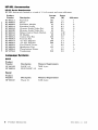
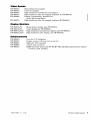
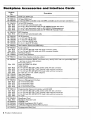
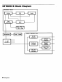
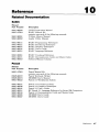
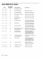
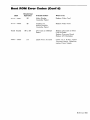
1
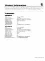
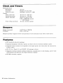
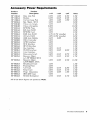
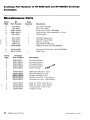
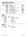
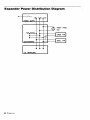
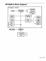
HP 9000 Series 300 Computers
r/i~ HEWLETT
a!~ PACKARD
98561AjB Service Handbook
98561 A/B Service Handbook
for HP 9000 Series 300 Computers
HP Part Number 98561-90039
., Copyright 1985,1986 Hewtett-Packard Company
This document contains proprietary informatIOn which is protected by copyright. AU rights are reserwd. No part of this document may be photocopied,
reproduced or translated to another language without the prior written consent of Hewlett-Packard Company. The information contained in this
document is subject to change without notice.
Restricted Rights Legend
Use, duplicatIOn or disclosure by the
Software clause in DAR 7-104.9(8)
~t
is subject to restrictions as set forth in paragraph (bK3KB) of the Rights in Technical Data and
Hewlett-Packard Company
3404 East Harmony Road, Fort Colin., Colorado 80525
Printing History
New editions of this manual will incorporate all material updated since the previous edition. Update
packages may be issued between editions and contain replacement and additional pages to be merged
into the manual by the user. Each updated page will be indicated by a revision date at the bottom of
the page. A vertical bar in the margin indicates the changes on each page. Note that pages which are
rearranged due to changes on a previous page are not considered revised.
The manual printing date and part number indicate its current edition. The printing date changes when
a new edition is printed. (Minor corrections and updates which are incorporated at reprint do not
cause the date to change.) The manual part number changes when extensive technical changes are
incorporated.
May 1985 ... Edition 1
March 1986 ... Edition 2
May 1986 ... Update
NOTICE
The information contatned In this document is subject to change without notice
HEWLETT·PACKARD MAKES NO WARRANTY OF ANY KIND WITH REGARD TO THIS MANUAL. INCLUDING. BUT NOT LIMITED TO. THE IMPLIED WARRANTIES
OF MERCHANTABILITY AND FITNESS FOR A PARTICULAR PURPOSE. Hewlett-Packard shall not be liable for errors contained herein or direct.
InCIdental or consequential damages in connection with the furnishing, performance, or use of this material
Ind~ect.
speoaJ.
WARRANTY
A copy of the specific warranty terms applicable to your Hewlett-Packard product and replacement parts can be obtained from your local Sales and ServICe Office
ii
98561-90039, rev: 5/86
Product Information
II
Environmental/Installation/PM
E
Configuration
Troubleshooting
Diagnostics
Adjustments
Peripherals
Replaceable Parts
Diagrams
Reference
Service Notes
•II
I
I
•I
11
II
I
Physical
Height:
Width:
Depth:
Weight:
Computer:
Expander:
Shipping Weight:
Computer:
Expander:
130 mm (5.12 inches)
325 mm (12.80 inches)
376 mm (14.80 inches)
10.57 Kg (23.25 lbs)
10.18 Kg (22.4 lbs)
15.91 Kg (35 lbs)
12.00 Kg (26.41 lbs)
Power Requirements
Operating voltage:
Operating frequency:
Power consumption:
Backplane power*:
85 to 129 Vac, 187 to 250 Vac
switch-selectable
48 to 66 Hz
250 W (maximum)
HP 98561A Computer
HP 98568A Expander
31 W @ +5 V
19.2 W @ +12 V
6 W@ -12 V
62 W @ +5 V
38.4 W @ +12 V
12 W @ -12 V
*Any card designed for installation in this backplane must meet DIO guidelines. DIO guidelines
may be found in the Accessory Development Guide, part number 09800-90010.
Product Information
3
Product Configuration
Product
Number
Description
HP 98561A
MC68010 processor
Low-resolution monochrome video output
1M bytes RAM
HP-IB, HP-HIL, RS-232 and audio interfaces
Battery-backed real-time clock
4-slot card cage for interfaces and memory
HP 46020A Keyboard
Option 002
Delete 512K bytes RAM
Option 003
Delete video controller
Option 004
Delete 4-slot card cage
HP 98561B
MC68020 processor
4-slot card cage for interfaces and memory
HP-IB, HP-HIL, RS-232 and audio interfaces
Battery-backed real-time clock
HP 98257 A RAM card (1 M byte)
HP 46020A Keyboard
4
Product Information
Product Information
1
Information in this manual refers to the HP 9000 HP 98561A and HP 98561B computers. Where
applicable, the information also applies to the HP 98568A eight-slot backplane expander.
Processors
HP98561A
Type:
Clock frequency:
Internal architecture:
Address range:
RAM data bus:
Instruction types:
Major data types:
Addressing modes:
Interrupt levels:
Motorola 68010
10 MHz
32-bit data and address registers
16M bytes (7.5M bytes user RAM)
16-bit asynchronous
57
5
14
6 maskable and 1 non-maskable
HP98561B
Type:
Clock frequency:
Internal architecture:
Address range:
RAM data bus:
Cache data bus:
Instruction types:
Major data types:
Addressing modes:
Interrupt levels:
Floating-point Co-proc.
Motorola 68020
16.6 MHz
32-bit data and address registers
4G bytes (7.5M bytes user RAM)
16-bit asynchronous
32-bit
100
7
18
6 maskable and 1 non-maskable
12.5 MHz Motorola 68881
Product Information 1
Clock and Timers
Real-time clock
Resolution:
Accuracy:
Power-on reset:
Timers
Delay interrupt:
Cycled interrupt:
Match interrupt:
Time of day and date:
10 msec
50 ppm (4.3 sec/day)
Midnight, January 1, 1900
10 msecs to 1.94 days
10 msecs to 1.94 days
Match on time of day,
0.00 to 84600.00 seconds
(23.5 hours)
10 msec, battery-backed
Beepers
Range (nominal):
Duration:
81.375 Hz to 5208 Hz
0.01 to 2.55 sec
Beeper hardware supports three tone generators with attenuators and white noise source.
Features
• HP standard industrial package
• Optional backplane with four option card slots (two for external interface cards)
• Optional direct-connect I/O expander with eight option card slots (four for external interface cards)
• HP-UX 5.0, Pascal 3.1 and BASIC 4.0 language systems
• Supports external 12-inch medium-resolution, monochrome or color display, and 17-inch
monochrome and 19-inch color high-resolution displays
• HP-HIL accessory support
2 Product Information
Accessory Power Requirements
Product
Number
HP l3264A
HP l3265A
HP l3266A
HP98028A
HP982D4B
HP982D4B
HP98253A
HP98254A
HP98255A
HP98256A
HP98257A
HP98259A
HP98620B
HP98622A
HP98623A
HP98624A
HP98625B
HP98626A
HP98627A
HP98628A
HP98629A
HP98629A
HP98630A
HP98635A
HP98640A
HP98644A
HP 9869lA
HP98695A
HP98642A
Product
Description
Data Link Pod
Modem
Current Loop Pod
Res. Mgmt. MUX
Video ,v/o Graph.
Video w /Graphics
EPROM Prog.
64K byte RAM
EPROM Card
256K byte RAM
1M byte RAM
l28K byte Bubble
DMA Controller
GPIO Interface
BCD Interface
HP-IB Interface
Disc Interface
RS-232 Interface
Color Interface
Datacomm Interf.
Resource Mgmt.
w / 0 HP 98028A MUX
Resource Mgmt.
w /HP 98028A MUX
Breadboard Card
Floating-Point
A-D Card
Serial Card
Progr. Datacomm
IBM 3270 Coax
RS-232 Multiplexer
-12V
Total
0.2W
l.9W
0.3W
0.5W
0.5W
0.5W
1.OW
l.OW
1.OW
2.2W
6.4W
7.SW
l5.0W
5.7W
3.0W
2.8W
4.1 W (2.7W standby)
4.0W (4.0W standby)
2.4W
2.9W
6.0W
3.8W
2.5W
2.4W
3.0W
D.lW
2.0W
D.6W
D.6W
5.5W
3.6W
0.5W
0.7W
3.7W
D.5W
0.5W
+5V
2.4W
l.5W
3.0W
8.6W
7.5W
l5.0W
5.7W
3.0W
2.8W
4.lW
5.9W
l.3W
4.2W
2.6W
2.0W
6.4W
7.2W
5.7W
+12V
B.OW
5.3W
6.0W
3.8W
2.5W
2.4W
3.lW
3.2W
5.5W
4.8W
4.7W
O.5W
13.3W
D.7W
D.3W
2.0W
D.2W
D.lW
l.3W
0.8W
O.IW
1.3W
4.2W
3.5W
2.4W
9.7W
7.2W
6.6W
6.9W
All of the above figures are quoted in Watts.
Product Information
5
HP·HIL Accessories
HP-HIL Device Requirements
HP-HIL devices are limited to a total of 1 A of current and seven addresses.
Product
Number
HP46021A
HP46060A
HP46080A
HP46081A
HP46082A
HP46082B
HP46083A
HP46084A
HP46085A
HP46086A
HP46087A
HP46088A
HP46089A
HP46094A
HP46095A
HP 35723A
Description
Keyboard
Mouse
Extension Module
Extension/ Audio
15-metre Audio/Video Ext.
30-metre Audio/Video Ext.
Rotary Control Knob Module
ID Module
Control Dial Box
Function Box
"A" -Size Digitizer
"B" -Size Digitizer
Four-Button Cursor
Quadrature Port
Three-button Mouse
Touchscreen
Current
(ma)
100
200
25
25
50
50
110
60
320
80
200
200
0
125
0
2.50
Power
(W)
1.2
2.4
0.3
0.3
0.6
0.6
1.32
0.72
4.0
1.0
2.4
2.4
0.0
1.5
0.0
3.0
Addresses
1
1
0
0
0
0
1
3
1
0
1
0
Language Systems
BASIC
Product
Number
HP98613B
HP98603A
Description
BASIC 4.0
ROM BASIC 4.0
Memory Requirements
768K bytes
none
Description
Pascal 3.1
Memory Requirements
512K bytes
Pascal
Product
Number
HP98615C
6
Product Information
98561-90099, rev:
9/86
Video Boards
Monochrome bit-mapped
Color bit-mapped
High-resolution monochrome bit-mapped
High-resolution color bit-mapped (replaced by HP 98547 A)
Display Compatibility Interface for
Series 200 compatibility
High-resolution color bit-mapped (replaces HP 98545A)
HP98542A
HP98543A
HP98544A
HP98545A
HP98546A
HP98547A
Display Monitors
HP35731A/B
HP35741A/B
HP 98781A/B/C
HP 98782A/B/C
Monochrome display (use HP 98542A)
Color display(use HP 98543A)
High-resolution monochrome display (use HP 98544A)
High-resolution color display (use HP 98545A)
Enhancements
HP98242A
HP98567A
HP98568A
HP98569A
HP98243A
98561-90099, rev:
Four-slot I/O backplane
Display monitor 19-inch rack-mount kit
Eight-slot I/O expander
19-inch rack-mount kit
68020 processor board and HP-IB/HP-HIL/RS-232/audio/battery-backed
real-time clock interface
9/86
Product Information
7
Backplane Accessories and Interface Cards
Product
No.
Description
HP98256A
256K byte RAM Card
HP98257A
HP98620B
1M byte RAM Card
2-channel DMA Controller (only one DMA controller can be used per mainframe)
HP98622A
(Opt. 001)
(Opt. 002)
(Opt. 003)
(Opt. 004)
16-bit GPIO Interface
4.6 m (15 feet) unterminated cable
0.8 m (2.5 feet) terminated cable for HP 9885M Flexible Disc Drive
4.6 m (15 feet) terminated cable for HP 6940NB Multiprogrammer
2.5 m (8.3 feet) terminated cable for HP 9866NB Thermal Printer
HP98623A
(Opt. 001)
BCD Interface
4.6 m (15 feet) unterminated cable
HP98624A
HP 10833A
HP 10833B
HP 10833C
HP 108330
HP-IB Interface
1 m (3.3 feet) HP-IB cable
2 m (6.6 feet) HP-IB cable
4 m (13.2 feet) HP-IB cable
0.5 m (1.6 feet) HP-IB cable
HP98625A
Disc Interface (Pascal and SRM only)
HP98626A
(Opt. 001)
(Opt. 002)
HP 13265A
HP 13266A
Serial Interface
4.9 m (16 feet) RS-232 cable with DTE connector (male)
4.9 m (16 feet) RS-232 cable with DCE connector (female)
300 Baud Modem
Current Loop Interface
HP98627A
Color Video Interface (includes cables)
HP98628A
(Opt. 001)
(Opt. 002)
(Opt. 003)
(Opt. 099)
HP 13264A
HP 13265A
HP 13266A
Datacomm Interface (BASIC and Pascal only. Always order with one personality option
and one or more cable options)
Personality Options
Async and Data Link ROM
Cable Options
4.9 m (16 feet) RS-232-C DTE (male) cable with test connector
4.9 m (16 feet) RS-232-C DCE (female) cable with test connector
4.9 m (16 feet) RS-449/423 DTE (male) cable with test connector
No cable (for use with 1326X adapters)
Data Link Adaptor
300 Baud Modem
Current Loop Interface
HP98629A
(Opt. 001)
(Opt. 002)
(Opt. 003)
(Opt. 004)
Resource Management Interface
10 m terminated cable
25 m terminated cable
60 m terminated cable
60 m unterminated cable
HP 98691A
(Opt. 001)
(Opt. 002)
(Opt. 003)
(Opt. 099)
Programmable Datacomm Interface with 4K RAM
4.9 m (16 feet) RS-232-C DTE (male) cable with test connector
4.9 m (16 feet) RS-232-C DCE (female) cable with test connector
4.9 m (16 feet) RS-449/423 DTE (male) cable with test connector
No cable
HP98630A
(Opt. 001)
HP98255A
HP98253A
HP98259A
Breadboard Card
Backplane Extender Card
EPROM Card
EPROM Development Kit (2 cards)
128K Byte Magnetic Bubble Memory Card
HP98635A
Floating-point Math Card
(Opt. 100)
8 Product Information
Tools List
The following tools are needed to service HP 98561A/B computers and the HP 98568A expander:
Part Number
9300-0933
3476B
Description
Standard CE Tool Kit
Anti-static workstation
Multimeter
Product Information 9
~~
Top Cover
, "~_
Power
Supply Door
~
m
Power
Supply
:.
0-
"
A.
CD
A.
<
i"
E
Front Panel
Address Information
Decimal Approx.
Hex
F'FFFFF
18M-1
Ram
16M Byte.
9M
8M
T_/Monltor
txt.nal
I/O
IntemoI
I/O
6M
4M
900000
800000
600000
400000
Syam ROM
258K
1K
o
IIootI
ElIoeptIon Tallie
oo3FFf'
000400
000000
Series 300 Memory Map
W." W"""" "1.11"" ••• 7 ••• 1.1
I/O Regl.ter Select
standard Select Code.
External
I/O
------1
600000
Internal
8M ......
4M ....._ _ I/O
_ _ _..J 400000
Memory--Mapped I/O
12 Product Information
o 11M
UtH
I
2K't'IDatCUC
~ GraphIoe
I
~
:.t.mepped """"
....
[IItIrMI
....."...
8M . . . - - - - - . . . . , 800000
••
10
II
12
13
14
1IS232
20
o.tG
c.mm
BCD
GPIO
DIM Jntrfc.
External Address Format
3,.
Environmental/Installation/PM
2
Environmental Range
Operating Temperature:
O°C to 55°C (32°F to 131°F)
Humidity:
5% to 95% R.H. non-condensing, 40°C (104°F) maximum wet-bulb temperature
Storage Temperature:
-40°C to 75°C (-40°F to 197°F)
Maximum Altitude:
4600 metres (15 000 feet)
EMI:
Conducted and radiated interference meets VDE Level
A standards.
Conducted and radiated interference also meets FCC
class A standards, although some individual Series 300
products may meet FCC class B standards. Check the
FCC label on the rear panel.
Line Transient Spike Immunity:
1 kV (1 nsec. rise, 800 nsec. duration)
Additional Regulatory COmpliance:
UL, CSA, IEC
These specifications apply to HP 98561A/B computers and the HP 98568A expander, but not
necessarily to any peripheral (including display monitors).
Installation
The Model HP 98561A and HP 98561B computers are customer-installable, unless a noncustomer-installable peripheral is included in the order. The Model HP 98568A expander is
likewise customer-install able.
Mounting
Tabouret or mini-rack, or unmounted (desktop).
Cabling
Standard HP-IB, HP-HIL.
RS-232-C:
25-pin on HP 98561A
9-pin on HP 98561B
9-pin:
HP 92221M DTE to DCE
HP 92221P DTE to DTE
HP 92222F female to female gender converter
HP 92222W custom wiring kit
98561·90099, rell: 5/86
Environmental/Installation/PM
13
Setting Processor Board Switches
HP 98561A processor boards contain communications functions with switch-selected attributes.
This section tells how to set the switches for desired operation. HP 98561B processor boards do
not contain any switches.
RS·232 Control Una Defeat:
o
Control lines defeated
Control lines enabled (default)
This function enables or defeats the DCD, CTS, DSR and RI control lines.
RS·232 Keyboard:
o
Local keyboard (default)
Remote keyboard
Display Disable:
o
On-board video enabled (default)
On-board video disabled
HP·IS System Controller:
o
Computer is not system controller (HP-IB address 20)
Computer is system controller (HP-IB address 21) (default)
14 Environmental/Installation/PM
Processor Board Switch Chart
RS-232 Control Une
RS-232 Keyboard
Display Disable
HP-IB System
Environmental/lnstallation/P~1
15
Setting Human Interface Card Switches
The 98561-66530 human interface card contains communications functions with switch-selected
attributes. This section tells how to set the switches for desired operation.
RS-232 Control Line Defeat:
o
Control lines defeated
Control lines enabled (default)
This function enables or defeats the DCD, CTS, DSR and RI control lines.
RS-232 Keyboard:
o
Local keyboard (default)
Remote keyboard
HP-IB System Controller:
o
Computer is not system controller (HP-IB address 20)
Computer is system controller (HP-IB address 21) (default)
16 Environmental/Installation/PM
Human Interface Card Switch Chart
/
i
5_232 Control Une
R5-232 Keyboard
Unused
_HP-IB_m
D/
o
III
Environmental/Installation/PM 17
·
AM Starting Address
Setting the R
1M Byte Cards
256K Byte Cards
~
~
~
~
~
~
~
First Card
~
o
0 0 0
Second Card
Third Card
Fourth Card
Fifth Card
Sixth Card
Seventh Card
18 Environmental/Installation/PM
~
[!!
~
[!§J
~
~
AI...., ....0I1ed
on HP 985618
Preventive Maintenance
The real-time clock contains a lithium battery which should be replaced once a year.
real-time clock is located according to this chart:
Model
Option
Location
HP98561A
000
002
003
98561-66512
98561-66511
98561-66513
Processor Board
Processor Board
Processor Board
HP98561B
All
98561-66530
Human Interface Card
The
Although the battery is available from Hewlett-Packard, it is usually can he obtained locally.
It is a 3V, 160mAH battery from these manufacturers:
Manufacturer
Part Number
Panasonic
BR2325
WARNING
Battery may explode if mistreated. Do not recharge, disassemble or
dispose of in fire.
When changing the battery, relllember that the real-time clock will reset to its default state,
and it is necessary to set it to the current time. Note also that the battery retainer clip is a
conductor, and merely lifting it up without changing the battery will still cause the real-ti~H'
clock to reset.
Environmcntal/Installation/P!\1 19
Notes
20 Environmental/Installation/PM
3
Configuration
System Products
Here's a description of the systems which customers will order.
follows.
A drawing of each system
Component
HP98580A
HP98581A
HP98582A
HP98583A
Computer
HP98561A
HP98561A
Option 003
HP98561B
HP98561B
none
none
1M
HP98257A
1M
HP98257A
Monochrome
HP 35731A/B/C
Color
HP 35741A/B/C
Hi-res mono
HP 98781A/B/C
Hi-res color
HP 98782A/B/C
Monochrome
on processor
Color
HP98543A
Hi-res mono
HP98544A
Hi-res color
HP98547A
3
4
2
8
HP98568A
ROM BASIC
HP98613B
none
none
Speaker Module
HP46081A
RAM
Monitor
Video Output
DIO Slots
Extras
disc interf. HP 98625B
DMA card HP 98620B
Options
002:
Delete 512K bytes RAM
98561-66511
008:
Add compatibility
interface HP 98546A
98561-90099, rev:
9/86
Add compatibility
Interface HP 98546A
Configuration
21
HP 98561 X Products
Here's a description of the boxes Manufacturing will build:
HP98561A
HP98561A
Option 002
Option 003
MC68010
98561-66512
MC68010
98561-66511
MC68010
98561-66513
MC68020
98561-66519
RAM
Internal
External
1M byte
none
512K byte
none
1M byte
none
none
1M byte
HP98257A
Video Output
on SPU
on SPU
none
none
Interfaces
on SPU
on SPU
on SPU
on Human Int. Cd.
98561-66530
Keyboard
HP-HIL
HP46020A
HP-HIL
HP46020A
HP-HIL
HP46020A
HP-HIL
HP46020A
DIO Slots
4
4
4
2
Delete backplane
98561-60001
Delete backplane
98561-60001
Delete backplane
98561-60001
none
Component
SPU
Option 004:
22
HP98561A
Configuration
HP98561B
HP 98580A Configuration
Monitor
HP-HIL Cable
k
HP 35731
A/B
board HP-HIL Cable
HP 98581A Configuration
Computer
HP 98561A
Option 003
Audio Cable
3-Conductor Video Cable
StraiGht HP-HIL Cable
Keyboard
HP 46020A
Monitor
HP 35741
A
Keyboard HP-HIL Cable
I
HP 98582A Configuration
Video Cable
Computer
HP 98561B
keyboard
HP 48020A
~
Monitor
HP 98781
Control/Audlo/HP-HIL Cable
keyboard HP-HIL Cable
A/B/C
I
HP 98583A Configuration
3-Conductor Video Cable
Computer
HP 98581B
Audio Cable
StraiGht HP-HIL Cable
Speaker
Module
HP 46081A
Monitor
HP 98782
A/B/C
Expander
HP 98581A
Keyboard
HP 46020A
Keyboard HP-HIL Cable
Configuration 23
Notes
24
Configuration
4
Troubleshooting
Initial Troubleshooting Flowchart
Reploce FUM.
Operate Computer.
Ve.
Refer to OeM
Unit Procedure
START A
Refer to Dead
Unit Procedure
START B
Refer to Live
Unit Procedure
Refer to Boot
ROM Error Coda
Troubleshooting 25
Dead Unit Troubleshooting Flowchart
26 Troubleshooting
Live Unit Troubleshooting Flowchart
Troubleshooting 27
Power Supply Specifications
Make sure that the computer is properly grounded. It requires a three-wire power cable and
the power supply retaining/grounding screw must be installed. Also, make sure that the power
supply access door is properly installed.
Voltage
Voltage Tolerance
and Ripple
Maximum
Current
-12 V
-11.86 to -12.72 V
1.1 A
+5 V
4.89 to 5.25 V
20 A
+12 V
11.86 to 12.72 V
3.6 A
Power Supply Test Points
Voltage
Test Point to Ground
Visual Indication
Other Indication
-12 V
Motherboard -12 V pin
Front Panel LED Lit
Small Fan Running
+5 V
Motherboard +5 V pin
Processor Board Test
LEDs Lit at power-up
Small Fan Running
+12 V
Motherboard + 12 V pin
Front Panel LED Lit
Large Fan Running
Power Supply Test Points
L
••••
»>~
Il1NNC
+.-.-::1
+ I 0
C5
I
J
Motherboard
(component side)
l
28 Troubleshooting
J
5
Diagnostics
Boot ROM Self Test Sequence
Test
LED display
....
CPU test 1
Top 16K RAM test
2
0.00
04
0000
0.0.
05
Alpha display controller
test (if present)
000 •
••• 0
IE
Bit-mapped display
controller test
000.
•• 0.
lD
000.
00.0
12
4
000.
00 • •
13
Boot ROM checksum test
0000
00 • •
03
Graphics display
controller test
000.
••••
IF
Internal HP-IB test
000.
0.00
14
DMA test
000 •
• 000
18
I/O card test
oo.X XXXX
ROM checksum test
0000
•• 0.
OD
RAM test
0000
.00.
09
3
Local keyboard test
or
Accessory keyboard test
1
3
4
FF
0000
CPU timer test
2
Hex equivalent
20 to 3F
Self test stops here and displays. 0 0 0 0 0 0 . (81 hexadecimal) on the LEDs if the CPU fails its test.
Self test stops here and displays 0 . 0 0 0 . 0 0 (44 hexadecimal) or . 0 0 0 0 . 0 0 (84) on the LEDs unless functional RAM
is present in the top 16K bytes of RAM space.
Self test stops here and displays 0000 0 . 0 . (05 hexadecimal) on the LEDs if the CPU board timer fails its test.
IT more than one accessory keyboards are present, only the one with the lowest select code will be checked.
Diagnostics
29
Boot ROM Error Codes
LEDs
Hexadecimal
Equivalent
Probable Failure
What to Do
0000
0000
00
No Failure Detected
0000
0.0.
05
CPU Timer Failed
Replace CPU Board
0.00
0.00
44
Top RAM Missing
Check RAM Addressing
0 •••
••••
7F
LEDs failed to DTACK
Replace Processor Board
• 000
000 •
81
CPU Failed
Replace Processor Board
• 000
00 • •
83
Boot ROM Failed
Checksum
Replace Processor Board
.000
0.00
84
Top RAM Failed
Check RAM Addressing
Replace Processor Board
.000
.00.
89
RAM Failure
Check RAM Addressing
Replace Processor Board
.000
.0.0
8A
Insufficient RAM
Check RAM Addressing
Replace Processor Board
.000
•• 0.
8D
ROM Operating System
Failed Checksum
Replace Processor Board
Replace I/O Connectorboard
.00.
00.0
92
Local Keyboard
Controller Failed
Replace Processor Board
(except 98561-66519
Processor Board, replace
Human Interface Card)
• 00.
00 • •
93
Accessory Keyboard
Controller Failed
Replace Accessory Keyboard
Controller
.00.
0.00
94
HP-IB Failed
Replace Processor Board
(except 98561-66519
Processor Board, replace
Human Interface Card)
.00 •
• 000
98
DMA Card Failed
Replace DMA Card
Replace Processor Board
.00.
• • 00
9C
Bit Map Font Failed
Replace Video Board
.00 •
•• 0.
9D
Bit Map Failed
Replace Video Board
30
Diagnostics
Boot ROM Error Codes (Cont'd)
Hexadecimal
Equivalent
Probable Failure
What to Do
.00 •
••• 0
9E
Alpha Display
Controller Failed
Replace Video Board
• 00.
••••
9F
Graphics on
Alpha/Graphics
Controller Failed
Replace Video Board
LEDs
.0XX XXXX
90 to BF
I/O Card at XXXXX
Failed
Replace I/O Card at Select
Code XXXXX
Replace Processor Board
Replace I/O Backplane
•••• ••••
FF
LEDs Never Accessed
Check -12 V. If okay, replace
Processor Board. Otherwise,
replace Power Supply.
Remote System Analysis
The Model HP 98561A/B computers provide for remote system analysis of problems by means
of the beeper. To diagnose the computer remotely, follow this procedure:
1. Establish a telephone connection with someone at the location of the computer.
2. Have them hold the receiver near the speaker output of the computer. The speaker is
located in 35731, 35741 and 98781 monitors, or in the speaker module.
3. Now have them turn the computer on.
4. The computer will go through its self test and report problems as a series of beeps. These
beeps correlate with the above error codes.
5. The beeper annunciates the seven least significant bits. A high beep indicates a one and
a low beep indicates a zero.
For example, suppose that on power-up a computer emits three low beeps, a high beep, two low
beeps and a high beep. This will be of the form:
Xo 0 0 .00.
(09 or 89 hexadecimal)
where 0 represents a low beep, • represents a high beep and X represents an unbeeped high or
low. Referring to the table of Boot ROM Error Codes leads us to RAM Failure as the probable
cause.
Diagnostics
31
Locating a Defective RAM Card
The RAM failure message may be decoded to determine which RAM card caused the failure.
For example, in the message
Memory Failed at FB53A9
W:F58A8C2C,R:F78A8C2C
the failure occured at memory address FB53A9. To correlate this with a RAM card, take the
first two letters or digits of the address and translate them into binary. Then find a card whose
address switches are set to the first four or six bits of that address.
For instance, in the above example, FB is • • •• •
the defective board would be:
0 ••
in binary. Therefore, the switches on
if a 1M byte card, or if a 256K hyte card.
If you are unable to find a memory card with the appropriate switch setting, the failure is in
RAM located on the processor board.
32
Diagnostics
Adjustments
6
There are no adjustments in the computer. For adjustments to the monitor, refer to the Service
Manual for the monitor.
Adjustments 33
Notes
34 Adjustments
Peripherals
7
Supported Peripherals List
Due to constant change of the list of supported peripherals, this information is published separately. The Series 300 Configuration Reference Manual (part number 98561-90020) has this
information.
Peripherals
35
Notes
36
Peripherals
8
Replacement Parts
The parts listed in this chapter apply to both the HP 98561A/B computer and the HP 98568A
eight-slot expander, unless noted otherwise.
Assemblies
HP 98561 A/B Assemblies
Description
Repair
Status
98561-66511
98561-66512
98561-66513
98561-66519
0950-1760
Processor Board
Processor Board
Processor Board
Processor Board
Power Supply
Exchange
Exchange
Exchange
Exchange
Exchange
6
3
1
8
3
98561-60001
09826-66524
98257-66524
98561-66530
98542-66570
Four-slot Backplane
256K Byte Memory Card
1M Byte Memory Card
Human Interface Card
B/W Vid. Bd.
Non-exchange
Exchange
Exchange
Exchange
Exchange
4
5
8
7
98543-66570
98544-66570
98547-66570
98546-66570
98204-66577
Medium-res Color Vid. Bd.
High-res B/W Vid. Bd.
High-res Color Vid. Bd.
Disp. Compo Interface
Graphics Card
Exchange
Exchange
Exchange
Exchange
Exchange
3
98561-66501
Motherboard
Non-exchange
Check
Digit
UP Part
Number
5
6
7
3
6
98561A Option
000 002 003 98561B
HP 98568A Assemblies
Check
Digit
UP Part
Number
9
98568-66500
98568-66501
0950-1760
o
6
98561-90099, 'ell: 9/86
Total
Quantity Description
Eight-slot Backplane
Motherboard
Power Supply
Repair
Status
Non-exchange
Non-exchange
Exchange
Replacement Parts
37
Exchange Part Numbers of HP 98561 A/B and HP 98568A Exchange
Assemblies
Miscellaneous Parts
Check
Digit
HP
Part Number
Total
Quantity
0
7
2
9
8
2110-0342
7101-0591
98561-04104
98561-04101
5001-9001
Line Fuse (6ANB)
I/O Cover Plate
Large Cover Plate, HP 98561
Cover Plate, Silk-screened for '19 bd.
LED Bracket
0
5
2
4
7
5041-1203
5041-2412
1420-0314
1420-1353
98546-84001
On/Off Pushbutton
On/Off Switch Shaft
Battery, Lithium
Clip, Battery Retainer
Softkey Overlay (for HP 98546A)
8
6
98546-84002
09817-47700
Numeric Pad Overlay (for HP 98546A)
Light Pipe
Description
Check
Digit
Exchange
Part Number
Description
1
2
3
9
98561-69511
98561-69512
98561-69513
98561-69519
98561-69553
Processor Board
Processor Board
Processor Board
Processor Board
Power Supply
9
7
4
9
0
09826-69524
98257-69524
256K Byte Memory Card
1M Byte Memory Card
Human Interface Card
Medium-res B/W Video Board
Medium-res Color Video Board
4
3
6
38
~~
~2-6 70,~
543~
98544-69570
98547-69570
98546-69570
98204-69577
Replacement Parts
~t.
~,\'\ 11°
High-res B/W Video Board
High-res Color Video Board
Compatibility Video Card
Graphics Card
98561-90099, rev: 9/86
Case Parts
Check
Digit
HP
Part Number
Total
Quantity
7
8
2
6
5
5001-3698
5001-3699
5001-3693
5041-2413
5180-1303
Top Cover, HP 98561
Top Cover, HP 98568
Fan Chassis
Front Panel
Fan, Small
4
5
6
9
5180-0410
3160-0481
5001-3696
5001-3697
09817-41200
Fan, Large
Fan Grill
Chassis, HP 98561
Chassis, HP 98568
Power Supply Guide
0
2
6
1
9
09817-41201
0403-0379
09121-48303
0403-0427
0380-1655
2
5001-3700
2
2
2
2
Description
I/O Card Guide
PC Board Guide, HP 98561
Front Foot
Rear Foot
Snap-in Spacer
Power Supply Door
Internal Cable Assemblies
Check
Digit
HP
Part Number
8
4
1
0
5
5180-0407
5180-1302
98568-6160 1
98568-61600
98561-61601
4
98561-61602
98561-90099, re,,:
9/86
Total
Quantity
1
2
Description
LED Cable
Fan Cable
Computer-to-expander cable
Dc Cable, HP 98568A
Short Ribbon Cable, HP 98561A/B
Long Ribbon Cable, HP 98561A/B
Replacement Parts
39
External Cable Assemblies
The assemblies listed in this section apply to the HP 98561A/B computer only.
Cheek
Digit
1
3
6
3
4
HP
Part Number
46020-60001
46080-61601
46083-61601
09920-61602
8120-3616
Description
HP-HIL Keyboard Cable, 3.0 m
HP-HIL Cable, 2.4 m
HP-HIL Cable, 0.5 m
Intf. Cable, aud/vid, 3.0 m
Color Cable, BNC-BNC, 1.5 m (3 needed)
Where Used
46020/46021 A
HIL
HIL
98544A
98543A
5
2
3
6
5061-6533
1252-1112
98561-61603
98561-61604
8120-4703
Video Cable, RCA-BNC, 2.4 m
Adapter, RCA-earphone
Dual Cable, RCA-RCA, 2.4 m
RS-232 Cable, DTE-DCE, 9-pin to 25-pin
Jumper Cable, BNC-RCA .. 75 m
98546A
98544/98547
98542/98561A
98561A
98546
7
6
7
8120-4704
8120-4712
98700-61603
Audio Cable, RCA-RCA, 2.4 m
Jumper Cable, BNC-BNC .. 75 m
Video Cable, BNC-BNC, 3.0 m
98543/98546
98546
98547
Labels
Check
Digit
HP
Part Number
7
4
6
5
98561-84002
98568-84002
5958-4325
7120-3428
9
9
8
0
7121-4858
7121-4733
7121-4857
7121-4859
0
98561-84005
Total
Quantity
Description
Identification Label, HP 98561
Identification Label. HP 98568
UL Info Label
CSA Label
1
1
2
Service Warning Label
Serial Label
Danger Label
Fuse Rating Label
Battery Warning Label
Screws
Check
Digit
6
0
40
HP
Part Number
Total
Quantity
0515-0219
0515-1146
Replacement Parts
8
7
Description
M3XO.5 Flathead Screw
M3X6 Panhead Screw
98561-90099, ret/: 51
n
Power Supply Door ~
5001-3700
~ . )
o
:I
-a
c
~
Top Cover
...
5001-3698~/~, [j
Four-Slot Backplane
98561-66500
Front Panel
5041-2413
'~"
//
CD
m
>C
-a
-~::s8S=:~
0'
On-Off Switch Shaft
5041-2412
D-
CD
D-
<
il
On-Off Pushbutton
5041-1203
Card Cage Brace
5001··3694 (shown)
5001-3695 (other side)
Chassis
5001-3696
Large Fan
5180-0410
---_...J.
3160-0481
•
Top Cover
5001-3699
V/
"'
Power Supply Door
5001-3700
>(
"
I»
:I
A.
CD
..
/~
Front Panel
5041-2413
"'
"0>(
0515-0389
A.
CD
A.
98568-61600
On-Off Switch Shaft
5041-2412
98568-61601
On-Off Pushbutton
5041-1203
Card Cage Brace
5001-3694 (shown)
5001-3695 (other side)
<
il
•
9
Diagrams
Computer Power Distribution Diagram
Ac
~
+5V +12V -12V
U
u
t~
POWER SUPPLY
PROCESSOR
,""'NT P
BOARD
~EL
LED
VIDEO
BOARD
TEST POINTS
-...-
9
-
MOTHERBOARD
0
4~
~ lARGE
fAN
I SMAI..l.
fAN
I
I
0
I/O BACKPLANE
Diagrams 43
Expander Power Distribution Diagram
,...
+~~
+ 7Y'
T12V
POWER SUPPLY
@
FRONT PAN EL
LED
Test_ Points
--
.~
I
MOTHERBOARD
4
I/O EW:KPlANE
44 Diagrams
J LAAGE
4
4
FAN
SMALL FAN
I
I
HP 98561 A Block Diagram
Processor Boord
I/O
IacIcpIane 1 - - - OptIon 004:
DIIete
Diagrams 45
HP 98561 B Block Diagram
Proce.80r Board
Human Interface Card
4-510t
Backplane
46 Diagrams
Peripheral
ProcH.or
10
Reference
Related Documentation
BASIC
Manual
Part Number
Description
98613-90091
98613-90092
CSUB Preparation Manual
BASIC Manual Kit
contains one each of the following manuals:
Utilities Library Manual
Loader Utility Manual
98613-90011
98613-90021
98613-90031
98613-90041
98613-90051
BASIC
BASIC
BASIC
BASIC
BASIC
98613-90061
98613-90071
98613-90082
BASIC Condensed Reference
BASIC Documentation Guide and Master Index
Software/Manual Catalog
98613-90090
98613-87904
Programming Techniques
Interfacing Techniques
Graphics Techniques
User's Guide
Language Reference
Pascal
Manual
Part Number
Description
09826-90072
09826-90073
98615-90022
Pascal Manual Kit
contains one each of the following manuals:
Pascal Textbook (Wiley)
MC68000 User's Manual
Pascal 3.1 Workstation System
98615-90031
98615-90036
98615-90041
98615-90051
98615-90016
98615-90606
98615-90607
Pascal 3.1 Procedure Library
Pascal 3.1 Graphics Techniques
Pascal 3.1 User's Guide
HP Pascal 3.1 Language Reference for Series 200 Computers
Pascal 3.1 Documentation Guide and Master Index
MC68020 User's Guide
MC68881 User's Guide
98615-87903
Reference
47
Service Documentation
Manual
Part Number
Description
98561-90000
98560-90601
98560-90602
98560-90603
98560-90604
Installation Reference
HP 98580A Installation
HP 98581A Installation
HP 98582A Installation
HP 98583A Installation
5958-4342
98546-90600
98242-90600
98243-90600
98568-90600
Upgrade Video Board Installation Note
HP 98546A Display Compatibility Interface Installation Note
HP 98242A Four-slot Backplane Installation Note
HP 98243A Upgrade Processor Installation Note
HP 98568A Eight-slot Expander Installation Note
5958-4343
5958-4344
98561-90030
98561-90039
HP 98569A Rack-mount Kit Installation Note
HP 98567 A Monitor Rack-mount Kit Installation Note
Service Information Manual
Service Handbook
Card
Card
Card
Card
Miscellaneous
Manual
Part Number
Description
98257-90000
98620-90001
98622-90000
98623-90000
98624-90000
HP 98256A/HP 98257 A RAM Card Installation Note
HP 98620B DMA Card Installation Note
HP 98622A GPIO Installation Manual
HP 98623A BCD Installation Note
HP 98624A HP-IB Installation Note
98625-90000
98626-90000
98627-90000
98628-90001
98630-90001
HP 98625A Disc Interface Installation Manual
HP 98626A RS-232 Installation Manual
HP 98627 A Color Video Interface Installation Manual
HP 98628/98691 Datacomm Installation Manual
HP 98630A Breadboard Installation Manual
98635-90001
HP 98635A Floating-Point Math Card Installation Note
48
Reference
Boot ROM Self Test Sequence
LED display
Hex equivalent
CPU test l
•••• ••••
FF
Top 16K RAM test 2
0000
0.00
04
CPU timer test
0000
o.oe
05
Alpha display controller
test (if present)
000 •
••• 0
IE
Bit-mapped display
controller test
000.
•• 0.
lD
000.
00.0
12
4
000.
00 • •
13
Boot ROM checksum test
0000
00 • •
03
Graphics display
controller test
000.
••••
IF
Internal HP-IB test
000.
0.00
14
DMA test
000.
.000
18
I/O card test
oo.X XXXX
ROM checksum test
0000
•• 0.
OD
RAM test
0000
.00.
09
Test
3
Local keyboard test
or
Accessory keyboard test
1
2
3
4
20 to 3F
Self test stops here and displays. 000 0 0 0 . (81 hexadecimal) on the LEDs if the CPU fails its test.
Self test stops here and displays 0 . 0 0 0 . 0 0 (44 hexadecimal) or . 0 0 0 0 . 0 0 (84) on the LEDs unless functional RAM
is present in the top 16K bytes of RAM space.
Self test stops here and displays 0000 0 . 0 . (05 hexadecimal) on the LEDs if the CPU board timer fails its test.
If more than one accessory keyboards are present, only the one with the lowest select code will be checked.
Reference
49
Boot ROM Error Codes
LEDs
Hexadecimal
Equivalent
Probable Failure
What to Do
0000
0000
00
No Failure Detected
0000
0.0.
05
CPU Timer Failed
Replace CPU Board
0.00
0.00
44
Top RAM Missing
Check RAM Addressing
0 •••
••••
7F
LEDs failed to DTACK
Replace Processor Board
• 000
000 •
81
CPU Failed
Replace Processor Board
.000
00 • •
83
Boot ROM Failed
Checksum
Replace Processor Board
.000
0.00
84
Top RAM Failed
Check RAM Addressing
Replace Processor Board
.000
.00.
89
RAM Failure
Check RAM Addressing
Replace Processor Board
.000
.0.0
8A
Insufficient RAM
Check RAM Addressing
Replace Processor Board
• 000
•• 0 •
8D
ROM Operating System
Failed Checksum
Replace Processor Board
Replace I/O Connectorboard
.00.
00.0
92
Local Keyboard
Controller Failed
Replace Processor Board
(except 98561-66519
Processor Board, replace
Human Interface Card)
• 00.
00 • •
93
Accessory Keyboard
Controller Failed
Replace Accessory Keyboard
Controller
.00.
0.00
94
HP-IB Failed
Replace Processor Board
(except 98561-66519
Processor Board, replace
Human Interface Card)
.00 •
• 000
98
DMA Card Failed
Replace DMA Card
Replace Processor Board
.00.
• • 00
9C
Bit Map Font Failed
Replace Video Card
.00 •
•• 0.
9D
Bit Map Failed
Replace Video Card
50
Reference
Boot ROM Error Codes (Cont'd)
Hexadecimal
Equivalent
Probable Failure
What to Do
.00 •
••• 0
9E
Alpha Display
Controller Failed
Replace Video Card
.00 •
••••
9F
Graphics on
Alpha/Graphics
Controller Failed
Replace Video Card
LEDs
.0XX XXXX
90 to BF
I/O Card at XXXXX
Failed
Replace I/O Card at Select
Code XXXXX
Replace Proce;ssur Buard
Replace I/O Backplane
•••• ••••
FF
LEDs Never Accessed
Check -12 V. If okay, replace
Processur Board. Otherwise,
replace Power Supply.
Reference 51
Notes
52 Reference
Service Notes
11
Sf'fvicf' Notf'S 53
Flin-
HEWLETT
~~ PACKARD
HP Part Number
98561-90039
Microfiche No. 98561-99039
Required Binder No. 9282-0683
Printed in U.S.A. 3/86
111111111111111111
98561-90608
For Internal Use Only