1
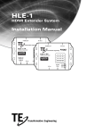
Monitor 50/EU
CONNECTION DIAGRAM
Fence terminator
10 Way connector of Monitor 50/EU
10
H.V. in from fence terminator
From Fence
9
8
Internal relay contacts
Normally Open
AUX
7
6
Closed circuit contacts
For Auxiliary/ Gate magnet set
Route separately from H.V. cables.
5
4
+12V SIREN
3
+12V STROBE
2
1
+
NEGATIVE (-)
12V 10W SIREN
To Float
Charger
+12V
12V BATTERY
STROBE LIGHT
++
-
-
MEPS Monitor 50/EU.
MEPS Monitor 50/EU.
Please refer to connection diagram for correct wiring.
MONITOR 50/EU Operater’s manual.
The monitor 50/EU is used to monitor the return voltage from the electric fence. The monitor can
measure high voltage return pulses of up to 15 Kilo-volts (15 000 Volts).
The MEPS Monitor 50/EU incorporates sophisticated digital design. Some of the features are as
follows:
1: DSP Technology (Digital signal processing) An on-board micro-processor calculates
the time between the high voltage pulses, and determines whether or not, to signal an
alarm condition. DSP technology reduces the chance of false alarms.
2: OPTO-Isolation technology. The components at the high-voltage side of the Monitor
50/EU, are optically isolated from the rest of the digital, and highly sensitive
components. This means that the high voltage, and low voltage areas on the printed
circuit board are isolated, by making use of infra-red technology.
3: LED Bar graph display. 10 x 5mm. Diffused LED’s are used to indicate the return
power from the fence. This return power is displayed in percentage form, from 10% up
to 100%. The LED’s are visible from the front view, of the Monitor 50/EU.
4: Auxiliary function. This function can be used to connect any external device, which
have a current / potential free switching contact. Thus, any door / magnetic, or even a
P.I.R. such as those used together with home alarm systems can be used to trigger the
siren, if connected to the system.
5: DRY contacts. There are two contacts provided on the Monitor 50/EU. These two
contacts are current / potential free. Meaning that no voltage, or current is available
at these two contacts, giving the user the opportunity to connect any external 3rd
party devices to the Monitor 50/EU. I.e. Armed response, telemetry systems, etc.
6: Siren output. This output can drive high external loads, up to 1,5 Ampere. The output
is designed for a 13,8 volt DC siren, for audible warning.
7: Strobe output. The Strobe output is intentionally designed for a load of 13,8 volt DC,
and a current rating of up to 1,5 Amperes. Any visible flashing device can be
connected to this output, provided that the current, and voltage ratings are not
exceeded. The Strobe output is intended for a visual warning. The MEPS red flasher
lamp can be connected to this output, to provide a bright “XENON” flash. The Strobe
output is very useful for a visible caution sign, if the premises was left, and the user
later returns, he/she will be able to be cautious, when entering the premises.
8: The module is not designed to be mounted directly onto a high voltage powered metal
surface e.g. directly onto a shock box. The module should therefore be mounted in an
isolated enclosure as been sold.
MONITOR 50/EU Connection diagram.