1
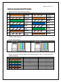
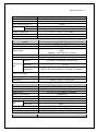
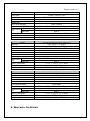
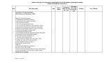
Release Version 1.0 How to connect the UTP cable 4Pairs of UTP cable Wiring System NO SeeEyes TIA / EIA 568B White & Orange 1 Orange 2 White & Orange Orange 3 Green White & Green 4 White & Green Blue 5 Blue White & Blue 6 White & Blue Green 7 Brown White & Brown White & Brown Brown Please note that the SeeEyes UTP cable wiring method is different from TIA/EIA 568B method. 8 RJ-45 JACK Wiring SeeEyes TIA / EIA 568B Please note that SeeEyes RJ-45 Wiring method is different from TIA/EIA 568B. When using the Junction Box (UTP power supply unit), connect the UTP cable as below. Cable # 1 2 3 4 5 6 7 8 Camera VIDEO (+) VIDEO (-) RS-485 (+) RS-485 (-) CAMERA POWER CAMERA POWER CAMERA POWER CAMERA POWER (+) (+) (-) (-) Receiver or DVR CAMERA 1 (+) CAMERA 1 (-) CAMERA 2 (+) CAMERA 2 (-) CAMERA 3 (+) CAMERA 3 (-) CAMERA 4 (+) CAMERA 4 (-)