1
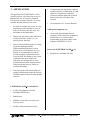
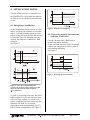
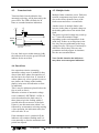
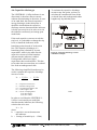
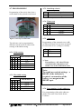
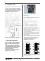
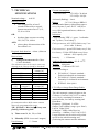
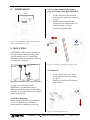
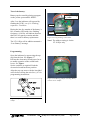
5. MAINTENANCE It is advisable to inspect the indicator once a year or 1 year after it was last activated. The inspection should include a functional test with a magnet to show that the flash frequency and intensity is normal. 5.1. Battery replacement The battery is fitted into the top cap of the indicator housing. To replace the battery, first disconnect the battery from the electronics board by pulling the battery plug, then pull the battery from the top cap. Fitting a new battery is the reverse of removing. The spare battery, KBB-11, comes with a connector so the replacement can be carried out on-site. Figure 11b. Location of soldering pads for resetting battery counter. Note! LT-110Eµr has the pads on the back side of the PCB, see fig 19, page 14. 2009 To activate the reset, the battery must be disconnected and connected again. The indicator has now reset the battery monitoring. 6. INDICATOR HOUSING The indicator housing is made of high strength plastics. The material is highly UV stabilised and is flame retarding. The lens material, in addition, has excellent optical characteristics. An O-ring with silicon grease joint is used to provide a good seal between the upper cap and the lens. The line clamp is made of PA (Poly Amid). Figure 10: LineTroll 110Eµ connectors 5.2. Reset battery monitoring The top cap of the indicator has a colourcoded label indicating the year of manufacture. See Figure 11 . When the battery is replaced with a new battery the battery monitoring must be reset. This is done by short-circuiting the two pads on the underside of PCB while at the same time powering the indicator by connecting the battery. The indicator will now confirm with continuous green flashing. Figure 11: Top-cap colour coding versus the year of manufacture LINETROLL 110E /110Eµr User Guide February 2010 Page 11 of 16