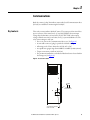
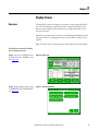
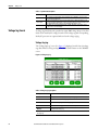
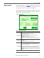
1
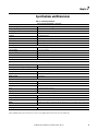
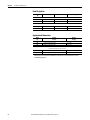
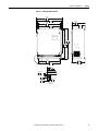
User Manual Bulletin 1608P ProDySC Dynamic Voltage Sag Corrector Catalog Numbers 1608P - 25 and 50 Amp Models Important User Information Solid-state equipment has operational characteristics differing from those of electromechanical equipment. Safety Guidelines for the Application, Installation and Maintenance of Solid State Controls (publication SGI-1.1 available from your local Rockwell Automation sales office or online at http://www.rockwellautomation.com/literature/) describes some important differences between solid-state equipment and hard-wired electromechanical devices. Because of this difference, and also because of the wide variety of uses for solid-state equipment, all persons responsible for applying this equipment must satisfy themselves that each intended application of this equipment is acceptable. In no event will Rockwell Automation, Inc. be responsible or liable for indirect or consequential damages resulting from the use or application of this equipment. The examples and diagrams in this manual are included solely for illustrative purposes. Because of the many variables and requirements associated with any particular installation, Rockwell Automation, Inc. cannot assume responsibility or liability for actual use based on the examples and diagrams. No patent liability is assumed by Rockwell Automation, Inc. with respect to use of information, circuits, equipment, or software described in this manual. Reproduction of the contents of this manual, in whole or in part, without written permission of Rockwell Automation, Inc., is prohibited. Throughout this manual, when necessary, we use notes to make you aware of safety considerations. WARNING: Identifies information about practices or circumstances that can cause an explosion in a hazardous environment, which may lead to personal injury or death, property damage, or economic loss. ATTENTION: Identifies information about practices or circumstances that can lead to personal injury or death, property damage, or economic loss. Attentions help you identify a hazard, avoid a hazard, and recognize the consequence. SHOCK HAZARD: Labels may be on or inside the equipment, for example, a drive or motor, to alert people that dangerous voltage may be present. BURN HAZARD: Labels may be on or inside the equipment, for example, a drive or motor, to alert people that surfaces may reach dangerous temperatures. IMPORTANT Identifies information that is critical for successful application and understanding of the product. ProDySC, Allen-Bradley, Rockwell Software, Rockwell Automation, and TechConnect are trademarks of Rockwell Automation, Inc. Trademarks not belonging to Rockwell Automation are property of their respective companies. Additional Resources These documents contain additional information concerning related products from Rockwell Automation. Resource Description Industrial Automation Wiring and Grounding Guidelines, publication 1770-4.1 Provides general guidelines for installing a Rockwell Automation industrial system. Product Certifications website, http://www.ab.com Provides declarations of conformity, certificates, and other certification details. You can view or download publications at http:/www.rockwellautomation.com/literature/. To order paper copies of technical documentation, contact your local Allen-Bradley distributor or Rockwell Automation sales representative. Table of Contents Ch 1 - Introduction Ch 2 - Installation Ch 3 - Communications Ch 4 - Applying Power Ch 5 - Display Screen Ch 6 - Maintenance Ch 7 - Specifications and Dimensions Important User Information . . . . . . . . . . . . . . . . . . . . . . . . . . . . . . . . . . . . . . . 2 Additional Resources . . . . . . . . . . . . . . . . . . . . . . . . . . . . . . . . . . . . . . . . . . . . . . 2 Safety Considerations . . . . . . . . . . . . . . . . . . . . . . . . . . . . . . . . . . . . . . . . . . . . . . 5 Installation Check List . . . . . . . . . . . . . . . . . . . . . . . . . . . . . . . . . . . . . . . . . . . . . 7 Inspecting and Unpacking . . . . . . . . . . . . . . . . . . . . . . . . . . . . . . . . . . . . . . . . . . 7 Location (Environment) . . . . . . . . . . . . . . . . . . . . . . . . . . . . . . . . . . . . . . . . . . . 7 Mounting Considerations . . . . . . . . . . . . . . . . . . . . . . . . . . . . . . . . . . . . . . . . . . 7 Mounting the ProDySC . . . . . . . . . . . . . . . . . . . . . . . . . . . . . . . . . . . . . . . . . . . 8 Bypass Switch . . . . . . . . . . . . . . . . . . . . . . . . . . . . . . . . . . . . . . . . . . . . . . . . . . . . 10 Bypass Switch Modes . . . . . . . . . . . . . . . . . . . . . . . . . . . . . . . . . . . . . . . . . . . . . 10 Bypass SwitchWiring Diagram . . . . . . . . . . . . . . . . . . . . . . . . . . . . . . . . . . . . . 11 Circuit Breaker Recommendations . . . . . . . . . . . . . . . . . . . . . . . . . . . . . . . . . 11 Accessing ProDySC Terminations . . . . . . . . . . . . . . . . . . . . . . . . . . . . . . . . . 11 ProDySC Terminations and Ratings . . . . . . . . . . . . . . . . . . . . . . . . . . . . . . . 12 Input: . . . . . . . . . . . . . . . . . . . . . . . . . . . . . . . . . . . . . . . . . . . . . . . . . . . . . . . . 12 Output: . . . . . . . . . . . . . . . . . . . . . . . . . . . . . . . . . . . . . . . . . . . . . . . . . . . . . . 12 Dry Contacts . . . . . . . . . . . . . . . . . . . . . . . . . . . . . . . . . . . . . . . . . . . . . . . . . . . . . 15 Serial Communications Port . . . . . . . . . . . . . . . . . . . . . . . . . . . . . . . . . . . . . . . 16 Overview . . . . . . . . . . . . . . . . . . . . . . . . . . . . . . . . . . . . . . . . . . . . . . . . . . . . . . . . 19 Home Screen . . . . . . . . . . . . . . . . . . . . . . . . . . . . . . . . . . . . . . . . . . . . . . . . . . . . . 21 System Status . . . . . . . . . . . . . . . . . . . . . . . . . . . . . . . . . . . . . . . . . . . . . . . . . . . . . 21 Voltage Sag Events . . . . . . . . . . . . . . . . . . . . . . . . . . . . . . . . . . . . . . . . . . . . . . . 22 Voltage Sag Log . . . . . . . . . . . . . . . . . . . . . . . . . . . . . . . . . . . . . . . . . . . . . . . . . . 22 Voltage Sag Detail . . . . . . . . . . . . . . . . . . . . . . . . . . . . . . . . . . . . . . . . . . . . . . . . 23 Voltage Sag RMS Voltage Charts . . . . . . . . . . . . . . . . . . . . . . . . . . . . . . . . . . 24 Voltage Sag Notification . . . . . . . . . . . . . . . . . . . . . . . . . . . . . . . . . . . . . . . . . . 24 System Events . . . . . . . . . . . . . . . . . . . . . . . . . . . . . . . . . . . . . . . . . . . . . . . . . . . . 25 System Event Log . . . . . . . . . . . . . . . . . . . . . . . . . . . . . . . . . . . . . . . . . . . . . . . . . 25 System Event Detail . . . . . . . . . . . . . . . . . . . . . . . . . . . . . . . . . . . . . . . . . . . . . . 26 System Event Notification . . . . . . . . . . . . . . . . . . . . . . . . . . . . . . . . . . . . . . . . . 27 System Configuration . . . . . . . . . . . . . . . . . . . . . . . . . . . . . . . . . . . . . . . . . . . . . 28 Model Information . . . . . . . . . . . . . . . . . . . . . . . . . . . . . . . . . . . . . . . . . . . . . . . 28 Run System Tests . . . . . . . . . . . . . . . . . . . . . . . . . . . . . . . . . . . . . . . . . . . . . . . . 29 Diagnostics Mode . . . . . . . . . . . . . . . . . . . . . . . . . . . . . . . . . . . . . . . . . . . . . . . . 29 Preventative Maintenance . . . . . . . . . . . . . . . . . . . . . . . . . . . . . . . . . . . . . . . . 31 Monthly Checks . . . . . . . . . . . . . . . . . . . . . . . . . . . . . . . . . . . . . . . . . . . . . . 31 3-6 Month Checks . . . . . . . . . . . . . . . . . . . . . . . . . . . . . . . . . . . . . . . . . . . . 31 System Event . . . . . . . . . . . . . . . . . . . . . . . . . . . . . . . . . . . . . . . . . . . . . . . . . . . . . 32 Fuse Replacement . . . . . . . . . . . . . . . . . . . . . . . . . . . . . . . . . . . . . . . . . . . . . . . . 33 Fuse Rating Charts . . . . . . . . . . . . . . . . . . . . . . . . . . . . . . . . . . . . . . . . . . . . . . . 34 Technical Specifications . . . . . . . . . . . . . . . . . . . . . . . . . . . . . . . . . . . . . . . . . . . 35 Heat Dissipation . . . . . . . . . . . . . . . . . . . . . . . . . . . . . . . . . . . . . . . . . . . . . . . . . 36 Approximate Dimensions . . . . . . . . . . . . . . . . . . . . . . . . . . . . . . . . . . . . . . . . . 36 Rockwell Automation Publication 1608P-UM001A-EN-P - July 2013 3 Table of Contents Notes: 4 Rockwell Automation Publication 1608P-UM001A-EN-P - July 2013 Chapter 1 Introduction The Allen-Bradley Bulletin 1608P ProDySC Dynamic Sag Corrector is engineered to provide years of trouble-free voltage sag (dip) protection. The patented ProDySC technology does not use batteries, requires only routine maintenance, includes three-stage transient voltage surge suppression, and has unparalleled energy efficiency. Most electronic devices found in industry today are susceptible to power disturbances. A momentary sag in line voltage can reset or damage sensitive production equipment. The ProDySC provides instantaneous dynamic sag correction to help your equipment ride through these common events. The ProDySC connects normal utility power directly to the load until a voltage sag occurs. During a sag, the ProDySC inverter is activatedadding missing voltage to keep the load voltage within the normal range. When utility power returns to normal, the inverter is deactivated and the ProDySC is quickly ready to correct the next sag. The ProDySC reports these voltage sag events through its integrated touch screen display and provides system status, voltage sag notification and history, runtime statistics and system history in a simple and intuitive touch-based user interface. Safety Considerations The ProDySC is designed to operate in industrial applications. Follow these guidelines to ensure that the safety and installation of the ProDySC are handled with appropriate care. SHOCK HAZARD: The ProDySC has high voltage remaining up to 5 minutes after disconnection from the AC line. Touching exposed or disconnected terminals, cables or parts of the ProDySC can lead to serious injuries or even death. Wait for a minimum of 5 minutes before performing any service or testing on the ProDySC after power is removed. Keep the cabinet doors closed to ensure proper cooling airflow and to protect personnel from dangerous voltages inside the ProDySC. ATTENTION: - To reduce the risk of fire or electric shock, install this ProDySC in a temperature and humidity controlled, indoor environment, free of conductive contaminants. • Avoid installing the ProDySC directly near heat-emitting equipment such as ovens, heaters, or furnaces. • Ambient temperature must not exceed 40°C (104°F). • Do not operate near water or excessive humidity (95% max). • When punching or drilling holes for conduit fittings, take care to avoid dropping metallic particles inside the enclosure as this can result in electrical damage. • The system is not intended for outdoor use. • The operating environment should be maintained within the parameters stated in this manual. • Only authorized service personnel should perform service on the ProDySC. • Ensure all power is disconnected before performing installation or service. Rockwell Automation Publication 1608P-UM001A-EN-P - July 2013 5 Chapter 1 Introduction ATTENTION: Internal components can be easily damaged by electrostatic discharge (ESD). Do not touch circuit boards or electronic components with hands or metal objects. Use an insulated screw driver when connecting the lines. • The ProDySC is not rated to directly power life support equipment. • Ensure the area around the ProDySC is clean and uncluttered. • Observe all DANGER, CAUTION, and WARNING notices affixed to the inside and outside of the equipment. 6 Rockwell Automation Publication 1608P-UM001A-EN-P - July 2013 Chapter 2 Installation Installation Check List Inspecting and Unpacking Before proceeding, please take a few minutes to review the necessary steps to install your ProDySC. • All packing materials and restraints have been removed. • The ProDySC is placed in its installed location. • All conduits and cables are properly routed to the ProDySC. • All power cables are properly terminated. • A ground conductor is properly installed and terminated. • If neutral connection is required that it is properly terminated on the ProDySC. • The area around the installed ProDySC is clean and dust-free. • Adequate work space exists around the ProDySC. • Adequate lighting is provided around the ProDySC. • Operational checks have been reviewed and completed. • Carefully inspect the outer packaging for evidence of damage during transit. Do not install a damaged cabinet. Report any damage to the carrier and contact your local sales or service immediately. • Check the ProDySC label for correct model number with the packaging list to ensure you have received the correct voltage, current, and wiring configurations. • After removing the packaging material, inspect the contents for any evidence of physical damage, and compare each item with the Bill of Lading. If damage has occurred or shortages are evident contact your carrier immediately. Location (Environment) The ProDySC must be installed in a protected environment. The location must provide adequate airflow around the ProDySC in an atmosphere free from excessive dust, corrosive fumes, or conductive contaminants. Do not operate the ProDySC in an environment where the ambient temperature or humidity is beyond the specified limits given in this manual. Mounting Considerations The ProDySC must be mounted vertically, as shown in the figures, and may be mounted inside another enclosure if the ProDySC inlet temperature remains at or below specified limits. Read this entire user manual to understand the additional space requirements around the ProDySC for power conductor entry, communications conductors, and airflow. Refer to Specifications and Dimensions on page 35 for temperature ratings and heat dissipation. Rockwell Automation Publication 1608P-UM001A-EN-P - July 2013 7 Chapter 2 Installation Mounting the ProDySC Using the 3/8" hardware and four (4) wall mounting brackets supplied, mount the wall mount brackets to the back of the ProDySC. Mount each bracket to the back of the ProDySC with a single 3/8"-16 x 1" hex cap head screw. Mount the brackets so the flat portion of the mounting bracket is against the back of the ProDySC. Bolt two 2 x 4 pieces of lumber horizontally to the wall using 3/8" by 4" hex-head lag bolts. Make certain that: 1. The lag bolts line up with the wall studs. 2. The distance between the centers of the pieces of lumber is equal to the distance between the centers of the mounting holes. Refer to Figure 1. 3. Bolt unit to the 2 x 4 pieces of lumber with (4) 3/8" by 2" long hex-head lag bolts. NOTICE: Weights and complete mounting dimensions are provided in Chapter 7 Figure 1 - 25 A Mounting dimensions, in. [mm] 25.35 644 22.50 572 24.00 610 13.21 336 21.00 533 12.80 325 31.13 791 30.00 762 21.00 533 A 22.50 572 .57 TYP. 14 .75 19 1.50 38 .41 TYP. 10 DETAIL A 4 PLACES 8 Rockwell Automation Publication 1608P-UM001A-EN-P - July 2013 13.39 340 Installation Chapter 2 Figure 2 - 50A Mounting dimensions, in. [mm] 37.36 949 34.50 876 36.00 914 13.21 336 33.00 838 12.80 325 37.13 943 36.00 914 A 33.00 838 34.50 876 13.39 340 .57 TYP. 14 .75 19 1.50 38 .41 TYP. 10 DETAIL A 4 PLACES Rockwell Automation Publication 1608P-UM001A-EN-P - July 2013 9 Chapter 2 Installation Bypass Switch Installation of the ProDySC with an external maintenance bypass is required to avoid power interruptions to the critical loads during maintenance, service, or testing. Mount the bypass close to the ProDySC to provide quick access and visual coordination when testing or providing service. The 1608P bypass is a wall mounted enclosure with a 3 position rotary switch. Its dimensions and mounting locations are shown in Figure 3. Figure 3 - 25A and 50A bypass mounting dimensions 12.00 305 4X .30 8 16.75 425 14.00 356 Bypass Switch Modes 17.50 445 8.00 203 The 1608P bypass switch has three modes of operation and is configured as shown in Figure 4 Figure 4 - Bypass switch and mode operation NORMAL Mode - Power flows from the utility source through the ProDySC to the load. TEST Mode - Power flows directly from the utility to the load. ProDySC outputs are not connected to the load. ProDySC inputs have power provided for testing by a qualified technician. BYPASS Mode - Power flows directly from the utility to the load. No power is present on ProDySC inputs or outputs. NOTICE: The 1608P bypass switch contacts are designed to make-before-break and will not disrupt power to the load during any mode transitions. The switch has lockout/tagout (LOTO) provisions. 10 Rockwell Automation Publication 1608P-UM001A-EN-P - July 2013 Installation Bypass Switch Wiring Diagram Chapter 2 The maintenance bypass has input and output terminals labeled and located inside the bypass enclosure as shown in Figure 5. The neutral connection is available for 4-wire ProDySC configurations. NOTICE: All electrical connections must be completed by a qualified electrician, in compliance with all local codes and the National Electric Code. Figure 5 - Bypass wiring diagram Circuit Breaker Recommendations Branch circuit protection upstream of the ProDySC is required. Recommended circuit breakers and maximum allowed circuit breaker ratings are listed in Table 1. Branch circuit protection rated less than the ProDySC current rating may result in nuisance tripping. Table 1 - Recommended Branch Circuit Protection ProDySC Rating Accessing ProDySC Terminations Recommended MCCB Cat. No. Max. MCCB Rating 25 A 140U-H3C3-C35 35 A 50 A 140U-H6C3-C70 70 A Two holes are provided for punch-out locations to provide the appropriate hole size for conduit fittings in the ProDySC. Take care to avoid dropping any metal filings inside the enclosure. Metallic contamination will void the product warranty. See Figure 6 for preferred Input/Output wiring locations. Figure 6 - Knockout Hole Locations 2X 1.12 28 TOP VIEW Rockwell Automation Publication 1608P-UM001A-EN-P - July 2013 11 Chapter 2 Installation ProDySC Terminations and Ratings A qualified electrician must install the units. To access the ProDySC Electrical Terminations, turn the two ¼ - turn latches CCW and swing open the door. The unit is furnished with one of the terminal block configurations as shown in Figure 7. For power cable termination specifications see Table 2 for the 25A rated units andTable 3 for the 50A rated units. Figure 7 - Input/Output terminal locations GROUND STUD LOCATED BEHIND DOOR ON MAIN ELECTRICAL PANEL IN THIS AREA. X1 X2 X3 L1 L2 L3 GR 3-WIRE CONFIGURATION USER INTERFACE TOUCHSCREEN DISPLAY AC INPUT AND LOAD CONNECTIONS LOCATED BEHIND DOOR ON MAIN ELECTRICAL PANEL IN THIS AREA. X1 X2 X3 N N L1 L2 L3 GR 4-WIRE CONFIGURATION ATTENTION: All electrical connections must be completed by a qualified electrician, in compliance with all local codes and the National Electric Code Input: • Ground (Earth): Connect the safety ground conductor to the ground stud. • 3-Wire Input: Connect source L1, L2, and L3 to terminals labeled L1, L2, and L3 respectively. • 4-Wire Input: Connect source L1, L2, L3, and Neutral to terminals labeled L1, L2, L3, N respectively. IMPORTANT 4-wire ProDySCs (units with “… V4” in their part number) must also have a neutral connected to the neutral terminal block. The neutral terminal block is labeled “N”. Neutral must be connected for these units to operate properly. Output: • Terminal blocks are provided marked X1, X2, X3 and N (if used) as shown inFigure 7 If there are multiple loads, a separate distribution box must be provided so that there is only one set of output wires terminated inside the ProDySC enclosure. IMPORTANT 12 The 480V 3 phase 3W ProDySC has not been evaluated by Underwriter's Laboratories, Inc.® for connection to a corner-grounded delta power source. Rockwell Automation Publication 1608P-UM001A-EN-P - July 2013 Installation Chapter 2 Table 2 - ProDySC 25 Amp Power Cable Terminations 3 Wire with a Ground Terminal Connection AC Input Function Phase A, B, C Terminal Marking L1, L2, L3 Ground AC Output Phase A, B, C Wire Range AWG (mm²) 24- 8 (0.5-6) ¼-20 Stud X1, X2, X3 Ground 24-8 (0.5-6) ¼-20 Stud Torque lb-in (Nm) 7.1- 8.9 (0.8-1) 65 (7.3) 7.1- 8.9 (0.8-1) 65 (7.3) 4 Wire with a Ground AC Input Phase A, B, C L1, L2, L3 Ground AC Output 24- 8 (0.5-6) ¼-20 Stud Neutral N 10-0 (1-35) Phase A, B, C X1, X2, X3 24- 8 (0.5-6) Neutral N 10-0 (1-35) Ground ¼-20 Stud 7.1- 8.9 (0.8-1) 65 (7.3) 24.9- 26.7 (2.8-3) 7.1- 8.9 (0.8-1) 24.9- 26.7 (2.8-3) 65 (7.3) Table 3 - ProDySC 50Amp Power Cable Terminations 3 Wire with a Ground Terminal Connection Function Phase A, B, C Terminal Marking L1, L2, L3 Wire Range AWG (mm²) 10-0 (1-35) Torque lb-in (Nm) 24.9-26.7 (2.8-3) ¼-20 Stud 65 (7.3) 10-0 (1-35) 24.9-26.7 (2.8-3) ¼-20 Stud 65 (7.3) 10-0 (1-35) 24.9-26.7 (2.8-3) ¼-20 Stud 65 (7.3) 10-0 (1-35) 24.9-26.7 (2.8-3) ¼-20 Stud 65 (7.3) AC Input Ground Phase A, B, C, X1, X2, X3 AC Output Ground 4 Wire with a Ground AC Input Phase A, B, C and Neutral L1, L2, L3, N Ground AC Output Phase A, B, C and Neutral X1, X2, X3, N Ground WARNING: The ProDySC must be safety-grounded according to the National Code. In addition, all local, state, and federal regulations applicable to the installation of electrical systems as well as accident prevention regulations must be strictly observed. Rockwell Automation Publication 1608P-UM001A-EN-P - July 2013 13 Chapter 2 Installation Notes: 14 Rockwell Automation Publication 1608P-UM001A-EN-P - July 2013 Chapter 3 Communications Both dry contacts (relays) that indicate status and a Serial Communications Port (RS-232) are available for monitoring the ProDySC. Dry Contacts Three relay contacts indicate ProDySC status. The contacts are form A and close upon occurrence of the named event: (a) any SAG EVENT, when rms input voltage drops below 88.5% of rated value; (b) OUTPUT OK, when output voltage remains between 87% and 110%; and (c) a system ALARM event. The relay contact ratings are 24V at A. • For access, remove the Communications Port cover (SeeFigure 8). • A removable connector (plug) is provided to facilitate wiring. • All wiring is to be Class 2, limited to 24 Volts, AC or DC. • Acceptable wire gauges range from 24AWG to 12AWG (0.205-2.5mm2). • Torque connections to 5.0 lb-in (0.6 N-m). • For permanent installations, a standard conduit knockout is located within the wiring area (SeeFigure 8). Figure 8 - Access Cover Location .875 22 CONDUIT KNOCKOUT COMMUNICATIONS PORT COVER. Rockwell Automation Publication 1608P-UM001A-EN-P - July 2013 15 Chapter 3 Communications Serial Communications Port The ProDySC serial port is a DE-9 female connector. The pin-out follows standard RS-232 protocol: pin 2 is RxD, pin 3 is TxD and pin 5 is common (return). All other pins are unused. Contacts are galvanically isolated from the system power and grounds. • Protection: The RS-232 port is ESD-protected to 15kV • Protocol: 57.6k bps, 8 data bits, one stop bit, no parity, flow control off • Data packets are SLIP encoded (with 2 byte length field) • Data accessible through this port includes line and load voltages, line and load currents, status, and event and diagnostic logs. • Consult Rockwell Automation technical support for specifications to the ProDySC SLIP protocol. Figure 9 - Serial Communications Port 16 Rockwell Automation Publication 1608P-UM001A-EN-P - July 2013 Chapter 4 Applying Power • Verify that the ProDySC voltage rating matches the source voltage. • Before applying power to the ProDySC, make certain there are no metal filings or any conductive debris in or on any components inside the ProDySC. • Ensure that all input/output wiring including grounding has been completed and that all access doors are closed. • Place the maintenance bypass in “Bypass” mode. • Apply power from the upstream branch protection device. Power will flow through the maintenance bypass directly to the load. • Place the maintenance bypass in “Test” mode. The ProDySC touchscreen will become active but the load will still be powered through the bypass. • Ensure that the touchscreen displays “OK” in the upper left corner and that the nominal voltage, current, and frequency in the status display are correct • If a “Critical” or “Fatal” system event appears on the touch screen (1) place the maintenance bypass switch in BYPASS and (2) call for technical support • Place the maintenance bypass in “Normal” mode. • Verify that the output (load) voltage is present and within its nominal rating. • If a “Critical” or “Fatal” system event appears on the touch screen (1) place the maintenance bypass switch in BYPASS and (2) call for technical support. Rockwell Automation Publication 1608P-UM001A-EN-P - July 2013 17 Chapter 4 Applying Power Notes: 18 Rockwell Automation Publication 1608P-UM001A-EN-P - July 2013 Chapter 5 Display Screen Overview The ProDySC® touch screen display is a window to voltage sags and ProDySC protection. The display provides system status, voltage sag notification and history, runtime statistics and system history in a simple and intuitive touchbased user interface. When the system first starts, a welcome screen displaying the ProDySC product logo appears. This screen disappears after 5 seconds, when the “Home” screen appears. Note: The touch screen is optimized for use with a plastic stylus or bare finger. At installation time perform the following steps to configure your system: Step 1: Press the "CONFIG" button at the bottom of the “HOME” screen (See Figure 10). Figure 10 - Home Screen Step 2: Begin calibration by pressing "CALIBRATE TOUCH SENSOR" (See Figure 11). Figure 11 - System Configuration Rockwell Automation Publication 1608P-UM001A-EN-P - July 2013 19 Chapter 5 Display Screen Note: To recalibrate from any screen, hold anywhere on the screen for 10 seconds. You will see a small progress bar at the bottom of the screen. When the progress bar reaches 100 percent, the calibration screen will open. Step 3: The "Touch Screen Figure 12 - Touch Screen Calibration Calibration" screen will then appear (See Figure 12). Press and hold on the center of the touch target, release when the touch target begins to flash. Repeat with the next two touch targets. Step 4: The screen uses the new calibration configuration. You can test the calibration before saving by pressing anywhere on the screen to ensure the touch target appears where you press. After testing, press the "SAVE" button. Press the "BACK" button to return to the "System Configuration" screen. Figure 13 - Set System Date and Time Step 5: Set date and time by pressing "SET SYSTEM CLOCK" in "System Configuration." Press “SAVE” when completed. 20 Rockwell Automation Publication 1608P-UM001A-EN-P - July 2013 Display Screen Home Screen Chapter 5 The "HOME" screen of the display provides a snapshot view of the status of the entire system (See Figure 14). You can return to this screen from any other screen by pressing the "HOME" button. After 5 minutes of inactivity (i.e. not pressing the screen), the touch screen will automatically return to the “HOME” screen. The “HOME” screen is divided into four main areas described inTable 4. Figure 14 - Home Screen Table 4 - Home Screen Description Description Status Last Voltage Sag Statistics Main Menu System Status Figure 15 - System Status Summary Function Real-time system operation: available runtime, output line-to-neutral (L-N) or line-to-line (L-L) voltage (model dependent), load current, and frequency Rotating information about the last voltage sag: event start time, event duration, and sag depth Summary view of ProDySC performance based on sags detected, plus a rotating display of last power-up date, elapsed time (since power up), and total up-time The menu buttons at the bottom of the screen navigate through: VOLTAGE SAGS: Displays the “Voltage Sag Log” screen CONFIG: Displays the “System Configuration” screen STATUS: Displays the “System Status” screen SYSTEM EVENTS: Displays the “System Event Log” screen The "System Status" screen displays the real-time overall system status. Reach this screen by pressing "STATUS" on the "HOME" screen or the “Status” area at the top of the “HOME” screen Figure 16 - - System Status Waveforms Rockwell Automation Publication 1608P-UM001A-EN-P - July 2013 21 Chapter 5 Display Screen Table 5 - System Status Description Description System Status Phase Status Waveforms Voltage Sag Events Function Overall system status including current operational status, availability to correct sags, and internal cabinet temperature Voltage, current, frequency, and static switch temperature are displayed for all phases. The percentage displayed following the voltage and current is the percent of nominal value for the ProDySC. Nominal values are listed on the “View Model Information” screen. A sample of a 4 cycle waveform that includes real-time line voltage, load voltage, or load current can be selected for display A voltage sag is defined as the period when input RMS voltage drops to less than 88.5% of the rated DySC voltage. Details of each voltage sag and corresponding ProDySC protection are captured and saved to the voltage sag log. Voltage Sag Log The "Voltage Sag Log" screen (See Figure 17) displays a list of the last 61 voltage sags. Reach this screen by pressing "VOLTAGE SAGS" button on the "HOME" screen. Figure 17 - Voltage Sag Log Table 6 - Voltage Sag Log Description Description Function # Unique ID within the list (0-60) to identify the voltage sag Time Start time and date of the voltage sag Check Mark Denotes the ProDySC protected the voltage sag RMS % Worst-case RMS voltage (percent of nominal) across all phases Duration Duration of the voltage sag Note: Use the up/down arrows to navigate through the list. Press the “SELECT” button to view additional details about the voltage sag 22 Rockwell Automation Publication 1608P-UM001A-EN-P - July 2013 Display Screen Voltage Sag Detail Chapter 5 The "Voltage Sag Detail" screen (See Figure 18)displays all information related to the selected event. Details for the most recent sag event can also be accessed by pressing anywhere in the Last Voltage Sag area of the HOME screen. The worst-case RMS voltage recorded during the event is displayed in the upper window along with the corresponding voltage percentage and the event duration. Table 7 describes the remaining screen content. Figure 18 - Voltage Sag Detail Table 7 - Voltage Sag Detail Description Description Function Sag Summary ID: Unique ID within the list (0-60) to identify the voltage sag Time: Start time of the voltage sag RMS: Worst-case RMS voltage (L-N) and percent of rated voltage across all phases Duration: Duration of the voltage sag Frequency: Frequency of the line prior to the start of the voltage sag Temperature: Internal temperature of the PRODySC prior to the start of the voltage sag Sag Magnitude Line Voltage: Line RMS voltage and percent of rated (L-N). Voltages <= 80% of nominal are displayed in red. Load Voltage: Load RMS voltage and percent of nominal (L-N). The "Correction Result" is displayed in a box in the upper-right-hand corner of the "Event Summary" section. The "Correction Result" conveys how the PRODySC performed correcting the voltage sag. The possible values are: Correction Result Protected: The output RMS voltage on all phases is ?85 percent of nominal and the PRODySC correction was active for the duration of the voltage sag (will be displayed in green). Run Error: An unexpected system event occurred during the sag (will be displayed in orange) Run Inhibited: The PRODySC system was inhibited when the sag occurred (will be displayed in orange). Note: The "Voltage Sag Detail" for the most recent event can also be accessed by pressing the "Last Voltage Sag" area of the "HOME" screen. Rockwell Automation Publication 1608P-UM001A-EN-P - July 2013 23 Chapter 5 Display Screen Voltage Sag RMS Voltage Charts The line and load RMS voltage (L-N) of each phase is recorded for 8 cycles prior to the start of the voltage sag followed by the first 300 cycles of the voltage sag (See Figure 19). Reach this screen by pressing "CHARTS" on the "Voltage Sag Detail" screen as shown in Figure 18 on page 23. Figure 19 - - RMS Voltage Charts Line voltage is shown in red and load voltage is shown in green. By pressing the check boxes in the right column, you can toggle each data series Off and On as well as enable y-axis auto-scaling. Note: 300 cycles = 5.0 seconds at 60 Hz or 6 seconds at 50 Hz. Voltage Sag Notification While the voltage sag is in-progress, a flashing red box in the upper left-hand corner will display "SAG-IN-PROGRESS." This box will appear on every screen until the voltage sag ends. See Figure 20. Figure 20 - Voltage Sag Detected 24 Rockwell Automation Publication 1608P-UM001A-EN-P - July 2013 Display Screen System Events Chapter 5 The ProDySC tracks all operational events which are classified into five groups based on severity. Table 8 - System Event Description Description Function Informational Purely informational. No action is required. Auto-Resetting The PRODySC will reset within 60 seconds. No user action is required. User Attention User action may be required to correct a problem. The PRODySC will reset 60 seconds after the error condition is corrected. Manual-Reset For system events that force an automatic transfer to mechanical bypass, a manual reset of the DySC system will be required. Call Service For events classified as Call Service, factory trained service support will be required. Contact SoftSwitching Technologies support. System Event Log The "System Event Log" screen displays a list of the last 40 system events in chronological order (See Figure 21). Reach this screen by pressing "SYSTEM EVENTS" on the "HOME" screen. Figure 21 - System Event Log Table 9 - System Event Log Description Description # Function Unique ID (0-39) to identify the system event (unique within the list) Time Start time of the system event Name Short name of the system event. Severity Severity of the system event Note: Use the up/down arrows to navigate through the list. Press the “SELECT” button to view additional detail about the system event. Rockwell Automation Publication 1608P-UM001A-EN-P - July 2013 25 Chapter 5 Display Screen System Event Detail The "System Event Detail" screen is displayed when a specific system event is selected by pressing on the "SELECT" button on the "SYSTEM EVENT LOG" screen (See Figure 21 on page 25). It provides detailed information that was recorded during the event (See Figure 22). Figure 22 - System Event Detail Table 10 - System Event Detail Description Time/Duration 26 Function Time: Date and start time of the system event Duration: The amount of time the event lasted. Type Event ID: Unique ID within the list (0-39) to identify the event. Code: Abbreviation of the event followed by a numeric event code in parentheses. (For a list of codes and abbreviations Refer to System Event Table on page 32 Severity: Severity of the event Description: Name of the event Refer to System Event Table on page 32 Component Location: The location in the system where the event originated (i.e. Phase A, Phase B, Phase C, etc.). Area: The specific area within the location where the event originated (i.e. Inverter, etc.). Reading: In some cases, the system will record a relevant data value during the event i.e. For an “Inverter Over-current Fault,” the component “reading” is the current value that caused the event. If a data value is not appropriate for the event type, “N.A.” is displayed. Rockwell Automation Publication 1608P-UM001A-EN-P - July 2013 Display Screen Chapter 5 System Event Notification When the ProDySC system first detects an event condition, the "System Fault Detection" dialog box will be displayed (See Figure 23). Within the "System Fault Detection" box, the name, severity, and location of the event will be displayed. Figure 23 - System Fault Detection Pressing the "OK" button will open the "System Event Detail" screen. The event will appear in the event list after the event is over. The window can be closed by pressing the "CANCEL" button or waiting 15 seconds. When the event condition clears, a new dialog box will be displayed. Press "OK" to view the complete event detail, or "CANCEL" to close the dialog box (See Figure 24). Figure 24 - System Fault Detection - Cleared If a "Call Service" severity event is detected, record the event details including: name, description, location, and reading. Contact product support immediately. If the event clears, the touch screen will automatically go back to normal operation. Rockwell Automation Publication 1608P-UM001A-EN-P - July 2013 27 Chapter 5 Display Screen System Configuration Press the "CONFIG" button at the bottom of the “HOME” screen to enter the “System Configuration” screen (See Figure 25). The “SET SYSTEM CLOCK” and “CALIBRATE TOUCH SENSOR” functions are described at the start of this chapter. Figure 25 - System Configuration Model Information Touch “VIEW MODEL INFORMATION” to go to the “Model Information” screen. (See Figure 26). Figure 26 - Model Information Table 11 - Model Information Description Model Details Unit Details 28 Function Model Number: System Model number Serial Number: System serial number System Rating: System voltage and current ratings Node: The location index for the details listed to the right Firm: The firmware version for the location indexed. Type: Unique code specifying firmware part number for the location indexed. Serial: The serial number for the location indexed Volts: The rated voltage for the locations Amps: The rated current for the location indexed Rockwell Automation Publication 1608P-UM001A-EN-P - July 2013 Display Screen Chapter 5 Run System Tests Press the "RUN SYSTEM TESTS" to enter the “System Tests” screen. Press “2 MINS” to run the system fans for 2 minutes (See Figure 27). Figure 27 - System Tests Diagnostics Mode This is not a user function. It is numerical code protected for authorized service personnel. Rockwell Automation Publication 1608P-UM001A-EN-P - July 2013 29 Chapter 5 Display Screen Notes: 30 Rockwell Automation Publication 1608P-UM001A-EN-P - July 2013 Chapter 6 Maintenance Preventative Maintenance The ProDySC requires very little preventative maintenance. The ProDySC should be checked periodically for proper air flow and status indicator operation. Monthly Checks • Ensure the touch screen display is working and no active events are displayed. • Update system time, if needed, Figure 13 on page 20 • Use a soft cloth to clean the touch display. DO NOT USE harsh detergent, abrasive sponges, alcohol, ammonia, toluene, or acetone on the touch display. • Ensure air intake and exhaust filters are not covered or obstructed. 3-6 Month Checks • Check air filters and clean when necessary. – Air filters for the ProDySC will require periodic cleaning, with the frequency depending on the environment. Filters are located on the right and left sides of the ProDySC, and can be accessed with the door closed. The ProDySC need not have power removed for this operation. Remove the grill covers by unscrewing the knurled nuts; the washable foam filter pads are behind the grill cover. Gently wash the foam filter pads as needed with a light non-abrasive soap and water mixture. Towel-dry; do not wring-out. Place the filter and grill cover back into their location and replace the screw caps by rotating clockwise until finger tight. Replace filter if damaged. Consult Rockwell Automation technical support for replacement filters. Replacement filters must be no more restrictive to air flow than the original equipment filters. • Check fan for proper operation. – Tap on “CONFIG” on the touch screen display. Tap on “Run System Test”. This will bring up a “System Test” screen to test the fans. After tapping the “Fan Test” button, you should hear the fan run for two minutes. • Ensure that the (optional) bypass switch is in “Normal” mode so that the ProDySC is protecting the load. Rockwell Automation Publication 1608P-UM001A-EN-P - July 2013 31 32 Static Switch Over-Temperature Overload Controller Power Under-Voltage Output Under-Voltage Inverter Over-Current DC Bus Under-Voltage STAT_OT OVERLOAD DC_OV CNTRL_UV OUTPUT_UV INV_OC 13 14 15 16 17 18 Start-Up Test: DC Bus Unbalance Start-Up Test: AC Voltage Check Call Service Start-Up Test: Controller Roll Call Call Service Timeout Start-Up Test: Communication Call Service Compatibility Mismatch Start-Up Test: Controller Configuration Call Service Timeout Start-Up Test: Controller Configuration Call Service Mismatch Start-Up Test: Controller Firmware Check Call Service Timeout Start-Up Test: Controller Firmware Call Service Revision Mismatch Start-Up Test: Controller Serial Number Call Service Check Timeout Start-Up Test: Serial Number Mismatch Informational Inverter Test Timeout Call Service UNBALANCE AC_V_CHK ROLL_CALL COM_VER CNFG_TO CNFG_ERR FIRM_TO FIRM_DIFF SRL_TO SRL_DIFF T_INV_TO 20 25 31 32 33 34 35 36 37 38 39 40 41 42 44 Call Service Call Service Call Service Call Service Auto-Resetting User Attention Output Over-Voltage Line Synchronization Error Configuration Alert Controller Memory Busy DC_UV OUTPUT_OV SYNC_ERR CONFIG CNTRL_MEM User Attention User Attention User Attention User Attention User Attention User Attention Informational Informational Informational Informational Informational Auto-Resetting Auto-Resetting Auto-Resetting Severity 19 DC Bus Over-Voltage DySC Power On Fan Test Start Inverter Test (.5 cycles) Start Inverter Test (3 cycles) Start Inverter Test (5.5 seconds) Start External Inhibit Inverter Run Timeout Inverter Limit Cycle Timeout Full Name Table 12 - System Event Table POWER_ON T_FAN_ST T_IN_ST_1 T_IN_ST_2 T_IN_ST_3 EXTERNAL RUN_TO LIM_CYCLE Code Name Maintenance Event Code 1 4 5 6 7 9 11 12 Chapter 6 Unit Unit Unit Unit Unit Unit Unit Unit Unit Controller serial number mismatch detected during start-up test. Phase control board failed to respond to Comm board's Inverter test. Controller communication problem detected during start-up test. Controller firmware revision mismatch detected during start-up test. Controller communication problem detected during start-up test. Controller firmware configuration problem detected during start-up test. Controller communication problem detected during start-up test. Firmware communication compatibility problem detected during start-up test. Controller communication problem detected during start-up test. DySC output voltage was greater than 115% of nominal during sag correction. Inverter not synchronized to line when sag detected. Controller configuration has changed. Controller is loading new data into Flash memory. Positive and negative halves of the DC bus did not charge equally during power up. Output voltage was detected out of tolerance during the start-up test. DC bus voltage below operational range. Inverter current exceeded maximum rating during sag correction. DySC output voltage was less than 80% of nominal during sag correction. Sag condition likely outside of DySC specification. DySC control power supply is out of tolerance. Positive or negative half of DC bus voltage exceeded maximum rating. Inverter inhibited because load current exceeded maximum rating. Static switch heatsink temperature was greater than maximum rating. Power re-applied to the DySC. Start acknowledgment of DySC fan test. Start acknowledgment of DySC 0.5 cycle inverter test. Start acknowledgment of DySC 3 cycle inverter test. Start acknowledgment of DySC 5.5 second inverter test. Controller is inhibited by another phase controller. DySC inverter had a total cumulative runtime of more than rated. Power was re-applied more than once within a 58 second period. Event Description Rockwell Automation Publication 1608P-UM001A-EN-P - July 2013 Inverter Inverter Inverter Inverter Inverter Inverter Inverter Inverter Inverter Inverter Inverter Unit Static Switch Unit Unit Unit Unit Unit Inverter Inverter Inverter Area No action needed. Call service. Call service. Call service. Call service. Call service. Call service. Call service. Call service. Call service. Call service. Call service. Call service. Call service. No action needed. No action needed. No action needed. No action needed. No action needed. No action needed. Review event details from other phase controllers. No action needed. No action needed. Verify ambient temperature is within DySC specification. Check for damaged fans. Check for dirty or obstructed air filters. Reduce load. In parallel DySC systems, verify proper current sharing among slave cabinets. Verify line voltage is within ratings. Verify proper DySC application. Call service. Verify DySC is online and line voltage is within ratings. Call service. Verify line voltage is within ratings. Verify proper DySC application. Verify load current is within ratings. Verify mechanical bypass switch is open. Verify proper DySC application. Verify line voltage is within ratings. Call service. Event Resolution Maintenance Fuse Replacement Chapter 6 Fast-acting fuses are included to protect the ProDySC in the event of a load short circuit. If the screen is dark when power is applied, it may indicate a blown fuse. Check the fuse(s) for continuity. WARNING: Turn the power to the ProDySC off by placing the Bypass Switch into “BYPASS” or opening the branch circuit breaker before replacing the fuse. Failure to comply with this warning can result in injury or death. The ProDySC has high voltage remaining up to 5 minutes after disconnection from the AC line. Touching exposed or disconnected terminals, cables or parts of the ProDySC can lead to serious injuries or even death. Wait for a minimum of 5 minutes before performing any service or testing on the DySC after power is removed Keep the cabinet doors closed to ensure proper cooling airflow and to protect personnel from dangerous voltages inside the ProDySC. IMPORTANT A qualified electrician must replace the fuse. Open the front cabinet door(s) to access the fuse holders and fuses. To maintain protection of the ProDySC, be sure to replace the fuse with the same type and rating. These fuses are available from the factory. Provide the factory with the ProDySC model number located on the outside of the enclosure. Rockwell Automation Publication 1608P-UM001A-EN-P - July 2013 33 Chapter 6 Maintenance Fuse Rating Charts Replace fuse with the same type or equivalent cross-referenced rating. You may order these fuses through Rockwell Automation or the manufacturer listed. Table 13 - DySC Fuse Ratings for 25A Unit Fuse Reference Fuse Location Fuse Rating Manufacturer Part Number F1, F2, F3 Main Power Input 60A/500V Mersen A50QS60-4 F7 Input Control Transformer 0.5A/600V Mersen ATQR1/2 F4, F5, F6 Cross-Coupling Transformer 15A/600V Mersen TRS15R F8, F9, F10 (3 wire models only) Neutral Forming Transformer 0.75A/600V Mersen ATQR3/4 F17, F18 Output Control Transformer 2A/600V Mersen ATQR2 F1, F2 (ER models only) Extended-Run Module PCB (x3) 25A/600V Mersen A60Q25-2 Table 14 - DySC Fuse Ratings for 50A Units Fuse Reference Fuse Location Fuse Rating Manufacturer Part Number F1, F2, F3 Main Power Input 150A/500V Mersen A50QS150-4 F7 Input Control Transformer 0.5A/600V Mersen ATQR1/2 F4, F5, F6 Cross-Coupling Transformer 30A/600V Mersen TRS30R F8, F9, F10 (3 wire models only) Neutral Forming Transformer 0.75A/600V Mersen ATQR3/4 F17, F18 Output Control Transformer 2A/600V Mersen ATQR2 F1, F2 (ER models only) Extended-Run Module PCB (x6) 25A/600V Mersen A60Q25-2 . WARNING: De-energize the Bypass Switch by opening the upstream branch circuit breaker before replacing a Bypass Switch fuse. Failure to comply with this warning can result in injury or death Table 15 - Bypass Switch Fuse Ratings 34 Bypass Cat. No. Fuse Rating Manufacturer Part Number 1608P-BP025A480V3 35A/600V Bussmann LPJ-35SP 1608P-BP050A480V3 100A/600V Bussmann DFJ-100 Rockwell Automation Publication 1608P-UM001A-EN-P - July 2013 Chapter 7 Specifications and Dimensions Table 16 - Technical Specifications Electrical Input/Output (Normal Mode—Static Switch) Connection Configuration Series-connected with load. Under normal line condition, the static switch passes utility voltage directly to the load Standard Input Voltages 3 : 208, 380, 400, 415, 480V1 Voltage Range ± 10% Current Overload (Static Switch) 150% @ 30Sec., 400% @ 5 Sec., 600% @ 0.5 Sec. Frequency 50/60 Hz Auto Sensing Frequency Range 45 to 65 Hz TVSS Built-in 3-Layers consisting of MOVs & Capacitors Efficiency > 99% @ 480V Electrical Output (Sag Correction Mode - Inverter) Output Voltage Pre-sag rms voltage Voltage Regulation +5%-13% of nominal Output Current 2 Rated RMS (25A or 50A). Not rated for DC loads: max. allowable 2% DC loading Crest Factor (at nameplate rms load) 1.45 Voltage Waveform Sine wave Voltage Sag Correction Times Single Event 3 phase 87% to 50% Voltage Remaining 5 seconds All three phases to zero voltage remaining 50ms or 200ms (SR or ER). Based on load at nameplate ratings with a power factor of 0.7 Max Sag Correction Time 5 seconds cumulative usage Sequential Sag Recovery 0 seconds (assuming cumulative run-time available) Full Recovery Time Max 5 minutes Multiple Event Mechanical Enclosure Ratings NEMA 1 (IP20) Cable Entry Top Cooling Filtered Forced Air Access Front for servicing and connections Bypass (External) Panel mounted for PM or servicing ProDySC Environmental Ambient Temperature 0 to 40°C Storage Temperature -40°C to 75°C Relative Humidity 0 to 95% non-condensing Altitude Rated current available to 1000m (3300ft). De-rate output current 10% per 1000m, from 1000m to 3000m (9900ft). Agency Approvals cULus Listed Safety 1. ProDySC has not been evaluated for use in Corner Grounded or Ungrounded Delta Power Systems 2. When using ProDySC with motor drive loads, either insert 3% to 5% line reactance at ProDySC output or limit motor drive loads to 60% of ProDySC rating Rockwell Automation Publication 1608P-UM001A-EN-P - July 2013 35 Chapter 7 Specifications and Dimensions Heat Dissipation Rating (A) 25 50 Heat Loss (J) Heat Loss (Btu/h) Standard Run-time (SR) 957 1196 280 350 Efficiency (%) 97.8% 97.2% Extended Run-time (ER) 25 50 420 560 1435 1913 98.2% 97.7% Approximate Dimensions Rating (A) 25 50 HxWxD in. [mm] Standard Run-time (SR) 32 x 26 x 14 [813 x 660 x 356] 38 x 38 x 14 [965 x 965 x 356] Extended Run-time (ER) Weight lbs.[kg] 277 [126] 330 [150] Voltage independent; may be either 3 or 4 wire 25 50 32 x 26 x 14 [813 x 660 x 356] 38 x 38 x 14 [965 x 965 x 356] 307 [140] 398 [181] Dimensions are shown in inches (millimeters). Dimensions are not intended to be used for manufacturing purposes. 36 Rockwell Automation Publication 1608P-UM001A-EN-P - July 2013 Specifications and Dimensions Chapter 7 Figure 28 - 25AStandard/Extended Run 25.35 644 22.50 572 24.00 610 13.21 336 21.00 533 12.80 325 31.13 791 30.00 762 21.00 533 A 22.50 572 13.39 340 .57 TYP. 14 .75 19 1.50 38 .41 TYP. 10 DETAIL A 4 PLACES Rockwell Automation Publication 1608P-UM001A-EN-P - July 2013 37 Chapter 7 Specifications and Dimensions Figure 29 - 50A Standard/Extended Run 37.36 949 34.50 876 36.00 914 13.21 336 33.00 838 12.80 325 37.13 943 36.00 914 A 33.00 838 34.50 876 .57 TYP. 14 .75 19 1.50 38 .41 TYP. 10 DETAIL A 4 PLACES 38 Rockwell Automation Publication 1608P-UM001A-EN-P - July 2013 13.39 340 Rockwell Automation Support Rockwell Automation provides technical information on the Web to assist you in using its products. At http://www.rockwellautomation.com/support, you can find technical manuals, technical and application notes, sample code and links to software service packs, and a MySupport feature that you can customize to make the best use of these tools. You can also visit our Knowledgebase at http://www.rockwellautomation.com/knowledgebase for FAQs, technical information, support chat and forums, software updates, and to sign up for product notification updates. For an additional level of technical phone support for installation, configuration, and troubleshooting, we offer TechConnectSM support programs. For more information, contact your local distributor or Rockwell Automation representative, or visit http://www.rockwellautomation.com/support/. Installation Assistance If you experience a problem within the first 24 hours of installation, review the information that is contained in this manual. You can contact Customer Support for initial help in getting your product up and running. United States or Canada 1.440.646.3434 Outside United States or Canada Use the Worldwide Locator at http://www.rockwellautomation.com/rockwellautomation/support/overview.page, or contact your local Rockwell Automation representative. New Product Satisfaction Return Rockwell Automation tests all of its products to help ensure that they are fully operational when shipped from the manufacturing facility. However, if your product is not functioning and needs to be returned, follow these procedures. United States Contact your distributor. You must provide a Customer Support case number (call the phone number above to obtain one) to your distributor to complete the return process. Outside United States Please contact your local Rockwell Automation representative for the return procedure. Documentation Feedback Your comments will help us serve your documentation needs better. If you have any suggestions on how to improve this document, complete this form, publication RA-DU002, available at http://www.rockwellautomation.com/literature/. Publication 1608P-UM001A-EN-P - July 2013 Copyright © 2013 Rockwell Automation, Inc. All rights reserved. Printed in the U.S.A