1
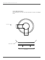
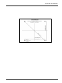
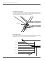
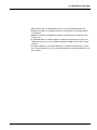
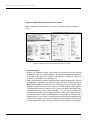
t80W
Installation and Operation User Guide
Marine Satellite Communication Antenna System
Serial number of the product
This serial number will be required for the all troubleshooting or service inquiries.
© 2012 Intellian Technologies Inc. All rights reserved.
Intellian and the Intellian logo are trademarks of Intellian
Technologies, Inc., registered in the U.S. and other countries.
t80W, w-Series, and t-Series are trademarks of Intellian Technologies, Inc.
Intellian may have patents, patent applications, trademarks,
copyrights, or other intellectual property rights covering subject
matter in this document. Except as expressly provided in any
written license agreement from Intellian, the furnishing of this
document does not give you any license to these patents,
trademarks, copyrights, or other intellectual property.
All other logos, trademarks, and registered trademarks are
the property of their respective owners. Information in this
document is subject to change without notice.
Every effort has been made to ensure that the information
in this manual is accurate. Intellian is not responsible
for printing or clerical errors.
Americas
Europe
MEA & APAC
Tel949-727-4498
Toll Free888-201-9223
Fax949-271-4183
[email protected]
Tel+31-1-0820-8655
Fax+31-1-0820-8656
[email protected]
Tel+82-2-511-2244
Fax+82-2-511-2235
[email protected]
Intellian Technologies USA, Inc.
9004 Research Drive
Irvine, CA 92618, USA
Intellian B.V.
Bristolstraat 1, 3047AB
Rotterdam, Netherlands
Intellian Technologies, Inc.
2F Dongik Bldg., 98 Nonhyun-dong,
Gangnam-gu, Seoul 135-010, Korea
Doc. No. 2012U1-UM1031-V1_1
INDEX
t80W – Marine Satellite TV Antenna System
4
INDEX
INTRODUCTION
5
Introduction to Intellian t80W
6
Features of Intellian t80W
7
INSTALLING THE ANTENNA
8
System Package
9
Planning the Installation
13
Antenna Installation
16
INSTALLING THE ACU
26
Mounting the ACU
27
Connecting the System Cables
29
Ship Gyrocompass Connection
31
OPERATING THE ACU
32
Introduction
33
Normal mode
34
Setup mode
38
Installation Settings
39
Antenna Settings
42
Satellite Settings
57
System Settings
66
OPERATION THE PC PROGRAM
72
Introduction
73
Program Initialing and Serial Port Setup
74
Main Menu
75
Controller Menus
78
Set Antenna GPS and Find Antenna Angle
78
Set Satellite Information
79
Set Tracking Information of Satellite [Primary]
80
Set Tracking Information of Satellite [Secondary]
82
Move Antenna and Skew Calibration
83
Antenna Information and Set Antenna Parameters for Control
84
Diagnosis & Set Antenna Parameters for Control
86
WARRANTY
88
Appendix: t80W Technical Specification
89
INTRODUCTION
INTRODUCTION
Introduction to Intellian t80W
Features of Intellian t80W
5
t80W – Marine Satellite TV Antenna System
Introduction to Intellian t80W
The Intellian t80W antenna locks onto satellites quickly and provides seamless
operation in all regions, offering global coverage. The antenna delivers this
performance by utilizing a fully stabilized 3-axis platform, as well as a fourth axis for
LNB auto-skew control. In addition, built-in as standard, the internal GPS combined
with Intellian's patented Wide Range Search (WRS®) provides the fastest satellite
acquisition possible. Multiple HD receivers can be connected to the system as
standard, providing a truly hands off global coverage depending on the regions
visited.
The Intellian t80W incorporates the patented WorldView™ LNB (Low Noise BlockDown Converter), which automatically switches frequency depending on the region
the antenna is operating in; all of the switching information is contained in the
Antenna Control Unit (ACU). As the satellite TV provider is selected electronically,
there is no requirement to purchase multiple LNB modules, reconfigure complex
systems and manually change the LNB unit inside the antenna dome each time the
vessel crosses into a different satellite service region.
The t80W antenna has a broad elevation range, from -15° to +110°, enabling
operation in all conditions and the cross level axis ensures uninterrupted viewing
even when the antenna is operating near the equator. The t80W dome is designed
to complement the v80G VSAT antenna, providing customers with a compact dual
antenna solution for communications and entertainment.
All Intellian antenna systems are designed, manufactured and tested to withstand
the company's industry-leading standards for vibration and extreme shock in all sea
states and weather conditions.
6
INTRODUCTION
Features of Intellian t80W
Global Satellite Services Compatibility
Intellian t80W provides boaters with seamless and uninterrupted satellite TV service
across multiple coverage areas and service providers offering cost-effective solutions
and straightforward, simple operation from the Americas (circular polarized), as well
as Europe, the Middle East and the Asia Pacific region (linear polarized) with one
LNB module.
Hands-Free WorldViewTM LNB Module
The WorldViewTM LNB module is built with precise pioneering technology of ±25
kHz (±2.5ppm) stability and is designed to receive multi-band and multi-polarization
satellite TV services around the globe. Therefore, boaters are no longer required to
manually switch out the LNB inside the antenna dome or re-wire the system when
the vessel travels from region to region.
DVB-S2 Digital TV Receptions
Some of the HD TV services have moved onto DVB-S2 and will be more in the
future. Thanks to Intellian’s groundbreaking DVB-S2 digital TV technology, now
boaters are able to enjoy their favorite DTH entertainment at sea, just like home.
Wide Elevation Range
The wide elevation range from -15° to 110° enables the t80W to have seamless
signal reception while the vessel is traveling near the Equator or Polar Regions.
Global Satellite Library
The t80W includes the pre-programmed global satellite library which allows the
boaters to select the desired satellite while travelling from region to region. Once
the satellite is selected the WorldViewTM LNB module will automatically switch to the
corresponding local frequency to receive the signal.
7
t80W – Marine Satellite TV Antenna System
INSTALLING THE ANTENNA
System Package
Antenna Unit
ACU (Antenna Control Unit)
Installation Kit
Planning the Installation
Selection of Antenna Installation Site
System Cables
Power Requirement
Tools Required for Installation
Antenna Installation
Unpacking the t80W Package Box
Antenna Dimensions
Antenna Mounting Templates
Installing the System Cables
Mounting the Radome
RF Cable Connections
Position the Radome
8
INSTALLING THE ANTENNA
System Package
The Intellian t80W consist of two major units, an antenna unit and an antenna
control unit (ACU).
Antenna Unit
The antenna unit includes an antenna pedestal inside a radome assembly unit. The
pedestal consists of the satellite antenna main dish and sub-reflector module with
a WorldViewTM LNB module mounted on a stabilized pedestal. The radome protects
the antenna pedestal assembly unit from the severe marine environment.
ACU (Antenna Control Unit)
Antenna Control Unit (ACU) provides the power to the antenna and controls the
various settings of the antenna. Additionally, VFD (Vacuum Fluorescent Display)
allows you to operate the ACU in the dark.
Front panel
Rear panel
9
t80W – Marine Satellite TV Antenna System
Installation Kit
Contains the items required for securing the antenna unit and ACU to the vessel.
Antenna
Q’ty
Description
5
Hex. Bolt
5
Flat Washer
Size
Remark
M12 x 60L
M12
Antenna-Deck
5
ACU
Spring Washer
M12
10
Hex. Nut
M12
Q’ty
Description
Size
Remark
5
Self-Tapping
Screw
ø 4 x 16
Table Mount
Bracket
Flat Head Screw
M3 x 8L
Rack Mount
Bracket ACU
Sems Bolt
M3 x 12L
Table Mount
Bracket ACU
10
5
10
INSTALLING THE ANTENNA
Other Components
Image
Q’ty
Description
2
Size
Remark
Rack
-
ACU-19inch Rack
Table
-
ACU-Table
ACU
Bracket
1
2
2
1
RG6 Cable
30m
ANT - ACU RF Cable
3
1
RG6 Cable
3m
ACU - IRD Cable
4
1
AC Power Cable
(CEE 7/7)
1.5m
ACU Power
5
1
PC Serial Cable
1.8m
ACU to PC
6
1
USB Cable
(A-A/M-M)
1.8m
ACU to PC
7
1
Synchro
Connector
AK950-5
ACU (Synchro)
8
1
Step by Step
Connector
AK950-4
ACU (Step-by-Step)
9
1
NMEA Out
Connector
AK950-3
ACU (NMEA Out)
10
2
Gyro NMEA / GPS
NMEA In
Connector
AK950-2
ACU (Gyro NMEA / GPS
NMEA In Connector)
11
2
Rubber Gland
RG6
RG6 Cable-Antenna
11
t80W – Marine Satellite TV Antenna System
12
12
5
Hex Socket
Head Cap
M6x40L
Radome (Top-Bottom)
13
5
Dome Washer
M6
Radome (Top-Bottom)
14
1
Installation CD
-
-
15
1
User Manual
-
-
16
1
Mounting
Template
-
-
INSTALLING THE ANTENNA
Planning the Installation
Selection of Antenna Installation Site
Install the antenna in accordance with the following procedures to insure maximum
performance of the antenna.
The antenna should be installed in a place where there is all round clear view of
the horizon. Please be sure there are no obstacles within 15 degrees above the
antenna. Any obstacles can prevent the antenna from tracking the satellite signal
(Refer to the drawing).
Do not install the antenna near by the radar especially on the same plane as their
energy levels may overload the antenna front-end circuits. It is recommended to
position the antenna at least 4 feet (1.2m) above or below the level of the radar and
minimum of 15 feet (4.6m) away from the high power short wave radars.
The mounting platform should be rigid enough and not subjected to excessive
vibration. The movement of the antenna can be minimized by installing at the center
of the vessel. For optimal performance of the antenna, it is not recommended to
install at any corner of the vessel, where the movement of the vessel is the greatest.
Install the bottom of the antenna parallel to the surface of the sea and fix tightly to
the structure of the vessel.
When setting the antenna down, be careful not to damage the RF connector. Striking
the connectors on the bottom directly will damage the connector.
Elevation Limit
of Obstacles
15°
Antenna Unit
Obstacle
13
t80W – Marine Satellite TV Antenna System
System Cables
Before installing the system cables, you need to take the following points into
consideration.
1. All cables need to be well clamped and protected from physical damage and
exposure to heat and humidity.
2. Cable with a tight bend radius is not allowed.
3. Where a cable passes through an exposed bulkhead or deck head, a watertight
gland or swan neck tube should be used.
RF Cable (Customer Furnished)
Due to the voltage losses across the length of the RF coax on L-Band, Intellian
recommends the following 75 ohm coax cable types for standard system
installations. For cables that run longer than 100 meters, please consult Intellian
Technologies.
Run Length
Coax Type
Up to 35 meters
RG6 or LMR-300-75
Up to 60 meters
RG11 or LMR-400-75
Up to 100 meters
LMR-600-75
Gyro Compass / GPS Interface Cable (Customer Furnished)
Multi-conductor, Shielded
2 conductors for NMEA
Power Requirement
Intellian t80W has been designed to work on a vessel’s power supply rated at 110-220 V AC.
14
INSTALLING THE ANTENNA
Tools required for Installation
Phillips Head
Screwdriver
Flat Head
Screwdriver (Min. 5mm)
5 mm Allen/Hex key
11 mm Spanner
13 mm Spanner
19 mm Spanner
15
t80W – Marine Satellite TV Antenna System
Antenna Installation
Unpacking the t80W Package Box
Step 1.
Remove the top panel.
Step 2.
Remove ACU box and installation kit box.
16
INSTALLING THE ANTENNA
Step 3.
Remove the 4 shipping bolts that mount the antenna to the pallet.
17
t80W – Marine Satellite TV Antenna System
Step 4.
Open the top radome and remove the shipping restraints
(3 fixing brackets mounted to the antenna pedestal and the azimuth axis).
M6 Dome Washer
M6 Hex Wrench Bolt
18
INSTALLING THE ANTENNA
Antenna Dimensions
The method of installation and mounting of antenna may vary with vessel design
but the following procedures are applicable in most situations, and will result in a
secure and effective installation. Confirm the height and diameter of the antenna
before installing it.
114 cm (44.9")
Radome Dimensions
113 cm (44.5")
19
t80W – Marine Satellite TV Antenna System
30.4cm (12”)
Bow direction
24.75 cm (9.74")
Antenna Mounting Templates
The mounting holes must be in the exact same place as shown in the diagram
below.
24.75 cm (9.74")
30.4 cm (12")
Radome Bottom
52 cm (20.5”)
20
24.75cm(9.74")
INSTALLING THE ANTENNA
24.75cm(9.74")
21
t80W – Marine Satellite TV Antenna System
Installing the System Cables
The cables must be routed from the antenna through the deck and through various
space on the ship to the antenna control unit. When pulling the cables in place,
avoid sharp bends, kinking, and the use of excessive force.
Shrinkage Guide
Rubber Gland
Mounting the Radome
Bolt the radome base directly to the support pedestal. Makesure to use the Intellian
supplied blots from the accessory box when you mount the radome.
Antenna Unit
M12 Hex. Bolt
M12 Flat Washer
Deck
M12 Flat Washer
M12 Spring Washer
M12 Hex Nut
19 mm Spanner
22
INSTALLING THE ANTENNA
RF Cable Connections
Before installing the RF cable, ensure that the RF cable labeled with RF1 has to be
connected properly between the antenna control unit and the power switch box.
Connect the four RF cables to the RF connectors using an 11mm spanner. Ensure
that the power switch is off during the installation period. When all the hardware
and cables have been installed, turn on the power switch. Use RG11 rubber gland
if you’re using RG11 cable instead of RG6 cable.
RF 1 Cable
RF 2 Cable
RF 3 Cable
RF 4 Cable
Spare
Power Switch
23
t80W – Marine Satellite TV Antenna System
Reinstall the top radome.
M6 Dome Washer
M6 Hex Wrench Bolt
WARNING: Please ensure that your Intellian system is ALWAYS powered ON upon
leaving the dock. Failure to follow these instructions could result in damaging mechanical
parts in the antenna and/or possibly void your warranty. Intellian strongly recommends
to restrain the antenna pedestal properly while underway when power is removed from
the antenna. The normal operating condition for the t80W is to remain powered up at
all times.
24
INSTALLING THE ANTENNA
Position the Radome
The radome should be positioned with the BOW marker aligned as closely as
possible to the ship’s centerline.
Recommended size of the
support pedestal
Supporting Pole
Appr Ø25.4cm(10”)
Base Panel
Min 120cm(47”)
Base Panel
Min 0.8cm(0.3”)
Max 1.2cm(0.5”)
25
INSTALLING THE ACU
Mounting the ACU
19” Rack Mount Type
Table Mount Type
ACU Dimensions
Selection of ACU Installation Site
Connecting the System Cables
Up to 4 Receivers Connection
Multi-Switch Connection
Ship Gyrocompass Connection
INSTALLING THE ACU
Mounting the ACU
Intellian supplies two types of mounting methods (a) 19” Rack Mount Type and (b)
Table Mount Type to mount your ACU.
Figure 01. 19" Rack Mount Type
(a) 19” Rack Mount Type
- The ACU should be installed using the two supplied Rack Mounting Brackets
which allow ACU to be installed in the 19” rack (Customer Supplied).
- Using the bolts supplied, attach the mounting brackets to the sides of the ACU.
- Place the ACU in the 19" rack.
- Connect the cables to the rear of the ACU.
Figure 02. Table Mount Type
(b) Table Mount Type
- The ACU should be installed using the two supplied Table Mounting Brackets
which allow for a top or bottom mounting configuration.
- Using the bolts supplied, attach the mounting brackets to the sides of the ACU.
- Place the ACU in the location where it is going to be installed.
- Using a pencil to mark the 4 hole positions (2 on each side), and fix the ACU using
the self-tapping screws.
- Connect the cables to the rear of the ACU.
WARNING: Ensure that the cables connected to the ACU are long enough to prevent
damage when the ACU is pulled out from the rack.
27
t80W – Marine Satellite TV Antenna System
ACU Dimensions
Figure 03. Dimension of ACU
Selection of ACU Installation Site
• The ACU should be installed below deck, in a location that is:
• Dry, cool, and ventilated.
• Easy accessible from your main TV viewing area.
28
INSTALLING THE ACU
Connecting the System Cables
For your satellite TV system to work properly, the system will have to be properly
connected with all of the provided components, as shown in the figure below.
Separate purchase of a satellite receiver, multi-switch, and TV is required.
Up to 4 Receivers Connection
In Universal LNB mode, RF1, RF2, RF3 and RF4 can be connected, however,
when you switch and use the system from universal LNB mode (ex. Europe) to
single LNB mode (ex. US), RF3 and RF4 will not work and only RF1 and RF2 will
transfer the satellite's signal.
ACU
FG
-
Receiver 1
ANT RF1
+
+
DC 9 - 30 V
FUSE
RECEIVER
NMEA
PC INTERFACE
Receiver 2
RF1
RF2 (Optional)
Receiver 3
RF3 (Optional)
Receiver 4
RF4 (Optional)
Figure 04. t80W System Diagram
•
•
•
•
•
Connect the RF cable from the ACU's RF1 connector on the power switch box
located inside of the radome to the ANT. RF1 connector on the ACU.
Connect the RF cable from the RECEIVER connector on the ACU to the RF
connector on the IRD.
Connect the ship’s gyro to the Gyrocompass Input on the ACU.
Connect the power cable from the AC power connector on the ACU to a
power source at 110- 220 V AC.
Press the POWER ON switch on the ACU to start the operation of the antenna
system.
29
t80W – Marine Satellite TV Antenna System
Multi-Switch Connection
When you use the multi-switch in single LNB mode, you need to connect RF1 and
RF2 to the low-band (Horizontal Low and Vertical Low) outputs of the 4x8 multiswitch and disable DisEqC function while connecting to a receiver other than a
European receiver. In Universal LNB mode, RF1~ RF4 can be connected to any
4 outputs of 4x8 multi-switch. However when you use the system for single LNB
mode, RF3 and RF4 ports will not transfer the RF signal.
RF1
RF2
13V
18V
13V+22kHz
RF3/RF4
18V+22kHz
Vertical Low
Horizontal Low
Vertical High
Horizontal High
ACU
FG
-
ANT RF1
+
+
DC 9 - 30 V
FUSE
Receiver 1
RECEIVER
NMEA
PC INTERFACE
VH
RF1
RF2
RF3
R2
R3
HH
R4
VL
R5
HL
R6
R7
4x8
Multi switch
RF4
Figure 05. Multi-switch Configuration
30
Receiver 8
INSTALLING THE ACU
Ship Gyrocompass Connection
For satellite tracking, you must connect a ship’s gyrocompass to the antenna
system through the gyro interface on the ACU. If the ship’s gyrocompass output is
other than NMEA 0183 separate purchase of a Gyro to NMEA converter is
required.
•
•
NMEA 0183 Gyrocompass Interface Cable (Customer Furnished)
Type: Multi-conductor ( 2 conductors for NMEA 0183).
Gyrocompass Input
Step by Step
Synchro
GPS
NMEA
NMEA in
NMEA out
Ship’s gyrocompass
Figure 06. Ship's Gyrocompass Connection
NOTE: Determine the type of gyrocompass OUTPUT on the ship, assure that the
GYRO TYPE parameter is set correctly (refer to the operation section of this menu).
The heading in most cases will be 000.0 and you will have to enter the initial value of
the ships current value whenever you turn on the ACU.
The ship’s heading is not required to input when your system is connected to NMEA
0183 Heading Gyrocompass output.
31
OPERATING THE ACU
Introduction
Normal Mode
Startup
Change of Target Satellite
Monitoring Current Status
Setup Mode
Installation Settings
Antenna Settings
Manual Search
Set Antenna LNB pol Angle
Set Antenna Position
Set Search Parameters
Set Antenna Parameters
Set Block Zone
Antenna Diagnostic Test
Satellite Settings
Set Satellite Pair
Edit Satellite Information
Set Region
Find Transponders
System Settings
Set Location
Set Remocon
System Backup & Restore
View Versions
OPERATING THE ACU
Introduction
This section of the handbook describes how to set up your Satellite TV System after
installation using the ACU.
Mode
Arrow Keys
ACU Soft Keys
PC
Soft Key Functions
USB
Memory
Status
LED
Return
Function
Number
Keys
Power
Switch
Soft key
Function
MODE
Enter SETUP mode
RETURN
In SETUP mode: return to previous menu / option or save the
adjusted settings.
In normal mode: return to the first page of antenna current status.
FUNCTION
Save the adjusted settings.
ARROW KEYS
Select from the alternative options to increse or decrese the
selected character to the desired value.
OK
Enter next step / menu
NUMBER KEYS
Input the numbers
Figure 07. Soft Key Functions
WARNING: Please ensure that your Intellian system is ALWAYS powered ON upon
leaving the dock. Failure to follow these instructions could result in damaging mechanical
parts in the antenna and/or possibly void your warranty. Intellian strongly recommends
to restrain the antenna pedestal properly while underway when power is removed from
the antenna. The normal operating condition for the t80W is to remain powered up at
all times.
33
t80W – Marine Satellite TV Antenna System
Normal Mode
Startup
With the system installed and power applied, the ACU screen will show the following
sequence.
INTELLIAN TECHNOLOGIES INC.
1. The data communication is being established between the antenna and the ACU.
INITIALIZE - ANTENNA INFO
INTELLIAN W80
2. The ACU receives antenna information.
INITIALIZE - EL POSITION
INTELLIAN W80
3. The elevation angle and cross level angle are initialized.
INITIALIZE - AZIMUTH POSITION
INTELLIAN W80
4. The azimuth angle is initialized.
INITIALIZE - FIND NOISE LEVEL
INTELLIAN W80
5. The antenna measures the noise levels of the default satellites.
INITIALIZE - SAT POSITION
INTELLIAN W80
6. The antenna returns to the target satellite position.
SEARCH3 ASTRA_1
AGC:301
[VL]
AZ:292.7( 202.7) EL: 48.3 SK: -72.0
7. The antenna is searching for the target satellite.
TRACKING ASTRA_1
AGC:501
[VL]
AZ:292.7( 202.7) EL: 48.3 SK: -72.0 Fn
8. The antenna has locked onto the satellite.
34
OPERATING THE ACU
Change of Target Satellite
Your antenna is programmed with three or two candidates of target satellites as
default.While the antenna is in tracking mode, press the Left arrow key to display
the current satellite. To change the target satellite, press the number key assigned
to the target satellite. The target satellite is changed and automatically tracked by
the antenna.
TRACKING [ ] ASTRA_1
[2] HOT_SPOT
[3] ASTRA_3
fn
[3] ASTRA_3
fn
[3] HOT_SPOT
fn
1. The antenna is tracking satellite [1].
TRACKING [ ] HOT_SPOT
[1] ASTRA_1
2. Press the NUMBER key 2 for tracking satellite [2].
TRACKING [ ] ASTRA_3
[2] ASTRA_1
3. Press the NUMBER key 3 for tracking satellite [3].
35
t80W – Marine Satellite TV Antenna System
Monitoring Current Status
While POWER ON to Intellian t80W, ACU displays the status of the antenna. The
various ACU displays may be shown according to the current status of the antenna.
TRACKING ASTRA_1
AGC:501
[VL]
AZ:292.7( 202.7) EL:48.3 SK: -72.0
Fn
1. True azimuth [ 292.7] position of the antenna is the sum of ships heading 090.0
[ HDG ] and antenna relative [ 202.7]. Current IF signal (AGC) is displayed. will
only be displayed when the signal is strong enough to lock. [ VH ] indicates vertical
high band. VL: Vertical Low, HL: Horizontal Low, HH: Horizontal high. Press the
UP and DOWN arrow keys to increase and decrease the LNB skew angle.
[SAT] F:11856 S:27500 DVB_D L:9750
[SHIP] 087.37W 41.50N
HDG:090.0
2. Press the RIGHT arrow key to display current satellite, GPS [SHIP] and ship's heading [
HDG ].
Satellite Information :
Frequency : 11856 MHz
Symbol rate : 27500 KHz
Verification method : DVB_Decode
LNB local frequency : 9750 MHz
GPS Information :
Longitude : West/East
Latitude : North/South
will be displayed flashing only if ACU receives the correct GPS input
Heading Information:
will be displayed flashing only if ACU receives the correct NMEA heading input
[PWR] ANT: 23.9V
LNB: 13V + 0KHz
ACU: 27.0V
IRD: 13V + 0KHz
3. Press the RIGHT arrow key to display ACU and antenna, LNB and IRD voltage
information).
36
OPERATING THE ACU
Antenna and ACU Voltage :
Due to the voltage losses across the RF1 coaxial cable, ensure that the output voltage of
the ACU is within 27± 1 V DC and the minimum antenna operation voltage is above 16V
DC.
LNB and IRD Voltage :
Voltage
13V
DiSEqC
18V
•
0KHz
Discription
22KHz
•
•
Vertical Low (VL)
•
Horizontal Low (HL)
•
•
•
Vertical High (VH)
•
Horizontal High (HH)
WR-917W
ANT. Serial
1.00
VP-T701
ACU Serial
1.00(1.00)
4. Press the RIGHT arrow key to display the antenna, ACU and Library version.
Keep pressing the Right arrow key to return to the previous view.
TRACKING [ ] ASTRA_1
[2] HOT_SPOT
[3] ASTRA_3
fn
5. Press the RIGHT arrow key to display the current tracking satellite.
ANTENNA IS UNWRAPPING
6. The antenna is winding/ unwinding the cables in the antenna. The necessity of “unwrap”
is based on how far the ship has turned in one direction on the other.
SAVE CURRENT SAT INFO ?
YES
NO
7. While the antenna is in tracking mode, Press the FUNCTION key to save the bow offset
or abort and return to the previous view.
37
t80W – Marine Satellite TV Antenna System
Setup Mode
Enter the SETUP mode simply follow the instructions below.
TRACKING ASTRA_1
AGC:501
[VL]
AZ:292.7( 202.7) EL:48.3 SK: -72.0
Fn
1. While the antenna is in tracking mode, press the MODE key for setup mode.
SETUP MODE ?
YES
NO
2. Press the LEFT arrow key to move cursor to YES and press the OK key to enter
setup mode or press the RIGHT arrow key to move cursor to NO and press the OK key
to abort and return to the previous view.
38
OPERATING THE ACU
Installation Settings
SETUP MODE ?
YES
NO
1. Press the LEFT arrow key to move cursor to YES and press the OK key to enter SETUP
mode.
+ANTENNA
+SATELLITE
+SYSTEM
+INSTALLATION
2. Press the arrow keys to move cursor to INSTALLATION menu and press the OK key to
enter it.
SELECT CONTINENT
SELECT REGION
EUROPE
DENMARK
3. Set CONTINENT. Press the UP and DOWN arrow keys to select the continent
that you are in. Press the OK key to set the settings.
SELECT CONTINENT
SELECT REGION
EUROPE
DENMARK
4. Set REGION. Press the UP and DOWN arrow keys to select the region that
you are in. Press the OK key to set the settings.
LATITUDE
LONGITUDE
HEADING
41.50N
087.37W
000.0
5. Set the current LATITUDE.
Press the LEFT and RIGHT arrow keys until the desired character is underscored
(selected). Press the UP and DOWN arrow keys to increase or decrease the value.
Or press the NUMBER keys to set the desired value directly.
Press the OK key to set the LATITUDE.
LATITUDE
LONGITUDE
HEADING
41.50N
087.37W
000.0
6. Set the current LONGITUDE.
Press the LEFT and RIGHT arrow keys until the desired character is underscored
(selected). Press the UP and DOWN arrow keys to increase or decrease the value.
Or press the NUMBER keys to set the desired value directly.
Press the OK key to set the LONGITUDE.
39
t80W – Marine Satellite TV Antenna System
LATITUDE
41.50N
LONGITUDE
HEADING
087.37W
000.0
7. Set the ship's current HEADING.
Entry of ships heading is not required when your system is connected to a NMEA0813
Heading Gyrocompass output.
Press the LEFT and RIGHT arrow keys until the desired character is underscored
(selected). Press the UP and DOWN arrow keys to increase or decrease the value.
Or press the NUMBER keys to set the desired value directly.
Press the OK key to set the HEADING.
GYRO TYPE
NMEA
BOW ADJUST
000
8. Set the GYRO TYPE.
Determine the type of gyrocompass that is used on the ship. Ensure that the Gyro
Type is set correctly. Press the UP and DOWN arrow keys to select the gyro type
and press the OK key to set the GYRO TYPE.
GYRO TYPE
NMEA
BOW ADJUST
000
9. Set the BOW ADJUST.
The radome should be positioned with the BOW marker aligned as close as possible
to the centerline of the ship. Small variations from actual alignment can be
compensated with the BOW ADJUST, so precise alignment is not required.
Press the LEFT and RIGHT arrow keys until the desired character is underscored
(selected). Press the UP and DOWN arrow keys to increase or decrease the value.
Or press the NUMBER keys to set the desired value directly.
Press the OK key to set the BOW ADJUST.
BACKUP SETTING
YES
10. Set the BACKUP SETTINGS.
BACKUP SETTINGS is to determine whether to back up the installation setting or
not. Press the UP and DOWN arrow keys to select "YES" to backup or "NO" to NOT
backup and press the OK key to set the BACKUP SETTINGS.
40
OPERATING THE ACU
LOAD ?
YES
NO
11. Press the RETURN key to load the current setting or abort and return to the
previous view.
LOADING ...
DO NOT TURN OFF !
12. Setting is being loaded to the system.
The ACU will restart the system automatically after uploading the setting.
DO NOT turn off ACU power when uploads are being processed.
SEARCH [ ] THOR_1
[2] SIRIUS_1
13. Regional satellite library has been updated.
41
t80W – Marine Satellite TV Antenna System
Antenna Settings
Manual Search
Search the desired satellite manually.
SETUP MODE ?
YES
NO
1. Press the LEFT arrow key to move cursor to YES and press the OK key to enter SETUP
mode.
+ANTENNA
+SATELLITE
+SYSTEM
+INSTALLATION
2. Press the OK key to enter ANTENNA menu.
+MANUAL SEARCH
+SET POL ANGLE
+GO POSITION
+SEARCH PARAM
3. Press the OK key to enter MANUAL SEARCH menu.
STEP SIZE
AZIMUTH
231.7
# 00.2 #
ELEVATION
48.3
AGC
501
4. Current IF signal level (AGC) is displayed to assist you in manually peaking EL
for best signal level. Press the NUMBER key to change the step size(Range :
0.1~9.9). Press the LEFT and RIGHT arrow keys to move azimuth by step size
(Range : 0~360). Press the UP and DOWN arrow keys to move elevation by step
size(Range : 0~90). Press the FUNCTION key to save the bow offset when the antenna
locks onto the peak level of the AGC signal.
SAVE CURRENT SAT INFO?
YES
NO
5. If the current settings are able to lock onto the satellite, press the LEFT key to
move cursor to YES and press the OK key to save the bow offset. It will shorten the
satellite acquisition time next time. Or you can press the RIGHT key to move
cursor to NO and press the OK key to abort and return to the previous view.
42
Fn
OPERATING THE ACU
Setup Antenna LNB pol Angle
SETUP MODE ?
YES
NO
1. Press the LEFT arrow key to move cursor to YES and press the OK key to enter SETUP
mode.
+ANTENNA
+SATELLITE
+SYSTEM
+INSTALLATION
2. Press the OK key to enter ANTENNA menu.
+MANUAL SEARCH
+SET POL ANGLE
+GO POSITION
+SEARCH PARAM
3. Press the RIGHT arrow key to move cursor to SET POL ANGLE menu and press the OK
key to enter it.
P O L T YP E
LINEAR
P O L A DJ U ST
CALIBRATION
4. Press the UP and DOWN arrow keys to select the POL TYPE (Linear / Circular
polarization) of the LNB.
P O L T YP E
LINEAR
P O L A DJ U ST
CALIBRATION
5. Press the UP and DOWN arrow keys to select the POL ADJUST (Calibration/ Manual
Adjust). When you replace the control board or LNB skew sensor, select CALIBRATION
to calibrate LNB pol. angle.
L N B PO L A N G L E
S I G N A L : 18 0
20
6. This menu will only be displayed when “ Manual Adjust” on previous step is selected.
Press the UP and DOWN arrow keys to increase or decrease the LNB pol angle
manually and the correspondent SIGNAL level will be displayed next to it.
Press the RETURN key to return to the previous view.
43
t80W – Marine Satellite TV Antenna System
Antenna Go Position
SETUP MODE ?
YES
NO
1. Press the LEFT arrow key to move cursor to YES and press the OK key to enter SETUP
mode.
+ANTENNA
+SATELLITE
+SYSTEM
+INSTALLATION
2. Press the OK key to enter ANTENNA menu.
+MANUAL SEARCH
+SET POL ANGLE
+GO POSITION
+SEARCH PARAM
3. Press the RIGHT arrow key to move cursor to GO POSITION menu and press the
OK key to enter it.
A Z I M U TH
+ 2 8 8 .7
ELE VATION
+41.0
A Z :2 8 8. 7
EL:41.0
4. Set the AZIMUTH position.
Press the LEFT and RIGHT arrow keys until the desired character is underscored
(selected). Press the UP and DOWN arrow keys to increase and decrease the selected
character. Or press the NUMBER keys to set the desired value directly.
Press the OK key to set the AZIMUTH position.
A Z I M U TH
+ 2 8 8 .7
ELE VATION
+41.0
A Z :2 8 8. 7
EL:41.0
5. Set the ELEVATION position.
Press the LEFT and RIGHT arrow keys until the desired character is underscored (selected).
Press the UP and DOWN arrow keys to increase and decrease the selected character. Or
press the NUMBER keys to set the desired value directly.
Press the OK key to set the ELEVATION position and execute both the new azimuth
and elevation position.
A Z I M U TH
+ 2 8 8 .7
ELE VATION
+41.0
6. ACU displays current antenna position.
Press the RETURN key to return to the previous view.
44
A Z :2 8 8. 7
EL:41.0
OPERATING THE ACU
Search Parameters
SETUP MODE ?
YES
NO
1. Press the LEFT arrow key to move cursor to YES and press the OK key to enter SETUP
mode.
+ANTENNA
+SATELLITE
+SYSTEM
+INSTALLATION
2. Press the OK key to enter ANTENNA menu.
+MANUAL SEARCH
+ SET POL ANGLE
+GO POSITION
+SEARCH PARAM
3. Press the DOWN arrow keys to move cursor to SEARH PARAM and press the OK key to
enter it.
SEARCH WAIT TIME
030
INCREMENT STEP
0.50
4. Set the SEARCH WAIT TIME. (Range : 20 - 120 sec)
Set the time-out for automatic initiation of a search after the signal level drops below threshold.
Press the LEFT and RIGHT arrow keys until the desired character is underscored (selected).
Press the UP and DOWN arrow keys to increase and decrease the selected character Or
press the NUMBER keys to set the desired value directly.
Press the OK key to set the SEARCH WAIT TIME.
Press the RETURN key to save or abort and return to the previous view.
SEARCH WAIT TIME
030
INCREMENT STEP
0.50
5 Set the INCREMENT STEP size.
Press the LEFT and RIGHT arrow keys until the desired character is underscored (selected).
Press the UP and DOWN arrow keys to increase and decrease the selected character. Or
press the NUMBER keys to set the desired value directly.
Press the OK keys to set the INCREMENT STEP.
Press the RETURN key to save or abort and return to the previous view.
45
t80W – Marine Satellite TV Antenna System
+SEARCH 1
+SEARCH 2
+SEARCH 3
6. SEARCH 1 menu is reserved for future use.
Use SEARCH 2 and SEARCH 3 menus to set the size of search pattern range.
Move cursor to SEARCH 2 or SEARCH 3 and press the OK key to enter SEARCH 2 or
SEARCH 3 menu.
SEARCH 2 : a search pattern 2 will automatically be initiated when AGC falls below the current detect level threshold setting.
SEARCH 3 : a search pattern 3 will automatically be initiated when AGC falls below the current tracking level threshold setting.
Peak Level
Tracking Level
Detect Level
Noise Level
A search pattern will automatically be initiated when AGC falls below the current threshold
setting (indicates that satellite signal has been lost). Search is conducted in a two-axis
pattern consisting of alternate movements in azimuth (AZ) and elevation. These parameters
should only be changed by an authorized service technician. Improper setting of these
parameters will cause your system to perform improperly.
46
OPERATING THE ACU
S2
AZ. RANGE
16
EL. RANGE
12
7. Set the AZIMUTH RANGE. (Range : 0 - 540)
Press the LEFT and RIGHT arrow keys until the desired character is underscored (selected).
Press the UP and DOWN arrow keys to increase and decrease the selected character. Or
press the NUMBER keys to set the desired value directly.
Press the OK key to set the new AZ RANGE.
S2
AZ. RANGE
EL. RANGE
12
16
8. Set the ELEVATION RANGE. (Range : 0 - 90)
Press the LEFT and RIGHT arrow keys until the desired character is underscored (selected).
Press the UP and DOWN arrow keys to increase and decrease the selected character. Or
press the NUMBER keys to set the desired value directly.
Press the OK key to set the new EL RANGE.
+SEARCH 1
+SEARCH 2
+SEARCH 3
9. Press the RETURN key to save or abort and return to the previous view.
SAVE ?
YES
NO
10. Press the LEFT arrow key to move cursor to YES and press the OK key to save and execute the current settings. Or press the RIGHT arrow key to move cursor to NO and press
the OK key to abort and return to the previous view.
47
t80W – Marine Satellite TV Antenna System
Antenna Parameters
These parameters should only be changed by an authorized service technician.
Improper setting of these parameters will cause your system to perform improperly.
SETUP MODE ?
YES
NO
1. Press the LEFT arrow key to move cursor to YES and press the OK key to enter SETUP
mode.
+ANTENNA
+SATELLITE
+SYSTEM
+INSTALLATION
2. Press the OK key to enter ANTENNA menu.
+SET PARAMETERS
+ BLOCK ZONE
+DIAGNOSIS
3. Press the arrow keys to move cursor to SET PARAMETERS menu and press the OK key
to enter it.
ENTER PASSWORD
- - - 4. Access to the password protected system. Setup parameters are only required
after installation for repairs of your antenna system. These parameters should only
be changed by an authorized service technician. Improper setting of these
pararmeters will cause your system to perform improperly.
Press 4 digit (1590) password to enter SET PARAMETERS menu.
SCAN OFFSET
55
DISEQC THRES
0100
5. Set the SCAN OFFSET. (Range : 0 -90)
THe scan offset is to offset the angle difference between the black marker on the
sub-reflector and the optical sensor.Press the LEFT and RIGHT arrow keys until the desired
character is underscored (selected). Press the UP and DOWN arrow keys to increase and
decrease theselected character. Or press the NUMBER keys to set the desired value directly.
Press the OK key to set the new SCAN OFFSET.
48
OPERATING THE ACU
SCAN OFFSET
DISEQC THRES
0100
55
6. Set the DISEQC THRES. (Range : 0 - 1000)
The DiSEqC thres is to set the DiSEqC signal threshold level.
Press the LEFT and RIGHT arrow keys until the desired character to be edited is underscored (selected) and press the UP and DOWN arrow keys to increase and decrease the
selected character. Or press the NUMBER keys to set the desired value directly.
Press the OK key to set the new DISEQC THRES.
DETECT LEVEL
060
TRACKING LEVEL
030
7. Set the DETECT LEVEL. (Range : 1-200)
The detect level is to set the satellite signal detection level.
Press the LEFT and RIGHT arrow keys until the desired character is underscored
(selected). Press the UP and DOWN arrow keys to increase and decrease the
selected character. Or press the NUMBER keys to set the new DETEC LEVEL.
Or press the RETURN key to return to the previous view.
DETECT LEVEL
060
TRACKING LEVEL
030
8. Set the TRACKING LEVEL. (Range : 1-200)
The tracking level is to set the satellite signal tracking level.
Press the LEFT and RIGHT arrow keys until the desired character is underscored
(selected). Press the UP and DOWN arrow keys to increase and decrease the
selected character. Or press the NUMBER keys to set the desired value directly.
Press the OK key to set the new TRACKING LEVEL.
Peak Level
Tracking Level
Detect Level
Noise Level
49
t80W – Marine Satellite TV Antenna System
BOW ADJUST
000
EL.ADJUST
00.0
9. Set the BOW ADJUST. (Range : 0 -360 )
The bow adjust is to offset the angle difference between the antenna's bow and the ship's
bow. Press the LEFT and RIGHT arrow keys until the desired character is underscored
(selected). Press the UP and DOWN arrow keys to increase and decrease the selected
character. Or press the NUMBER keys to set the desired value directly.
Press the OK key to set the new BOW ADJUST.
BOW ADJUST
000
EL.ADJUST
00.0
10. Set the EL ADJUST. (Range : ±5 )
The elevation adjust is to offset the angle difference between the mechanical
elevation angle and actual elevation angle.
Press the LEFT and RIGHT arrow keys until the desired character is underscored
(selected). Press the UP and DOWN arrow keys to increase and decrease the
selected character. Or press the NUMBER keys to set the desired value directly.
Press the OK key to set the new EL ADJUST.
WRS DETECT LEVEL
0300
VOLT THRES.
0650
11. Set the WRS DETECT LEVEL (Range : 10 - 5,000)
The WRS level is to set the WRS detection level.
Press the LEFT and RIGHT arrow keys until the desired character is underscored
(selected). Press the UP and DOWN arrow keys to increase and decrease the
selected character. Or press the NUMBER keys to set the desired value directly.
Press the OK key to set the new WRS DETECT LEVEL.
WRS DETECT LEVEL
0300
VOLT THRES.
0650
12. Set the VOLT THRES.
The voltage threshold is to distinguish the voltage between 13V and 18V.
Press the LEFT and RIGHT arrow keys until the desired character is underscored
(selected). Press the UP and DOWN arrow keys to increase and decrease the
selected character. Or press the NUMBER keys to set the desired value directly.
Press the OK key to set the new VOLT THRES.
50
OPERATING THE ACU
OFFSET DIFF.
USE WRS
-040
YES
13. Set the OFFSET DIFF. (Range : ±100 )
The offset difference is to offset the signal difference between RHCP and LHCP.
Press the LEFT and RIGHT arrow keys until the desired character is underscored
(selected). Press the UP and DOWN arrow keys to increase and decrease the
selected character. Or press the NUMBER keys to set the desired value directly.
Press the OK key to set the new OFFSET DIFF.
OFFSET DIFF.
USE WRS
YES
-040
14. Set the USE WRS.
USE WRS is to determine whether the system uses WRS LEVEL or not.
USE WRS and WRS LEVEL are pair functions.
Press the UP and DOWN arrow keys to select "YES" to USE WRS or "NO" to NOT
USE WRS and press the OK key to set the USE WRS.
USE OFFSET
YES
BOW AUTO SAVE
NO
15. Set the USE OFFSET.
USE OFFSET is to determine whether the system uses OFFSET DIFF or not.
USE OFFSET and OFFSET DIFF are pair functions.
Press the UP and DOWN arrow keys to select "YES" to USE OFFSET or "NO" to
NOT USE OFFSET and press the OK key to set the USE OFFSET.
USE OFFSET
YES
BOW AUTO SAVE
YES
16. Set the BOW AUTO SAVE
BOW AUTO SAVE is to determine whether the system saves the bow offset automatically or
not. Press the LEFT and RIGHT arrow keys to select "YES" to SAVE or "NO" to NOT SAVE
the bow info. And press the OK key to set the BOW AUTO SAVE. ("YES" is recommended).
51
t80W – Marine Satellite TV Antenna System
+TILT BIAS
17. Set TILT BIAS
TILT BIAS is to adjust the two solid-state tilt sensors used to provide absolute
cross-level tilt of the antenna and elevation feedback to eliminate long-term pointing
drift (error) between the antenna’s actual position vs. its targeted (or intended) position .
The TILT BIAS is required to set when the system is newly installed or
antenna control board is replaced. Check and see if the bubble is located at the
center of the level vial. If not, press the OK key to enter TILT BIAS menu to adjust.
STEP SIZE
# 0.2
#
ELEVATION
CROSS LEVEL
-00.0
-01.0
18. Press the NUMBER keys to set the step size.
Press the OK keys to select the parameter you wish to edit.
Press the LEFT and RIGHT arrow keys to move CROSS LEVEL OFFSET by step
size. Press the UP and DOWN arrow keys to move ELEVATION OFFSET by step
size.
SAVE ?
YES
NO
19. Press the LEFT arrow key to move cursor to YES and press the OK key to save and
execute the current settings. Or press the RIGHT arrow key to move cursor to NO and
press the OK key to abort and return to the previous view.
52
OPERATING THE ACU
Setup Block Zone
Up to 5 block or radiation hazard zones can be programmed with relative azimuth
and elevation sectors.
SETUP MODE ?
YES
NO
1. Press the LEFT arrow key to move cursor to YES and press the OK key to enter SETUP
mode.
+ANTENNA
+SATELLITE
+SYSTEM
+INSTALLATION
2. Press the OK key to enter ANTENNA menu.
+SET PARAMETERS
+BLOCK ZONE
+DIAGNOSIS
3. Press the RIGHT arrow key to move cursor to BLOCK ZONE menu and press the OK key
to enter it. Up to 5 block zones are allowed to be programmed.
ZONE 1 BLOCK
ON
AZ.1 START
0000
AZ.1 END
0000
EL.1 LIMIT
090
4. Set BLOCK ZONE 1.
Press the UP and DOWN arrow keys to select “ON” to setup the block zone for ZONE 1.
Press the OK key to use BLOCK ZONE 1 and set zone 1 block range.
Press the RETURN key to select the parameter you wish to edit and press the
RETURN key again to save or abort and return to the previous view.
Set the AZ.1 START, AZ. 1 END and EL.1 LIMIT while BLOCK ZONE 1 is ON.
This is the clockwise of the two points. AZ.1 START is where the relative
azimuth starts and AZ.1 END is where the relative azimuth ends (Range: 0- 360°).
EL.1 Limit is where the elevation starts (Range 0- 90°).
Press the LEFT and RIGHT arrow keys until the desired character is underscored
(selected). Press the UP and DOWN arrow keys to increase and decrease the selected
character. Or Press the NUMBER keys to set the desired value directly. Press the OK
key to set the parameter. Press the RETURN key to select the parameter you wish to
edit and press the RETURN key again to save or abort and return to the previous veiw.
53
t80W – Marine Satellite TV Antenna System
ZONE 2 BLOCK
OFF
5. ZONE 2 to ZONE 5 BLOCK setting is same as ZONE 1 BLOCK.
Press the OK key to set ZONE 2 BLOCK and set next parameter.
SAVE ?
YES
NO
6. Press the LEFT arrow key to move cursor to YES and press the OK key to save and
execute the current settings. Or press the RIGHT arrow key to move cursor to NO and
press the OK key to abort and return to the previous view.
54
OPERATING THE ACU
Diagnosis
SETUP MODE ?
YES
NO
1. Press the LEFT arrow key to move cursor to YES and press the OK key to enter SETUP
mode.
+ANTENNA
+SATELLITE
+SYSTEM
+INSTALLATION
2. Press the OK key to enter ANTENNA menu.
+SET PARAMETERS
+BLOCK ZONE
+DIAGNOSIS
3. Press the arrow keys to move cursor to DIAGNOSIS menu and press the OK key to enter it.
DIAGNOSIS
COMMUNICATION
CODE 101
READY
4. Press the UP and DOWN arrow keys to select a full diagnostic test or single
diagnostic test and press the OK key to execute the selected diagnostic test.
DIAGNOSIS
FULL TEST
FULL TEST
5. A full diagnostic test is successfully completed.
DIAGNOSIS
COMMUNICATION
CODE 101
RESULT : PASSED
6. A single diagnostic test is successfully completed.
55
t80W – Marine Satellite TV Antenna System
Diagnosis Code:
CODE 101: The data communication between the antenna and the ACU is tested.
CODE 102: The azimuth motor is tested.
CODE 103: The elevation motor is tested.
CODE 104: The cross-level motor is tested.
CODE 105: The azimuth encoder is tested.
CODE 106: The cross-level encoder is tested.
CODE 107: The rate sensor is tested.
CODE 108: The tilt sensor is tested.
CODE 109: The sensor box motor is tested.
CODE 110: The LNB is tested.
CODE 111: The LNB pol motor is tested.
CODE 112: The sub-reflector is tested.
CODE 113: The antenna power is tested.
CODE 114: The ACU power is tested.
CODE 115: The receiver power is tested.
An example of test result: ••2•••••••••••
•: test is passed
2: test is failed
?: test is in process
Refer 2 to the diagnosis code 102 as shown above for occurred error explanation.
56
OPERATING THE ACU
Satellite Settings
Set Sat. Pair
SETUP MODE ?
YES
NO
1. Press the LEFT arrow key to move cursor to YES and press the OK key to enter SETUP
mode.
+ANTENNA
+SATELLITE
+SYSTEM
+INSTALLATION
2. Press the RIGHT arrow key to move cursor to SATELLITE and press the OK key to enter it.
+SET SAT.PAIR
+ E D I T S A T E L LI T E
+SET REGION
+ F I N D T R A N SP O N D E R
3. Press the OK key to enter SET SAT. PAIR menu.
SET TRIPLE SAT ?
YES
NO
4. Move cursor to YES and press the OK key to enter Tri-Sat mode or move cursor
to NO and press the OK key to enter Dual-Sat mode.
RESET SLOT
D E S T . S A T E L L IT E
PRESET 1
ASTRA_1
5. Press the UP and DOWN arrow keys to select PRESENT SLOT 1, 2 and 3 in TriSat mode or 1 and 2 in Dual-Sat mode.
RESET SLOT
D E S T . S A T E L L IT E
ASTRA_1
PRESET 1
6. Press the UP and DOWN arrow keys to select the DESTINED SATELLITE from the library
(pre-programmed satellites). Press the OK key to set the DESTINED SATELLITE.
SAVE ?
YES
NO
7. Press the LEFT arrow key to move cursor to YES and press the OK key to save and
execute the current settings. Or press the RIGHT arrow key to move cursor to NO and
press the OK key to abort and return to the previous view.
57
t80W – Marine Satellite TV Antenna System
Edit Satellite Information
You are allowed to modify the existing satellite information and input new satellite
information into the ACU as well. It is not recommended for a novice satellite service
user to use this mode.
SETUP MODE ?
YES
NO
1. Press the LEFT arrow key to move cursor to YES and press the OK key to enter SETUP
mode.
+ANTENNA
+SATELLITE
+SYSTEM
+INSTALLATION
2. Press the RIGHT arrow key to move cursor to SATELLITE and press the OK key to enter it.
+SET SAT.PAIR
+ E D I T S A T E L LI T E
+SET REGION
+ F I N D T R A N SP O N D E R
3. Press the RIGHT arrow key and the OK key to enter EDIT SAT. menu.
SELECT SATELLITE TO EDIT
ASTRA_1
4. Press the UP and DOWN arrow keys to select the satellite that you wish to edit and press
the OK key to edit the selected satellite.
EDIT NAME
ASTRA_1
LONGITUDE
019.20E
5. Edit satellite NAME.
EDIT NAME
ASTRA_1
LONGITUDE
019.20E
6. Edit satellite orbit position, LONGITUDE.
VERIFY TYPE
DVB DECODE
VOLTAGE
AUTO
7. Set the satellite VERIFY TYPE*.
Press the UP and DOWN arrow keys to select the verification method for satellite tracking
and press the OK key to set the VERIFY TYPE.
58
OPERATING THE ACU
VERIFY TYPE*
• AGC – use signal level for satellite tracking.
• DVB Lock – use frequency and symbol rate for satellite tracking.
• DVB Decode – use frequency, symbol rate, and NID for satellite tracking.
• DSS Decode – use for DirecTV satellite tracking
VERIFY TYPE
DVB DECODE
VOLTAGE
AUTO
8. Set the LNB VOLTAGE*.
Press the UP and DOWN arrow keys to select the LNB voltage supply method
and press the OK key to set the VOLTAGE ("AUTO" is recommended).
VOLTAGE*
• AUTO: supply both 13V and 18V
• 13V: supply 13V only
• 18V: supply 18V only
DISEQC
POL.TYPE
AUTO
LINEAR
9. Set the DiSEqC Method*
Press the UP and DOWN arrow keys to select DiSEqC Method* and press the OK
key to set the DISEQC ("AUTO" is recommended).
DiSEqC Method*
• AUTO: supply both 0kHz and 22kHz tone
• OFF: supply 0kHz tone only
• ON: supply 22kHz tone only
DISEQC
POL.TYPE
AUTO
LINEAR
10. Set the POL. TYPE* for satellite polarization.
Press the UP and DOWN arrow keys to select POL. TYPE and press the OK
key to set the POL. TYPE.
59
t80W – Marine Satellite TV Antenna System
POL.TYPE*
• LINEAR: Linear polarized satellite
• CIRCULAR: Circular polarized satellite
LOCAL FREQ.
+ T R A C K P A R A M ET E R
10600
11. Set the LNB LOCAL FREQ.* for satellite tracking.
Press the UP and DOWN arrow keys to select LOCAL FREQ and press the OK
key to set the LOCAL FREQ.
LOCAL FREQ*
10500 MHz
10600 MHz
10678 MHz
10700 MHz
10750 MHz
10800 MHz
11000 MHz
11050 MHz
11200 MHz
11250 MHz
11300 MHz
Note: Select 10600MHz for Universal LNB use.
LOCAL FREQ.
+ T R A C K P A R A M ET E R
10600
12. Setup the satellite tracking parameters. Press the OK key to enter the setup menu.
+VER/RHCP LOW
+ H O R / L H C P L OW
+VER/RHCP HIGH
+HOR/LHCP HIGH
13. Press the arrow keys to select the frequency band you wish you edit.
Press the OK key to edit the selected frequency or press the RETURN key to save
or abort and return to the previous view.
60
OPERATING THE ACU
VL
FREQUENCY
11038MHZ
SYMBOL
22000KHZ
NID
0X0001
14. Set the satellite FREQUENCY for VL(vertical Low) / RHCP frequency
Press the LEFT and RIGHT arrow keys until the desired character is underscored (selected).
Press the UP and DOWN arrow keys to increase or decrease the value.
Or press the NUMBER keys to set the desired value directly.
Press the OK key to set the FREQUENCY.
VL
FREQUENCY
11038MHZ
SYMBOL
22000KHZ
NID
0X0001
15. Set the frequency SYMBOL rate (Maximum: 45,000).
Press the LEFT and RIGHT arrow keys until the desired character is underscored (selected).
Press the UP and DOWN arrow keys to increase or decrease the value.
Or press the NUMBER keys to set the desired value directly.
Press the OK key to set the SYMBOL.
VL
FREQUENCY
11038MHZ
SYMBOL
22000KHZ
NID
0X0001
16. Set the frequency NID (Network ID). Range is 0x0000-0xFFFF.
Press the LEFT and RIGHT arrow keys until the desired character is underscored (selected).
Press the UP and DOWN arrow keys to increase or decrease the value.
Or press the NUMBER keys to set the desired value directly.
Press the OK key to set the NID.
61
t80W – Marine Satellite TV Antenna System
Set Region
SETUP MODE ?
YES
NO
1. Press the LEFT arrow key to move cursor to YES and press the OK key to enter SETUP
mode.
+ANTENNA
+SATELLITE
+SYSTEM
+INSTALLATION
2. Press the RIGHT arrow key to move cursor to SATELLITE and press the OK key to enter it.
+SET SAT.PAIR
+ E D I T S A T E L LI T E
+SET REGION
+ F I N D T R A N SP O N D E R
3. Press the arrow key and the OK key to enter SET REGION menu.
SELECT CONTINENT
SELECT REGION
EUROPE
DENMARK
4. Set CONTINENT. Press the UP and DOWN arrow keys to select the continent
that you are in. Press the OK key to set the settings.
SELECT CONTINENT
SELECT REGION
DENMARK
EUROPE
5. Set REGION. Press the UP and DOWN arrow keys to select the region that
you are in. Press the OK key to set the settings.
LOAD ?
YES
NO
6. Press the RETURN key to load the current setting or abort and return to the
previous view.
LOADING ...
DO NOT TURN OFF !
7. Setting is being loaded to the system.
The ACU will restart the system automatically after uploading the setting.
DO NOT turn off ACU power when uploads are being processed.
62
OPERATING THE ACU
SEARCH [ ]THOR_1
[2]SIRIUS_1
8. Regional satellite library has been updated.
63
t80W – Marine Satellite TV Antenna System
Find Transponder
SETUP MODE ?
YES
NO
1. Press the LEFT arrow key to move cursor to YES and press the OK key to enter SETUP
mode.
+ANTENNA
+SATELLITE
+SYSTEM
+INSTALLATION
2. Press the RIGHT arrow key to move cursor to SATELLITE menu and press the OK key to
enter it.
+SET SAT.PAIR
+ E D I T S A T E L LI T E
+SET REGION
+ F I N D T R A N SP O N D E R
3. Press the arrow keys and the OK key to enter FIND TRANSPONDER menu.
SELECT TARGET TRACKING POWER
VER/ RHCP LOW
4. Press the UP and DOWN arrow keys to select the desired satellite TRACKING POWER*.
Press the OK key to edit the selected power type.
TARGET TRACKING POWER*
• VER/ RHCP LOW
• VER/ RHCP HIGH
• HOR/ LHCP LOW
• HOR/ LHCP HIGH
VL
FREQUENCY
11038MHZ
SYMBOL
22000KHZ
AGC 169
NID 0X0001
5. Set the satellite FREQUENCY.
Press the LEFT and RIGHT arrow keys until the desired character is underscored
(selected). Press the UP and DOWN arrow keys to increase or decrease the value.
Or press the NUMBER keys to set the desired value directly.
Press the OK key to set the FREQUENCY.
64
Fn
OPERATING THE ACU
VL
FREQUENCY
11038MHZ
SYMBOL
22000KHZ
AGC 169
NID 0X0001
Fn
6. Set the frequency SYMBOL RATE.
Press the LEFT and RIGHT arrow keys until the desired character is underscored (selected).
Press the UP and DOWN arrow keys to increase or decrease the value.
Or press the NUMBER keys to the desired value directly.
Press the OK key to set the SYMBOL.
If the network ID (NID) of the selected frequency is flashing, then the selected frequency is
a valid transponder and can be set as a primary tracking transponder in the system. Press
the FUNCTION Key to save the current setting or abort and return to the previous view.
SAVE ?
YES
NO
7. Press the LEFT arrow key to move cursor to YES and press the OK key to save and
execute the current settings. Or press the RIGHT arrow key to move cursor to NO and
press the OK key to abort and return to the previous view.
65
t80W – Marine Satellite TV Antenna System
System Settings
Set Location
SETUP MODE ?
YES
NO
1. Press the LEFT arrow key to move cursor to YES and press the OK key to enter SETUP
mode.
+ANTENNA
+SATELLITE
+SYSTEM
+INSTALLATION
2. Press the DOWN arrow key to move cursor to SYSTEM and press the OK key to enter it.
+SET LOCATION
+SET REMOCON
+BACKUP&RESTORE
+VIEW VERSION
3. Press the RIGHT arrow key to move cursor to SET LOCATION and press the OK key to
enter it.
LATITUDE
41.50N
LONGITUDE
087.37W
HEADING
000.0
4. Set the current LATITUDE.
Press the LEFT and RIGHT arrow keys until the desired character is underscored (selected).
Press the UP and DOWN arrow keys to increase or decrease the value.
Or press the NUMBER keys to set the desired value directly.
Press the OK key to set the LATITUDE.
LATITUDE
41.50N
LONGITUDE
087.37W
HEADING
000.0
5. Set the current LONGITUDE.
Press the LEFT and RIGHT arrow keys until the desired character is underscored
(selected). Press the UP and DOWN arrow keys to increase or decrease the value.
Or press the NUMBER keys to set the desired value directly.
Press the OK key to set the LONGITUDE.
66
OPERATING THE ACU
LATITUDE
LONGITUDE
41.50N
087.37W
HEADING
000.0
6. Set the ship's current HEADING.
Entry of ships heading is not required when your system is connected to a NMEA0813
Heading Gyrocompass output.
Press the LEFT and RIGHT arrow keys until the desired character is underscored
(selected). Press the UP and DOWN arrow keys to increase or decrease the value.
Or press the NUMBER keys to set the desired value directly.
Press the OK key to set the HEADING.
GYRO TYPE
BAUD RATE
NMEA
4800
7. Set the GYRO TYPE.
Determine the type of gyrocompass that is used on the ship. Ensure that the Gyro
Type is set correctly. Press the UP and DOWN arrow keys to select the gyro type
and press the OK key to set the GYRO TYPE.
GYRO TYPE
BAUD RATE
4800
NMEA
8. Set the BAUD RATE* for NMEA gyro interface.
BAUD RATE*
• 4800
• 9600
• 19200
• 38400
SAVE ?
YES
NO
9. Press the LEFT arrow key to move cursor to YES and press the OK key to save and
execute the current settings. Or press the RIGHT arrow key to move cursor to NO and
press the OK key to abort and return to the previous view.
67
t80W – Marine Satellite TV Antenna System
Set Remocon
SETUP MODE ?
YES
NO
1. Press the LEFT arrow key to move cursor to YES and press the OK key to enter SETUP
mode.
+ANTENNA
+SATELLITE
+SYSTEM
+INSTALLATION
2. Press the DOWN arrow key to move cursor to SYSTEM menu and press the OK key to
enter it.
+SET LOCATION
+SET REMOCON
+BACKUP&RESTORE
+VIEW VERSION
3. Press the OK key to enter SET REMOCON menu.
SELECT REMOCON FUNCTION
CHANGE SATELLITE
4.Set the REMOCON FUNCTION*
Press the UP and DOWN arrow keys to select the remote control function.
and press the OK key to set the REMOCON FUNCTION.
REMOCON FUNCTION*
• Change Satellite : To change the target satellite.
• Clear Registered key : To clear the registered key.
68
OPERATING THE ACU
PRESS A REMOTE KEY
5. Point remote control to ACU and press any key on the remote control for selected
function and press the same key again for confirmation.
PRESS SAME KEY AGAIN
6. Press the same key again for confirmation.
REMOTE KEY REGISTERED
7. Remote key is registered.
SELECT REMOCON FUNCTION
CLEAR REGISTERED KEY
8. Press the UP and DOWN arrow keys to select the remote control function and press the
OK key to set the REMOCON FUNCTION.
KEYS ARE CLEARED
9. All registered keys are cleared.
69
t80W – Marine Satellite TV Antenna System
System Backup & Restore
SETUP MODE ?
YES
NO
1. Press the LEFT arrow key to move cursor to YES and press the OK key to enter SETUP
mode.
+ANTENNA
+SATELLITE
+SYSTEM
+INSTALLATION
2. Press the DOWN arrow key to move cursor to SYSTEM menu and press the OK key to
enter it.
+SET LOCATION
+SET REMOCON
+BACKUP&RESTORE
+VIEW VERSION
3. Press the OK key to enter BACKUP & RESTORE menu.
DEFAULT PROCESS TYPE
LOAD DEFAULT
4. Press the UP and DOWN arrow keys to select DEFAULT PROCESS TYPE *
Press the OK key to set the parameter and the processing message will be displayed.
DEFAULT PROCESS TYPE*
• LOAD DEFAULT: To restore the antenna back to factory default settings.
• BACKUP USER DATA : To backup the antenna settings set by user.
• RESTORE USER DATA: To restore the antenna by using the backup user data.
LOAD DEFAULT SETTING
5. Processing message is displayed.
70
OPERATING THE ACU
View Versions
SETUP MODE ?
YES
NO
1. Press the LEFT arrow key to move cursor to YES and press the OK key to enter SETUP
mode.
+ANTENNA
+SATELLITE
+SYSTEM
+INSTALLATION
2. Press the DOWN arrow key to move cursor to SYSTEM menu and press the OK key to
enter it.
+SET LOCATION
+SET REMOCON
+BACKUP&RESTORE
+VIEW VERSION
3. Press the arrow key to move cursor to VIEW VERSION and press the OK key to enter it.
[VERSION]
A N T : 1 . 0 0 - 1. 0 1
LIB:1.03
ACU:1.00 - 1.02
4. System firmware versions are displayed. Press the RETURN key to return to the previous
view.
71
t80W – Marine Satellite TV Antenna System
Operation the PC Program
Introduction
Program Initialing and Serial Port Setup
Main Menu
Controller Menus
Set Antenna GPS and Find Antenna Angle
Set Satellite Information
Set Tracking Information of Satellite [Primary]
Set Tracking Information of Satellite [Secondary]
Move Antenna and Skew Calibration
Antenna Information and Set Antenna Parameters for Control
Diagnosis and Set Antenna Parameters for Control
72
PC CONTROLLER SOFTWARE
Introduction
GUI Software of Intellian t80W has been created for the user to easily set up the
antenna by using the user’s personal computer. Using the GUI program enables
the user to easily monitor and modify the information of antenna, satellite and GPS.
Additionally, detailed diagnostic methods of the antenna are provided by the GUI
program.
To start this GUI program:
1. Connect one end of the USB cable to the USB port on the computer.
2. Connect the other end of the USB cable (A-A Type) to the “PC” connector
in front of ACU.
3. Execute GUI program by inserting the supplied CD-ROM into the CD-ROM
drive of the computer.
Figure 08. Screen Capture of Intellian Antenna PC Controller
73
t80W – Marine Satellite TV Antenna System
Program Initialing and Serial Port Setup
Data communication between the ACU and antenna must be established as the
first step in order to start setting your antenna.
Figure 09. Setup for Serial Communication
• Baud Rate Setting: To display the speed of data communication.
• Connection Status: To display data connection between ACU and PC.
• Serial Port Setting: To select serial port to be used.
• Connect/ Disconnect: To establish connection between PC and ACU.
74
PC CONTROLLER SOFTWARE
Main Menu
Figure 10. Main Menu
Controller Menu
• Set Antenna GPS and Find Antenna Angle
• Set Satellite Information
• Set Tracking Information of Satellite (Primary)
• Set Tracking Information of Satellite (Secondary)
• Move Antenna & Skew Calibration
• Antenna Information & Set Antenna Parameters for Control
• Diagnosis & Set Antenna Parameters for Control
• Serial Communications
Antenna Status
• Search 2: The search range corresponds to the Search Pattern 2. Once the signal
is located, the antenna will enter to Search 3 mode.
• Search 3: The antenna is detecting the satellite signal which is above current
tracking level threshold. The search range corresponds to the Search Pattern 3.
Once the signal is located, the antenna will enter to Tracking mode.
• Tracking: Antenna is tracking the selected satellite.
• Initialize: Antenna or the ACU is initializing.
• Unwrap: Antenna is unwinding/ winding the cable in the antenna.
• Setup: Antenna is in setup mode.
• Comm: Antenna is able to be communicated.
75
t80W – Marine Satellite TV Antenna System
Command Buttons
• Restart: To exit setup mode and restart antenna again.
• Setup: To enter the setup mode.
• Get Antenna Information: To indicate the information on display after receiving
input from the antenna.
• Factory Setting: To initialize all antenna information to default as it was in the
factory status.
• Save Satellite: If the current settings are able to locate the satellite (in Tracking
mode), press this button to save the bow offset. It will shorten the satellite
acquisition duration next time.
• Load and Update Default: To select the regional library file on the PC program
and update the antenna by using the selected library file. See below for detailed
instructions:
1. Click the “Load Default” button to select a regional library file *.rif according to
your region.
Figure 11. Load Regional Library
76
PC CONTROLLER SOFTWARE
2. Click “Update Default” button and click “ Yes ” button to update the system.
Figure 12. Confirm the Update
3. Click the “OK” button to complete the update.
Figure 13. Update has been completed
77
t80W – Marine Satellite TV Antenna System
Controller Menus
Set Antenna GPS and Find Antenna Angle
Select "Set Antenna GPS and Find Antenna Angle" from the controller menu.
Figure 14. Set antenna GPS and Find Antenna Angle
The antenna makes use of GPS information to search satellite faster. The more
precise the GPS’s information is, the quicker the antenna is able to search for the
satellite.
The method to input information into GPS is to push the “Set GPS” button after
keying in the latitude and longitude information on “City GPS”. Pushing the “Add
City” button stores the GPS’s information. By selecting the stored region in the list
box, the GPS’s information of that region is displayed. The Intellian t80W satellite TV
antenna system utilizes GPS data to locate the satellite faster.
Command Buttons
• Load GPS Files: Reads various city information from the GPS files.
• Add City: Adds the name of city and its GPS information to GPS files.
• Delete City: Deletes the name of city and its GPS information from the GPS files.
• Set GPS: Inputs the indicated GPS information on display to the antenna.
• Find Angles & Skew Antenna GPS: Finds the current antenna’s angles and skew
angle in relation to the longitude (orbit position) of antenna current GPS.
• Find Angles & Skew City GPS: Finds the current antenna’s angles and skew angle
in relation to the longitude (orbit position) of satellite and city GPS.
78
PC CONTROLLER SOFTWARE
Set Satellite Information
Select “Set Satellite information” from the controller menu.
u
v
w
Figure 15. Set Satellite Information
Satellite Information
The satellite name, longitude, polarization, local frequency of LNB to be
used, and confirmation method of the satellite will be displayed when a
satellite is selected from a dropdown list box. Push “Edit Satellite
Information” button to update the information after modifying the value.
Command Buttons
• Edit Satellite Information: To save the modified the satellite’s information.
• Triple Satellite Mode: To select between Dual-Sat mode and Triple- Sat mode.
• Registration of Target Satellite: Pushing u or v button after selecting the satellite
in the list box makes it possible to register A or B (Dual-Sat mode). Pushing u
or v or w button after selecting the satellite in the list box makes it possible to
register A or B or C (Triple-Sat mode).
79
t80W – Marine Satellite TV Antenna System
Set Tracking Information of Satellite [Primary]
Select “Set Tracking Information of Satellite [Primary]” from the controller menu.
Figure 16. Set Tracking Information of Satellite [Primary]
Command Buttons
• Edit Satellite Information: To change frequency information of the target
satellite.
• Satellite Information: Satellite information consists of frequency, symbol and
NID (Network ID) of a transponder in tracking satellite. There are four groups
of satellite information. “Vertical/RHCP” is applied when IRD supply 13V, and
“Horizontal/LHCP” is applied when IRD supply 18V. “LOW” is applied when
DiSEqC signal (0 kHz tone) is not detected from IRD. “HIGH” is applied when
DiSEqC signal (22 kHz tone) is detected from IRD. After modifying information,
press ‘Edit Satellite Information’ button, then new information is updated in
the antenna.
• Pol & Band Control: The “Pol” controls 13V (Vertical/RHCP band) or 18V
(Horizontal/ LHCP band). The “Band” controls DiSEqC 0KHz tone (Low band)
and 22KHz tone (High band)
80
PC CONTROLLER SOFTWARE
Voltage
DiSEqC
Discription
13V
18V
0KHz
22KHz
AUTO
AUTO
AUTO
AUTO
AUTO
AUTO
•
AUTO
AUTO
13V & 18V and DiSEqC 0KHz tone to LNB
•
•
AUTO
•
•
•
AUTO
AUTO
•
•
•
13V & 18V and DiSEqC 22KHz tone to LNB
13V and DiSEqC 0KHz & 22KHz tone to LNB
13V and DiSEqC 0KHz tone to LNB
•
•
13V & 18V and DiSEqC 0KHz & 22KHz tone to LNB
AUTO
13V and DiSEqC 22KHz tone to LNB
18V and DiSEqC 0KHz & 22KHz tone to LNB
18V and DiSEqC 0KHz tone to LNB
•
18V and DiSEqC 22KHz tone to LNB
81
t80W – Marine Satellite TV Antenna System
Set Tracking Information of Satellite [Secondary]
Select “Set Tracking Information of Satellite [Secondary]” from the controller
menu.
Figure 17. Setting up the Secondary Tracking Information
Command Buttons
• Edit Satellite Information: To change frequency information of the target satellite.
• RF2 Current Power: To monitor current power status of the satellite receiver
connected to the RF 2 coaxial cable.
82
PC CONTROLLER SOFTWARE
Move Antenna and Skew Calibration
Select "Move Antenna and Skew Calibration" from the controller menu.
Figure 18. Set up Move Antenna and Skew Calibration
Command Buttons
• Go to Target Position: The current position (angle) of the antenna is displayed as
“Current”. Push “Go to target Position” button after keying in the desired angle to
move the antenna to target position.
• Move Step: To move to a certain amount of angle only, move antenna’s direction of
up or down, and CW or CCW by using qpt u buttons after keying the desired
angle into the AZ and EL in the “Move Setup” box. Rotate LNB to direct the skew
angle by using + - buttons.
• POL: Assign the polarization of LNB.
• Skew Calibration: When you replace the LNB assembly or the control board, make
sure to calibrate the LNB’s skew angle.
83
t80W – Marine Satellite TV Antenna System
Antenna Information and Set Antenna Parameters for Control
It is not recommended for a novice at satellite service to use this mode. Consult
Intellian for changing antenna parameters.
Select "Antenna Information and Set Antenna Parameters for Control" from the
controller menu.
Figure 19. Antenna Information and Set Antenna Parameters for Control
Command Buttons
• Set Control Parameters: To confirm the control parameter settings.
• Set Parameters: To confirm the parameter settings.
• Set Threshold: To confirm the threshold settings.
• Set Flags: To confirm the flag settings.
Parameter Settings
• Scan Offset: The scan offset is to offset the angle difference between the black
marker on the sub-reflector and the optical sensor.
• EL Adjust: The elevation adjustment is to offset the angle difference between the
mechanical elevation angle and actual elevation angle.
• Tracking Level Threshold: The tracking level is to set the satellite signal tracking
level.
• Detect Level Threshold: The detect level is to set the satellite signal detection
level.
84
PC CONTROLLER SOFTWARE
• WRS Detect Level: The WRS detect level is to set the WRS detection level.
• Voltage Threshold: The voltage threshold is to distinguish the voltage between
13 V and 18V.
• DiSEqC Threshold: The DiSEqC threshold is to distinguish the 0KHz tone and
22 KHz tone.
• Use WRS Method: Use WRS method is to determine whether the system uses
“WRS Detect Level” or not. Use WRS method and “WRS Detect Level” are pair
functions.
• Use Offset Difference: Use offset difference is to determine whether the system
uses “Offset Difference” or not. Use Offset Difference and “Offset Difference” are
pair functions.
85
t80W – Marine Satellite TV Antenna System
Diagnosis and Set Antenna Parameters for Control
Select "Diagnosis and Set Antenna Parameters for Control" from the controller
menu.
Figure 20. Diagnosis and Set Antenna Parameters for Control
Command Buttons
• Diagnosis: If “Diagnosis” button is pressed, the system will carry out the selected
full diagnosis “Test All” or single diagnosis. The software will display the diagnosis
results (Blue dot represents “normal”, red represents “abnormal” and green
represents “the diagnosis is under process”).
• Ready: To confirm to the tilt bias setting. After pressing the Ready button, a remote
tilt calibration is required to align the level cage assembly correctly by pressing
qp buttons to adjust elevation and cross-level angle so that all sensors will be
aligned accurately to the axis they related to. The fluid filled tilt sensor provides
a two dimensional horizon reference. The system is not able to be automatically
calculated the exact center value, therefore, it is necessary to perform this
procedure to manually enter any offset required to make sure the PCU receives a
true reference to the horizon. The fluid filled tilt sensor provides a two dimensional
horizon reference. The system is not able to be automatically calculated the exact
center value, therefore, it is necessary to perform this procedure to manually enter
any offset required to make sure the PCU receives a true reference to the horizon.
86
PC CONTROLLER SOFTWARE
• Set Bow Offset: To confirm the bow offset settings.
• Set Parameter: To confirm the searching parameter settings.
Parameter Settings
• Wait Time: To set the time-out for automatic initiation of a search after the signal
level drops below threshold.
• Search Step: To define the increment search range step size.
• Search TYPE 2: The antenna is detecting the satellite signal which is above cur
rent detect level threshold. The search range corresponds to the Search Type 2.
Once the signal is located, the antenna will enter to “Search 3 mode”.
• Search TYPE 3: The antenna is detecting the satellite signal which is above
current tracking level threshold. The search range corresponds to the Search
Type 3. Once the signal is located, the antenna will enter to “Tracking mode”.
87
t80W – Marine Satellite TV Antenna System
Warranty
This product is warranted by Intellian Technologies Inc., to be free from defects in
materials and workmanship for a period of Three (3) YEARS on parts and ONE (1)
YEAR on labor performed at Intellian Technologies, Inc. service center from the
purchased date of the product.
Intellian Technologies, Inc. warranty does not apply to product that has been
damaged and subjected to accident, abuse, mis-use, non-authorized modification,
incorrect and/ or non-authorized service, or to a product on which the serial number
has been altered, mutilated or removed.
It is required to present a copy of the purchase receipt issued by Intellian
Technologies, Inc. that indicates the date of purchase for after-sales service under
the warranty period. In case of failure to present the purchase receipt, the warranty
period will begin 30 days after the manufacturing production date of the product
purchased.
Any product which is proven to be defective in materials or workmanship, Intellian
Technologies, Inc. will (at its sole option) repair or replace during the warranty
period in accordance with this warranty. All products returned to Intellian
Technologies, Inc. under the warranty period must be accompanied by a return
material authorization (RMA) number issued by the dealer/distributor from Intellian
Technologies, Inc. and a copy of the purchase receipt as a proof of purchased
date, prior to shipment. Alternatively, you may bring the product to an authorized
Intellian Technologies, Inc. dealer/distributor for repair.
88
Technical Specification
Appendix: t80W Technical Specification
General
Approvals
CE – conforms to
EU Directive 89/336/EEC
FCC – verified to
CFR47: Part 15
Dimensions
Satellite antenna unit
113 cm x 114 cm (44.5” x 44.9”)
Antenna dish diameter
85cm (34”)
Antenna control unit
43cm x 29.58cm x 4.4cm (16.9” x 11.6” x 1.7”)
Weight
Satellite antenna unit
82.2 kg (181.2 lbs)
Antenna control unit
3.2kg (7.1 lbs)
Environmental
Operating temp. range
-15°C to +55°C (5°F to + 131°F)
Storage temp. range
-40°C to + 80°C (-40°F to + 176°F)
Humidity limit
95% R.H
Power requirements
110/220V AC
Power consumption
Typ. 50W, Max. 100W
Antenna System Performance
Frequency
Ku-band(10.7 to 12.75 GHz)
Minimum EIRP
44 dBW
Azimuth range
680°
Elevation range
-15° ~ +110°
Cross-level range
±30°
Roll / Pitch / Yaw
±25° / ±15° / ±8° @ 6 sec period
Turn rate
Up to 12° / sec and 15° / sec2
89
t80W – Marine Satellite TV Antenna System
APAC
Headquarters
Intellian Technologies, Inc.
348-5 Chungho-Ri, Jinwi-Myeon
Pyeongtaek-Si, Gyunggi-Do 451-862 Korea
T +82 31 379 1000
F +82 31 377 6185
Seoul Office
Intellian Technologies, Inc.
2F Dongik Building, 98 Nonhyun-Dong
Gangnam-Gu, Seoul 135-010 Korea
T +82 2 511 2244
F +82 2 511 2235
Tech Support: [email protected]
Americas
Irvine Office
Intellian Technologies USA, Inc.
9004 Research Drive
Irvine, CA 92618 USA
T 949 727 4498
F 949 271 4183
Tech Support: [email protected]
EMEA
Rotterdam Office
Intellian B.V.
Bristolstraat 1, 3047AB
Rotterdam, The Netherlands
T +31 1 0820 8655
F +31 1 0820 8656
Tech Support: [email protected]
Maritime Technical Center
Busan Office
Intellian Technologies, Inc.
#906 Ace High Tech 21, 1470 Woo-Dong
Haeundae-Gu, Busan 612-020 Korea
T +82 51 746 9695
F +82 51 746 9440
[email protected]
www.intelliantech.com
90
UK Office
Intellian Ltd.
Epsilon House, Enterprise Road, Southampton Science Park,
Southampton, Hampshire SO16 7NS, United Kingdom
T +44 2380 019 021
F +44 2380 767 092