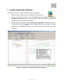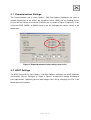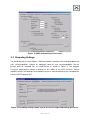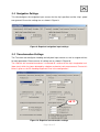
1
1 ADCP Installation Overview
1.1 Sensor Equipment
The following sensors are installed on the FS “Heincke”:
Table 1: Sensor specification
Sensor
Model
ADCP 150 kHz
Teledyne RDI
- vessel mounted -
OceanSurveyor
ADCP 600 kHz
Teledyne RDI
- portable for moon pool -
Workhorse
Inertial Navigation System
IXSea Phins
(INS)
Primary Positioning Unit
Trimble SP461
Secondary Positioning Unit
DEBEG/
Leica
Details from Manufacturer
Range: 400 m
Vertical resolution cell size: 4-8 m
Velocity accuracy: ±1.0%
Range: 50 m
Vertical resolution cell size: 2 m
Velocity accuracy: 0.3% of the water velocity
relative to the ADCP ±0.3cm/s
Heading accuracy: 0.05 deg (without aiding)
Roll, Pitch accuracy: 0.01 deg
Heave accuracy: 5 cm or 5%
Primary Positioning system DGPS
0.5 – 3 m accuracy
Secondary Positioning system GPS
5 – 15 m accuracy
This manual will currently focus on the 150 kHz vessel mounted ADCP.
1.2 Sensor Structure
Figure 1 shows the sensor structure of the ADCP hardware and Figure 2 shows the
installation in the laboratory. The 150 kHz transducer is hull mounted. Its deck unit is
permanently installed in the server rack next to the operator PC. The 600 kHz transducer is
portable. It has to be mounted in the moon pool. The installation of its deck unit has to be
done by AWI/FIELAX before the cruise. The operator PC receives ADCP data from one
ADCP deck unit at a time, position information from the GPS Debeg receiver OR the Trimble
DGPS receiver as well as attitude data (heading) from the Ixsea PHINS III Inertial navigation
system (INS). Only one of the two GPS receivers can be selected as the positioning input.
This can be done by a switch, which is installed on the bridge. However we recommend
using the Trimble GPS as it provides a more accurate position than the Debeg GPS so make
sure the switch is set accordingly. Recorded data should be regularly copied to the network
shares of the XDC storage server.
Page 3 of 15