1
University of Stuttgart
Diploma Thesis
Examiner:
Supervisor:
Prof. Dr. Hans-Joachim Wunderlich
Dr. Rainer Dorsch (hardware), Dr. Thomas Schöbel-Theuer (linux)
Begin:
End:
01.05.2002
31.10.2002/14.11.2002(extension)
CR-Classification: B.7.1 C.1 C.5 D.4
Dipoma Thesis Nr. 2013
Design of a
Memory Management Unit for
System-on-a-Chip Platform
"LEON"
Konrad Eisele
Division of Computer Architecture
Institute of Computer Science
Breitwiesenstr. 20-22
70565 Stuttgart
2
3
A Memory Management Unit (MMU) for SoC Platform LEON was designed and integrated
into LEON. The MMU comply to the SPARC Architectural Manual V8 reference MMU (SRMMU).
4
Contents
0.1
Abbreviation index . . . . . . . . . . . . . . . . . . . . . . . . . . . . . . . .
1 Introduction
7
9
2 Memory Management
2.1 Virtual Address Spaces . . . . . . . . . . . . . . . . . . . . . . . . . . . . . .
2.2 Paging and Segmentation . . . . . . . . . . . . . . . . . . . . . . . . . . . . .
2.3 Hardware support . . . . . . . . . . . . . . . . . . . . . . . . . . . . . . . . .
11
11
12
14
3 System-on-a-Chip platform LEON
3.1 LEON pipeline . . . . . . . .
3.2 Cache subsystem . . . . . . .
3.2.1 Data cache (DCache) .
3.2.2 Instruction cache . . .
3.2.3 AMBA ASB interface
.
.
.
.
.
15
16
17
18
18
20
.
.
.
.
23
23
23
23
24
.
.
.
.
.
.
.
.
.
27
27
28
29
31
32
32
32
32
32
6 Design options
6.1 Physically tagged / physically indexed (PTPI) . . . . . . . . . . . . . . . . . .
6.2 Physically tagged / virtually indexed (PTVI) . . . . . . . . . . . . . . . . . . .
35
35
35
.
.
.
.
.
.
.
.
.
.
.
.
.
.
.
.
.
.
.
.
.
.
.
.
.
.
.
.
.
.
.
.
.
.
.
4 SPARC standard
4.1 RISC . . . . . . . . . . . . . . . . . . . .
4.2 SPARC V8 . . . . . . . . . . . . . . . . .
4.2.1 Register windows . . . . . . . . . .
4.2.2 SPARC instruction overview . . .
.
.
.
.
.
.
.
.
.
.
.
.
.
.
.
.
.
.
.
.
.
.
.
.
.
.
.
5 SPARC V8 Reference MMU (SRMMU)
5.1 SPARC SRMMU translation overview . . . . . .
5.2 ASI: Alternate Space Instructions . . . . . . . .
5.2.1 ASI:MMU register access . . . . . . . .
5.2.2 ASI:flush/probe . . . . . . . . . . . . . .
5.2.2.1 flush . . . . . . . . . . . . . .
5.2.2.2 probe . . . . . . . . . . . . . .
5.2.3 ASI: MMU diagnostic access I/D TLB .
5.2.4 ASI: MMU physical address pass through
5.2.5 ASI: I/DCache flush . . . . . . . . . . .
5
.
.
.
.
.
.
.
.
.
.
.
.
.
.
.
.
.
.
.
.
.
.
.
.
.
.
.
.
.
.
.
.
.
.
.
.
.
.
.
.
.
.
.
.
.
.
.
.
.
.
.
.
.
.
.
.
.
.
.
.
.
.
.
.
.
.
.
.
.
.
.
.
.
.
.
.
.
.
.
.
.
.
.
.
.
.
.
.
.
.
.
.
.
.
.
.
.
.
.
.
.
.
.
.
.
.
.
.
.
.
.
.
.
.
.
.
.
.
.
.
.
.
.
.
.
.
.
.
.
.
.
.
.
.
.
.
.
.
.
.
.
.
.
.
.
.
.
.
.
.
.
.
.
.
.
.
.
.
.
.
.
.
.
.
.
.
.
.
.
.
.
.
.
.
.
.
.
.
.
.
.
.
.
.
.
.
.
.
.
.
.
.
.
.
.
.
.
.
.
.
.
.
.
.
.
.
.
.
.
.
.
.
.
.
.
.
.
.
.
.
.
.
.
.
.
.
.
.
.
.
.
.
.
.
.
.
.
.
.
.
.
.
.
.
.
.
.
.
.
.
.
.
.
.
.
.
.
.
.
.
.
.
.
.
.
.
.
.
.
.
CONTENTS
6
6.3
6.4
Virtually tagged / virtually indexed (VTVI) (SRMMU) . .
6.3.1 Writebuffer . . . . . . . . . . . . . . . . . . . . .
6.3.1.1 Virtual writebuffer . . . . . . . . . . . .
6.3.1.2 Physical writebuffer . . . . . . . . . . .
Design chosen . . . . . . . . . . . . . . . . . . . . . . . .
6.4.1 VTVI DCache, physical writebuffer (DCache.vhd)
6.4.2 VTVI ICache (ICache.vhd) . . . . . . . . . . . . .
6.4.3 Other changes made to LEON . . . . . . . . . . .
7 MMU design components
7.1 Functional overview . . . . . . . . . . . . . . . . . . . .
7.2 Component Overview . . . . . . . . . . . . . . . . . . .
7.2.1 Memory Management Unit (MMU) . . . . . . .
7.2.2 Translation Lookaside Buffer (TLB) . . . . . . .
7.2.3 Translation Lookaside Buffer Entry (TLBCAM)
7.2.4 Table Walk (TW) . . . . . . . . . . . . . . . . .
7.2.5 Least Recently Used (LRU & LRU entry) . . . .
7.3 Possible future optimizations . . . . . . . . . . . . . . .
7.3.1 1 cycle penalty implementation . . . . . . . . .
7.3.2 0 cycle penalty implementation . . . . . . . . .
7.3.3 Flush optimization . . . . . . . . . . . . . . . .
8 Design Flow
8.1 XESS XSV800 board development
8.1.1 Design flow . . . . . . . .
8.1.1.1 XESS board . .
8.1.1.2 Modelsim . . .
8.1.1.3 Synthesis . . . .
8.1.1.4 Software . . . .
.
.
.
.
.
.
.
.
.
.
.
.
.
.
.
.
.
.
9 Linux kernel
9.1 Linux file organization and make system
9.1.1 LEON dependent parts . . . . .
9.1.1.1 “make xconfig” . . .
9.1.1.2 “make vmlinux” . . .
9.2 Linux bootup . . . . . . . . . . . . . .
9.3 Memory . . . . . . . . . . . . . . . . .
9.3.1 Memory Management . . . . .
9.4 Processes . . . . . . . . . . . . . . . .
9.4.1 Process stack . . . . . . . . . .
9.4.2 Scheduling . . . . . . . . . . .
10 Appendix A: Components
.
.
.
.
.
.
.
.
.
.
.
.
.
.
.
.
.
.
.
.
.
.
.
.
.
.
.
.
.
.
.
.
.
.
.
.
.
.
.
.
.
.
.
.
.
.
.
.
.
.
.
.
.
.
.
.
.
.
.
.
.
.
.
.
.
.
.
.
.
.
.
.
.
.
.
.
.
.
.
.
.
.
.
.
.
.
.
.
.
.
.
.
.
.
.
.
.
.
.
.
.
.
.
.
.
.
.
.
.
.
.
.
.
.
.
.
.
.
.
.
.
.
.
.
.
.
.
.
.
.
.
.
.
.
.
.
.
.
.
.
.
.
.
.
.
.
.
.
.
.
.
.
.
.
.
.
.
.
.
.
.
.
.
.
.
.
.
.
.
.
.
.
.
.
.
.
.
.
.
.
.
.
.
.
.
.
.
.
.
.
.
.
.
.
.
.
.
.
.
.
.
.
.
.
.
.
.
.
.
.
.
.
.
.
.
.
.
.
.
.
.
.
.
.
.
.
.
.
.
.
.
.
.
.
.
.
.
.
.
.
.
.
.
.
.
.
.
.
.
.
.
.
.
.
.
.
.
.
.
.
.
.
.
.
.
.
.
.
.
.
.
.
.
.
.
.
.
.
.
.
.
.
.
.
.
.
.
.
.
.
.
.
.
.
.
.
.
.
.
.
.
.
.
.
.
.
.
.
.
.
.
.
.
.
.
.
.
.
.
.
.
.
.
.
.
.
.
.
.
.
.
.
.
.
.
.
.
.
.
.
.
.
.
.
.
.
.
.
.
.
.
.
.
.
.
.
.
.
.
.
.
.
.
.
.
.
.
.
.
.
.
.
.
.
.
.
.
.
.
.
.
.
.
.
.
.
.
.
.
.
.
.
.
.
.
.
.
.
.
.
.
.
.
.
.
.
.
.
.
.
.
.
.
.
.
.
.
.
.
.
.
.
.
.
.
.
.
.
.
.
.
.
.
.
.
.
.
.
.
.
.
.
.
.
.
.
.
.
.
.
.
.
.
.
.
.
.
.
.
.
.
.
.
.
.
.
.
.
.
.
.
.
.
.
.
.
.
.
.
.
.
.
.
.
.
.
.
.
.
.
.
.
.
.
.
.
.
.
.
.
.
.
.
.
.
.
.
.
.
.
.
.
.
.
.
.
.
.
.
.
.
.
.
.
.
.
.
.
.
37
37
37
38
38
40
40
40
.
.
.
.
.
.
.
.
.
.
.
43
45
50
50
50
50
51
51
51
51
51
53
.
.
.
.
.
.
55
55
55
56
56
57
57
.
.
.
.
.
.
.
.
.
.
61
62
63
63
63
64
65
66
67
67
68
73
0.1. ABBREVIATION INDEX
7
11 Appendix B: MMU distribution
11.1 Distribution overview . . . . . . . . . . . . . . . . . . . . . . . .
11.2 Subdirectory mmu/modelsim/ . . . . . . . . . . . . . . . . . . .
11.3 Subdirectory mmu/syn/ . . . . . . . . . . . . . . . . . . . . . . .
11.4 Subdirectory mmu/tbench/ . . . . . . . . . . . . . . . . . . . . .
11.4.1 Testbenches for MMU components mmu/tbench/comp . .
11.4.1.1 TLB_cam.vhd . . . . . . . . . . . . . . . . . .
11.4.1.2 tw_tb.vhd . . . . . . . . . . . . . . . . . . . .
11.4.1.3 TLB_tb.vhd . . . . . . . . . . . . . . . . . . .
11.4.1.4 mmu_tb.vhd . . . . . . . . . . . . . . . . . . .
11.5 Subdirectory mmu/scripts/ (XESS board development) . . . . . .
11.5.1 syn.pl: Xilinx tool chain build scripts . . . . . . . . . . .
11.5.2 selexo.sh : Handling the board . . . . . . . . . . . . . . .
11.6 Subdirectory mmu/tsource . . . . . . . . . . . . . . . . . . . . .
11.6.1 image: Creating page table hierarchies . . . . . . . . . . .
11.6.1.0.1 Analysing page table hierarchies . . .
11.6.1.0.2 Dumping memory content of testbench
11.6.2 Small Operating System (SOS) . . . . . . . . . . . . . .
11.7 Subdirectory mmu/vhdl/ . . . . . . . . . . . . . . . . . . . . . .
11.8 Subdirectory mmu/xess/ (XESS board development) . . . . . . .
.
.
.
.
.
.
.
.
.
.
.
.
.
.
.
.
.
.
.
79
79
79
80
80
80
80
80
80
80
81
81
82
82
83
84
85
85
86
86
12 Appendix C: MMU source
12.1 Source code . . . . . . . . . . . . . . . . . . . . . . . . . . . . . . . . . . . .
87
87
Bibliography
89
.
.
.
.
.
.
.
.
.
.
.
.
.
.
.
.
.
.
.
.
.
.
.
.
.
.
.
.
.
.
.
.
.
.
.
.
.
.
.
.
.
.
.
.
.
.
.
.
.
.
.
.
.
.
.
.
.
.
.
.
.
.
.
.
.
.
.
.
.
.
.
.
.
.
.
.
.
.
.
.
.
.
.
.
.
.
.
.
.
.
.
.
.
.
.
.
.
.
.
.
.
.
.
.
.
.
.
.
.
.
.
.
.
.
0.1 Abbreviation index
AMBA
API
ASB
ASI
CAM
CPLD
DCache
FPGA
IC
ICache
LRU
MMU
OS
PIPT
PTE
PTD
Advance Microcontroller Bus Architecture
Application Programming Interface
Advanced System Bus (AMBA)
Alternate Space Identifiers
Content Accessible Memory (full associative tag match)
Complex Programmable Logic Device
Data Cache
Field Programmable Gate Arrays
Integrated Circuit
Instruction Cache
Least Recently Used
Memory Management Unit
Operating System
Physically Indexed, Physically Tagged
Page Table Entry
Page Table Descriptor
8
RTOS
SoC
SPARC V8
SRMMU
TLB
VHDL
VIPT
VIVT
CONTENTS
Real Time Operating System
System on a Chip
SPARC architectural manual Volume 8
SPARC Reference MMU
Table Lookaside Buffer (PTE cache)
Very High Speed Integrated Circuit Hardware Description Language
Virtually Indexed, Physically Tagged
Virtually Indexed, Virtually Tagged
Chapter 1
Introduction
This diploma thesis is inspired by the idea to get a full feature Linux API running on the open
source System-on-a Chip (SoC) platform LEON, which is a synthesisable VHDL implementation of the SPARC Architectural Manual V8 standard. Linux has recently gained wide acceptance. With a rich literature footage and a broad spectrum of online documentation it is fairly
well understood. Porting Linux onto LEON was especially inviting because Linux has already
been ported to the SPARC architecture, running on Sun workstations 1 . However only SPARC
processors with a Memory Management Unit (MMU) are supported. The current LEON distribution does not include a MMU because LEON is targeted on embedded realtime applications,
where nondeterministic page faults of the MMU could cause trouble to the realtime requirements of these applications. Also in a deeply embedded environment, where normally only one
fixed task has to run, the overhead of Virtual Memory Management is quite significant. The
SPARC Architectural Manual V8 (SPARC V8) does not require a MMU to be present, however
the SPARC V8 (which the LEON integer unit implements) already defines a SPARC Reference
MMU (SRMMU). This suggested that when adding the SRMMU to LEON, porting Linux would
be a straightforward job. Therefore, the main goal of this diploma thesis is the implementation
of a SRMMU and it’s integration into the LEON SoC platform. This report will concentrate
on the hardware side: the design and implementation of a SRMMU. Running Linux on LEON
may not be practical for embedded realtime applications, nevertheless there could be quite a few
fields of application (PDA’s or the like). Another nice aspect is that Linux running on LEON
SoC would be Open Source from gate level on2 .
The MMU supports memory management in hardware. Chapter 2 gives an introduction to
the theoretical concepts of memory management. After that, chapter 3 gives a brief overview
over the SoC platform LEON, which had to be extended with a MMU. The LEON integer unit
implements the SPARC architecture according to the SPARC Architectural Manual V8, which is
described in Chapter 4. The SPARC Architectural Manual V8 does define a reference MMU in
Appendix H, the SRMMU, which is described in Chapter 5. The following chapters will focus
on the implementation of the MMU in hardware. Also the SRMMU suggests a specific design
in detail, there are nevertheless a variety of design options from which to choose. These options
are discussed in Chapter 6. Chapter 7 describes the actual implemented design, which is the
1
This source turned out to be well documented and, because of the RISC nature of the low level assembler parts,
relatively easy to understand
2
Of course excluding the tools for synthesis which are not open source (yet).
9
10
CHAPTER 1. INTRODUCTION
main part of this report: First a functional overview is given for the MMU as a whole, then for
each operation the MMU supports. Each design component of the MMU is described separately.
Some notes on future timing optimization follow. Chapter 8 will focus on the design flow, giving
an overview on the tools involved. Chapter 9 start with the Linux porting effort. It will describe
some fundamentals about the working of the Linux kernel and deal with aspects related to to
memory management in Linux, however for detailed descriptions refer to for instance to [5].
Because of the wide range of this diploma thesis, spanning from hardware design to kernel
hacking, naturally some parts will not be covered in full detail. Emphasis in this diploma thesis
was put on the practical side. The source distribution can be downloaded from [7].
Development was done on a XSV300 and 800 board with a Xilinx Virtex FPGA chip for
hardware prototyping.
Chapter 2
Memory Management
Historically Memory Management evolved out of the need implied by a multiuser/multitasking
environment [14]. In such an environment, where multiple users share one memory resource,
mechanisms has to be introduced to prohibit accidental access, that would crash the whole system, or unauthorized access, to protect private data. One of the first OS that pioneered the fundamental concepts of a multiuser/multitasking system was MULTICS , dating back to the late
’60. It implemented the concept of virtual addresses in hardware by 2 major techniques: paging
and segmentation [16]. These principles hold to date, most current architecture use paging or
segmentation or a combination of both.
A Virtual Memory Management scheme is defined by two main functions: translation and
protection. Translation dissolve the mapping of virtual addresses into physical addresses, which
in term is closely linked to memory allocation - where paging is somehow related to fixed size
allocation whereas segmentation is related to variable size allocation, each of which has its
advantages and disadvantages. The second function is protection. Each entity in paging and
segmentation hold access parameters which in turn reflect on the underlying physical resource.
The SPARC Memory Management architecture, which is the target of this diploma thesis, only
supports paging, therefore segmentation will only be covered briefly.
2.1 Virtual Address Spaces
Virtual addresses draws a clear border of abstraction. In a Virtual Memory Management scheme
the actual physical memory configuration is transparent to the running program. A distinct feature of this is that programs can be programmed for an address space at compile time that is
actually larger than the physical address space at runtime. The uniformity frees the programmer
of memory considerations. The seamless integration of other resources than memory, such as
files, reduce system and hardware dependencies [14]. Two of the main techniques for implementing virtual address spaces in hardware are paging and segmentation, which are discussed
in the following sections.
11
CHAPTER 2. MEMORY MANAGEMENT
12
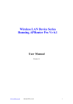
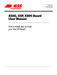
2.2 Paging and Segmentation
Paging use fixed size pages as base unit, usually 4k large. It provides one virtual address space
in the logical domain, which is mapped to physical memory through one mapping entry for
each page in the virtual address space, which is shown in figure 2.1. Each mapping entry holds
additional information for OS use. This is shown in figure 2.1.
Linear address space
1
2
3
4
n
5
Logical level
Physical Level
Mapping
1
2
3
4
Figure 2.1: Paging
Segmentation on the other hand side uses variable size segments. Each segment form one
independent virtual address space, however only one mapping per segment is provided, therefore
a segment has to be contiguous in physical memory. Each segment holds additional information,
which include its length and flags for OS use. This is shown in figure 2.2.
Linear address space
1
Linear address space
3
Linear
address
space
2
Logical level
Mapping
Physical level
Linear Address Space
Linear Address Space
Linear
address
space
Figure 2.2: Segmentation
The paging example figure 2.1 shows a mapping (1,1) (2,3) (4,2). Adjacent pages in the
virtual address space can be scattered in physical memory. This makes memory allocation in
paging immune to fragmentation. Paging forms the base for swapping (demand paging) of the
OS, where not the whole virtual address space has to be constantly present in physical memory.
Pages can be swapped in/out from hard disc on demand. The corresponding flags in the page
table entries keep track on this process.
Both paging and segmentation map from virtual addresses to physical addresses. For the
translation several data structures are possible to store the mapping: It can for example be done
by using one big flat table. In this case the virtual address form an offset into the table where the
corresponding descriptor for the physical address is found. For the above paging example this
would look somehow like this:
2.2. PAGING AND SEGMENTATION
13
virtual index physical
1
1
2
3
3
4
2
5
...
...
...
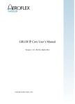
In case of segmentation a segment it is called a segment descriptor table. In case of paging
it is called a page table. In case of paging with one flat page table a 2**32 virtual address
space with 4k size pages would require 2**20 entries, which would occupy around 4 MB 1 [23].
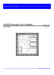
Therefore in most cases a sparse page table hierarchy is used. An example of this can later be
seen in section 5. In a page table hierarchy the virtual address is subdivided into several indices,
that does each offset into the next level of the page table tree. By interrupting the traversal in
between, it is also possible to define larger pages (than the fixed size 4k pages). For instance in
the SPARC page table tree with 4 levels, level 0 maps 4G bytes (whole virtual address space),
level 1 maps 16M, level 2 maps 256K of memory and level 3 maps the standard 4K pages.
Figure 2.3 shows a schematic of the page table traversal.
Virtual address
Miss
Main memory
(table lookup)
TLB
Hit
No
Yes
Store
in TLB
last
level of
hirarchy?
Yes
Protection violation
exception
Access
authorized
mode?
Item
present
in memory?
Mapping descriptor
No
Page fault exception
Physical address
Fetch from disc
Figure 2.3: Page table hierarchy traversal.
(Related to [14])
Along the physical memory address the page table entries store additional flags, which enable the operating system to swap unused pages out of physical memory onto disk and implement protection on pages. In paging only one hardware implemented logical entity exist.
Therefore protection in paging must be done by subdividing the entire virtual address space into
attributed regions, merely setting another layer on top. This subdivision can only be done in the
1
On 64-bit computers this would even increase to 2**52 entries which is not tolerable at all, therefore another
data structure instead of a lookup table has to be used, for instance a inverted page table, which is a hash [23].
CHAPTER 2. MEMORY MANAGEMENT
14
granularity defined by the page size (usually 4k) and is limited by the fact that these regions are
bound to one virtual address space (overlapping may occur)[23]. The sub partitioning into different protected regions is partly done at compile time2 . On the other hand side in segmentation
each segment form a logical entity with its own rights3 .
2.3 Hardware support
Hardware support include
Table Lookaside Buffer (page table entries cache)
Updating page table entries flags
Exception signals
Table walk
The most primitive form of translation would be to raise an exception on every memory access
and let the OS do the translation from virtual to physical addresses in software. Hardware support accelerates this process by adding the Table Lookaside Buffer (TLB), which is in principle
a cache of previous successful translations. In most cases it is build as a full-associative cache.
With an appropriate processor design that tightly integrates the TLB into the overall structure
the translation can be done without any delay on a TLB hit. In the course of this diploma thesis
it became clear that it is hard to add a TLB with zero wait states to a design previously not
designed with a MMU in mind.
On a TLB miss the page tables has to be traversed (Table walk). This can be done in hardware
or in software. The advantage of a software TLB miss handle could be that an advanced TLB
updating scheme could be implemented to minimize TLB misses. Nevertheless TLBs generally
have a high hit ratio.
Additional hardware support is provided by updating the referenced and modified flags of a
page table entry and checking access permissions. The referenced flag logs any accesses to the
page, the modified flag logs write accesses to a page. These flags in turn will be used by the OS
on swapping operations. On a privilege or protection violation the hardware raises a signal that
cause the processor to trap.
2
Or dynamically using the mmap() call in Linux.
Another interesting feature of segmentation is the possibility of dynamic linking at runtime, a feature proposed
by the late MINICS architecture. In a segmented Memory Management scheme a function would be a segment
with the appropriate access rights. A jump to function n would equal in jumping to the offset 0 of segment n. If
any program uses a distinct n at compile time relinking a new function for all running programs in the running
system would be possible by exchanging the segment descriptor in the segment descriptor table at position n. No
re-compilation of programs or rebooting of the whole system would necessary [23].
3
Chapter 3
System-on-a-Chip platform LEON
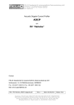
This chapter gives an overview of the LEON architecture. When adding a MMU to LEON, it
had to be placed somewhere between the integer unit, the instruction cache (ICache), the data
cache (DCache), and the AMBA memory interface. After giving a brief overview over the
global LEON system architecture the interaction of the LEON pipeline with the DCache and
ICache will be presented in more detail. Figure 3.1 shows a simplified overview of the LEON
architecture.
Integer Unit
(iu.vhd)
Debug
Support
Unit
Data Cache Instruction Cache MMU
(dcache.vhd)
(icache.vhd)
(mmu.vhd)
Amba Interface
(dsu.vhd)
(acache.vhd)
AMBA Arbiter
Advanced High Performancs Bus (AHB)
(ahbarb.vhd)
Advanced Peripheral Bus (AHB)
AHB/APB Bridge
Debug
Serial
Link
IRQ
Memory controller
(irqctrl.vhd)
Timer
(bpbmst.vhd)
(timers.vhd)
(mctrl.vhd)
I/O Ports
(dcom.vhd)
(ioport.vhd)
UARTs
(uart.vhd)
(mcore.vhd)
UART
PROM I/O SRAM SDRAM
PI/O Ports, UART
Figure 3.1: Simplified LEON overview
The LEON source distribution is a synthesisable VHDL implementation of the SPARC Architectural Manual V8 standard. It was developed by Jiri Gaisler and can be downloaded from
[8]. It is provided under the GNU Public License (GPL) [10]. It’s main features are
Integer unit
Floating point unit
On-chip AMBA bus (making it easy to integrate custom ip blocks into the system)
15
CHAPTER 3. SYSTEM-ON-A-CHIP PLATFORM LEON
16
Cache subsystem
Hardware debug unit
Memory controller
UART
On the software side the following packages are available:
RTEMS Real Time Operating System (RTOS) [3, 8] , which features a Posix API. RTEMS
is currently the standard application platform for programs running on LEON.
Just recently a port of the eCos RTOS from RedHat Inc. [11] had been announced by Jiri
Gaisler [8], which features a compatibility layer EL/IX that implements a POSIX API and
some of the Linux APIs. 1
uCLinux OS port for LEON [17][24], which is a OS based on Linux that supports processors with no MMU.
lecc: GNU based cross compilation system
tsim: LEON simulator
3.1 LEON pipeline
The LEON integer unit (IU) implements SPARC integer instructions as defined in SPARC Architecture Manual V8. It is a new implementation, not based on previous designs. The implementation is focused on portability and low complexity, nevertheless it is very tightly woven,
making it hard to integrate new features (and understand the source code). The LEON pipeline
is a 5 level pipeline: fetch, decode, execute, memory and write back stage. [18]
FE (Instruction Fetch): If the instruction cache is enabled, the instruction is fetched from
the instruction cache. Otherwise, the fetch is forwarded to the memory controller. The
instruction is valid at the end of this stage and is latched inside the IU.
DE (Decode): The instruction is decoded and the operands are read. Operands may come
from the register file or from internal data bypasses. CALL and Branch target addresses
are generated in this stage.
EX (Execute): ALU, logical, and shift operations are performed. For memory operations
(e.g., LD) and for JMPL/RETT, the address is generated.
1
Real Time Operating Systems like eCos and RTEMS are aimed on a system with small memory footage and
realtime requirements suitable for deeply embedded applications. For instance a simple “Hello world!” application
with the RTEMS RTOS linked to it would require 133k of memory and can easily be place into ROM. Embedded applications running on a RTOS typically handle fixed tasks in signal processing or in the industrial process
measurement and control environment, like finite state machines for control flow or detecting faults. The current
non-MMU LEON is designed for such an realtime environment where the RTOS has to be as slim as possible.
3.2. CACHE SUBSYSTEM
17
Decode
Execute
Memory
MAddress
EData
EAddress
MAddress
EData
EAddress
MAddress
2 decode cycles STORE
EAddress
1 cycle decode LOAD
EData
The above figure show a ld (word) and st(word) command on a DCache hit. The load command will
take 1 execution cycle to process, in the execution stage the EAddress will be generated (row 2). The
store command will take 2 execution stage cycles to process, in the first cycle (row 2) the EAddress is
generated (that will then move into MAddress of memory stage), in the second cycle (row 3) EData (the
value to store) is retrieved from the register file. The store will initialize the writebuffer, which will drive
the memory request so that the pipeline can continue operation.
Figure 3.1.1: Load/Store commands
ME (Memory): Data cache is accessed. For cache read hit, the data will be valid by the
end of this stage, at which point it is aligned as appropriate. Store data on a cache hit read
out in the E-stage (2 cycle execution stage command) is written to the data cache at this
time.
WR (Write): The result of any ALU, logical, shift, or cache read operations are written
back to the register file. [18]
In principle every command takes 5 cycles to finish if no stalls occur, however the decode and
execution stage are multi cycle stages that can take up to 3 cycles, for instance the store double
(ldd) command would remain 3 cycles in the execution stage before pipeline continues. Memory
access from data cache is initiated through the load (ld), store (st), load alternate (lda), store
alternate (sta) and the atomic loadstore (ldst) and swap (swap) commands in the memory
stage. Figure 3.1.1 shows a 1 cycle execution stage load (ld), and a 2 cycle execution stage store
(st) command.
3.2 Cache subsystem
The LEON processor implements a Harvard architecture with separate instruction and data
buses, connected to two independent cache controllers. Both data cache (DCache) and instruc-
CHAPTER 3. SYSTEM-ON-A-CHIP PLATFORM LEON
18
EData
EAddress
MAddress
1
addr
data in
Cachemem
data out
3
align
tag out
= pipeline hold
011
merge
hit
4
001
100
2
WB
Waiting Load
3 decode cycles
Memory
data out
110
Load
Double Load
Idle
Idle
Store
Store
Store pending
In the above figure address that drives the cachemem comes either from execution stage or from memory
stage (1). Both read and write commands share a single writebuffer to issue memory requests (2) therefore
read and write commands have to wait until the writebuffer empties, in which case the pipeline stalls. On
a read the pipeline will of course wait for the result to be returned from memory. On a store the pipeline
will stall until the writebuffer is empty. The memory result will be aligned (3) and is merged into the
current cache line (4).
Figure 3.2.1: LEON DCache schematic and state transition diagram
tion cache (ICache) share one single Advanced Microcontroller Bus Architecture (AMBA) Advanced System Performance Bus (ASB) master interface to access the memory controller.
3.2.1 Data cache (DCache)
The LEON DCache is a direct-mapped cache, configurable to 1 - 64 kbyte. It has a one element
writebuffer that operates in parallel to the pipeline after a store operation has initialized it. The
write policy for stores is write-through with no-allocate on write-miss. The data cache is divided
into cache lines of 8 - 32 bytes. Each line has a cache tag associated with it, containing a tag
field and one valid bit per 4-byte sub-block [18]. A simplified DCache schematic is shown in
figure 3.2.1.
Figure 3.2.2 shows the DCache miss behavior. This part is especially important to understand because the MMU’s address translation will have to be done here.
3.2.2 Instruction cache
The LEON instruction cache is a direct-mapped cache, configurable to 1 - 64 kbyte. The instruction cache is divided into cache lines with 8 - 32 bytes of data. Each line has a cache tag
associated with it consisting of a tag field and one valid bit for each 4-byte sub-block [18]. A
simplified ICache schematic is shown in figure 3.2.3.
Figure 3.2.4 shows the ICache behavior on a miss. ICache will change into streaming mode,
fetching one entire cache line. Because the configurable cache line size is a power of 2 and
smaller than the 4k page size this operation will not cross a page boundary. Therefore only one
3.2. CACHE SUBSYSTEM
19
2
tag appears
Decode
1 addr calc
Execution
Memory
dcache state change
Write
4
3 miss detect
Execution Memory
Write
no pipeline transition
5
6 amba request
Write
Memory
mem ready, latch data using dco.mds
7
8
save to regfile (falling)
pipeline continues
Memory
Write
9
The address is calculated in the execution stage (1) which will enter DCache and will be forwarded to
cache’s syncram to retrieve the tag. Address is either register+register or register+immediate. The tag
from sycram will become valid at the beginning of the memory stage (2). In the memory stage the miss
detect is made, meaning that the tag is compared with the address (3). If a miss is detected (not equal)
DCache will change its state at the beginning of write stage (4) and will stall the pipeline (5) This implies
that, if the following command (now in memory stage) is also a load, one wait state has to be inserted to
retrieve the tag for that command after the current memory command has written its value to the cache’s
syncram. The memory command will therefore stall in write stage while the memory request is issued
(6). When result is ready it is strobed into the pipeline on the dco.mds signal, bypassing the normal
pipeline propagation (pipeline still stalls) (7). The result is saved to the register file on the falling edge of
write stage after which the pipeline can continue (8).
Figure 3.2.2: DCache miss pipeline behaviour on a load comand
CHAPTER 3. SYSTEM-ON-A-CHIP PLATFORM LEON
20
R−pc
F−pc
2
waddr
1
addr
data in
Cachemem
data out
tag out
hit
line end
addr
Memory
0
data out
= streaming
1
miss
On a ICache miss the ICache will change into streaming mode. The waddr buffer will hold the next
memory address to retrieve (1). On each command that has been retrieved waddr will be incremented.
(2)
Figure 3.2.3: LEON ICache schematic
translation has to be done when changing into streaming mode.
3.2.3 AMBA ASB interface
Data and instruction cache have to share one single AMBA ASB master interface. Serializing
the concurrent ICache and DCache requests is done by the ACache component. A simplified
ASB query is shown in the figure 3.2.
Request
Wait
addr
addr out
data
data out
grant
ready
data in
data
Figure 3.2: Simplified ASB query
AMBA
Cache
req
3.2. CACHE SUBSYSTEM
21
2
1 miss detect
Fetch
icache state change, streaming
Decode
4
no pipeline transition, icache blocking
3 amba request
Fetch
Decode
5
mem ready, latch data using ico.mds
6
decode
Decode
Fetch
8
Fetch
no pipeline transition, icache blocking
7 amba request
Decode Execution
Memory
9
mem ready, latch data using ico.mds
10
decode
Fetch
Decode
11
Fetch
Decode
pipeline continues
Execution
pipeline continues
Execution
Memory
no pipeline transition, icache blocking
Execution
Memory
Write
=Command1
=Command2
The instruction address will either be calculated in execution stage from a previous branch or jump command or by normal increment of the pc. It is valid at the beginning of the fetch stage and will be used to
retrieve the tag. The miss detect is made in fetch stage (1), if a miss was detected the ICache will change
into streaming mode (2) and issue a memory request (3) while the pipeline stalls in the decode stage,
waiting for a command (4). If the memory request returns, the result is strobed by the ici.mds signal
into the pipeline, bypassing the normal pipeline propagation (pipeline still stalls) (5). Now the decode
stage will get valid and can propagate one step at the next clock cycle (6). Meanwhile the ICache (that is
still in streaming mode) issues the next memory request (7). Until it arrives the pipeline stalls again (8).
(9),(10),(11) repeat this pattern.
Figure 3.2.4: ICache miss pipeline behaviour
22
CHAPTER 3. SYSTEM-ON-A-CHIP PLATFORM LEON
Chapter 4
SPARC standard
The LEON integer unit implements the SPARC Architecture Manual V8 standard. This chapter
tries to give a brief overview of it’s RISC nature. For the details refer to [21].
4.1 RISC
Other than the CISC architectures, which where developed by commercial companies, the RISC
architecture emerged from a research and academic surrounding [19]. The RISC key phrase
was coined by the Berkeley RISC I + II project, led by David Patterson at UC Berkeley dating
back to 1980. The RISC I architecture later became the foundation of Sun Microsystems’s [13]
SPARC V7 standard, commercialized by SPARC International Inc. [20]. Another famous RISC
architecture that resembles this development is the MIPS machine, developed at Stanford led by
John Hennessy, later commercialized by MIPS Technologies Inc [15].
4.2 SPARC V8
The current version 8 (V8) of the SPARC standard was first published in 1990 and can be
downloaded from [21]. Like other reduced instruction set (RISC) architectures it’s features
include a fixed size instruction format with few addressing modes and a large register file. The
distinctive feature of SPARC is it’s “windowed” register file, where the instruction’s source and
destination register addresses are offseted by the “Current Window Pointer” , this way a large
pool of fast registers can be accessed, while still keeping the instruction size small.
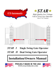
4.2.1 Register windows
Figure 4.1 illustrates the register windows for a configuration with 8 windows. The register
windows are divided into 3 parts: ins, local and outs. On a SAVE instruction, which adds 1
to the Current Window Pointer (CWP), the current window’s “outs” will get the new window’s
“ins”, on a RESTORE, which subtracts 1 from the CWP, it’s vice versa. On the wraparound
point one invalid window exist (window 7 in the above figure). This window is marked by the
Window Invalid Mask (WIM). It is invalid because it’s “out” registers would overwrite the “ins”
23
CHAPTER 4. SPARC STANDARD
24
Win
do
w
ins
outs
1
Win
do
w
outs
)
IM
local
7(
W
local
ins
local
dow 0
Win
outs
ins
local
dow 2
Win
outs
SAVE
RESTORE
CWP-1
CWP+1
ins
dow 6
Win
ins
outs
dow 4
Win
local
ins
local
5
outs
local
ins
Win
do
w
outs
local
outs
ins
Wi
n
d
ow
3
Figure 4.1: SPARC register windows (taken from [21] p.27)
of it’s neighbor which is not desirable, therefore moving into a invalid marked window will
cause a trap. Typically the trap handler will take care of swapping the registers onto the stack.
The “local” registers are registers that are visible only to the current function, while the “ins”
and “outs” are shared between caller and callee1 .
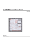
4.2.2 SPARC instruction overview
All SPARC instruction are 32 bit wide. For the MMU design mainly instructions for memory
access are relevant. For memory access only few “load to register” and “store from register”
commands are available. The destination (for stores) and source (for loads) addressing mode
is register indirect with an optional offset (either immediate or register). This enables a simple
pipeline with only one memory stage. A reference to a absolute memory address will take up
to 3 instructions, two instructions for initializing the address register (load lower 13 bit and
load upper 19 bit) and one for the memory operation. If a base pointer is already loaded into a
register (like the stack pointer) a reference will take only one instruction if a immediate offset
is used, two instructions if a register has to be first loaded with the offset. Figure 4.2 gives
an instruction layout overview. There are 3 main formats: Format 1 represent absolute jumps,
format 2 represent the command for initializing the upper part of a 32 bit register (SETHI) and
for conditional branches, format 3 represent the remaining arithmetic and control commands.
1
The callee has to issue a SAVE at the beginning and a RESTORE at the end when returning.
4.2. SPARC V8
25
Format 1 (op=1): CALL
op
disp30
31 30 29
0
Format 2 (op=0): SETHI & branches
op
rd
31 30 29
op
op2
25 24
a
cond
31 30 29 28
imm22
22 21
0
op2
25 24
disp22
22 21
0
Format 3 (op=2 or 3): Remaining instructions
op
rd
31 30 29
op
rd
31 30 29
op
31 30 29
op3
25 24
rs1
19 18
op3
25 24
rd
rs1
19 18
op3
25 24
opf
i=0
14
rs1
19 18
rs2
14 13
asi
0
rs2
13 12
i=1
14
5 4
5 4
0
simm13
13 12
Figure 4.2: SPARC instruction overview (taken from [21] p.44)
0
26
CHAPTER 4. SPARC STANDARD
Chapter 5
SPARC V8 Reference MMU (SRMMU)
The MMU for LEON that is the target of this diploma thesis implements a MMU that is compliant to the SPARC Reference MMU (SRMMU): The SPARC Architecture Manual V8[21] does
not require a MMU to be present, the standard rather specifies a reference MMU in Appendix
H that is optional to implemented. However all commercial SPARC V8 implementation follow
the SRMMU suggestion. The main features of SRMMU are:
32-bit virtual address
36-bit physical address
Fixed 4K-byte page size
Support for sparse address spaces with 3-level map
Support for large linear mappings (4K, 256K, 16M, 4G bytes)
Support for multiple contexts
Page-level protections
Hardware miss processing (Table Walk)
The following sections will give an overview. For more information refer to [21].
5.1 SPARC SRMMU translation overview
Figure 5.1 gives an detailed overview of the translation process and the data structures that are
involved.
The first level of the page table hierarchy is that of the Context Table (1) . It is indexed by the
Context Number (CTXNR), a register that is initialized with a unique number that is associated
to each process. On a process switch this register has to be updated 1 . The 1-4 levels of the page
1
The Context Number together with the virtual address form the Cache’s tag, this way cache synonyms are
avoided (different processes that use the same virtual address for different physical mappings). The use of the
Context Number in the SRMMU suggests that the Caches should be virtually tagged / virtually indexed, which is
described in Chapter 6 in more detail.
27
CHAPTER 5. SPARC V8 REFERENCE MMU (SRMMU)
28
1
CTP
(context table pointer)
align
Context Table Pointer
11 10
31
rsvd
2 1 0
CTXNR
Context Number
8
0 (context number)
Level 1
31
Level 2
24 23
Level 3
18 17
VAddr
Offset
12 11
0
2
PTD/PTE
PTD/PTE
PTD/PTE
PTE
3
PTD
(page table descriptor)
Page Table Pointer
31
PTE
(page table entry)
8 7
Physical Page Number
31
6
ET
2 1 0
C M R ACC ET
8 7 6 5 4 2 1 0
Physical Page Number
35
5 4
4
PAddr
Offset
12 11
0
Figure 5.1: Translation overview
table hierarchy (2) are indexed through the different parts of the virtual address. If a Page Table
Descriptor (PTD) is found when indexing into the Page Table, the next level is traversed, if a
Page Table Entry (PTE) is found the traversal is completed. PTE and PTD are distinguished by
the ET field (3), where ET=1 indicates PTD and ET=2 indicates PTE, ET=0 indicates a missing
entry (page fault). Level 1 PTE (context) map to 4 GB, level 2 PTE (region) map to 16 MB, level
3 PTE (segment) map to 256k and level 4 PTE (page) map to 4k. The PTE entry includes the
Physical Page Number and additional flags for protection, cache-ability and referenced/modified
accounting. The physical address (4) that is the result of the translation of the MMU is formed
out of the Physical Page Number and the Offset (the sizes vary depending on the page table
hierarchy level).
5.2 ASI: Alternate Space Instructions
The privileged versions of the load/store integer instructions (ld/st), the load/store alternate
instructions (lda/sta), can directly specify an arbitrary 8-bit address space identifier (ASI) for
the load/store data access. The privileged alternate space load/store instructions take the form:
“lda [addr] asi_ident,%r” and “sta %r,[addr] asi_ident”, where asi_ident is the 8 bit
ASI identifier. The address and the value (in case of a store) are interpreted in a specific way
that differ for each ASI identifier2 . The privileged load/store alternate instructions can be used
by supervisor software to access special protected registers, such as MMU, cache control, and
2
For instance for ASI identifiers “DCache_flush” on a store to any address DCache is flushed. In other ASI
identifier spaces addresses are mapped to special registers, that can be stored or loaded just like normal memory.
5.2. ASI: ALTERNATE SPACE INSTRUCTIONS
29
processor state registers, and other processor or system dependent values [21]. For the MMU
the SPARC Architecture Manual V8 suggests the ASI “MMU register” (0x4) , ASI “MMU
flush/probe” (0x3), ASI “MMU bypass” and a optional ASI “MMU diagnostic access I/D TLB”
(0x7). For fine grade cache flushing (flushing depending on ctx number and a virtual address
pattern) five additional “I/DCache flush” ASIs are suggested.
5.2.1 ASI:MMU register access
Alternate space “MMU register” gives access to the MMU’s control registers. The instructions
“lda [addr] asi_mmureg,%r” and “sta %r,[addr] asi_mmureg” behave as you would expect. For detailed information refer to [21] Appendix H. There are 5 registers defined for the
SRMMU:
[addr]
0x0xx
0x1xx
0x2xx
0x3xx
0x4xx
register
Control Register
Context Table Pointer
Context Number Register
Fault Status Register
Fault Address Register
Control Register: This register include enable flag and implementation specific flags
among others.
IMPL
Ver
31
28 27
24 23
Custom
8
PSO
resvd
NF
7 6
2 1
E
0
– IMPL: MMU Implementation.
– VER: MMU Version .
– SC: System control.
– PSO: Partial Store Order.
– NF No Fault bit, disable fault=1 trap.
– E Enable, enable = 1.
Context Pointer register: This register holds the root of the page table tree.
virtual address
31
resvd
2 1
0
CHAPTER 5. SPARC V8 REFERENCE MMU (SRMMU)
30
Context Number register: This register stores the context number of the running process. It will form the offset into the context table.
Context Number
31
0
Fault status register: This register holds the status of the MMU on a exception (i.e. page
fault).
reserved
31
EBE
L
18 17
10 9
AT
8 7
FT
5 4
2
FAV OW
1
0
– EBE: unused
– L: The Level field is set to the page table level of the entry which caused the fault:
L
0
1
2
3
Level
Entry in Context Table
Entry in Level-1 Page
Entry in Level-2 Page
Entry in Level-3 Page
– AT: The Access Type field defines the type of access which caused the fault:
AT
0
1
2
3
4
5
6
7
Access Type
Load from User Data Space
Load from Supervisor Data Space
Load/Execute from User Instruction Space
Load/Execute from Supervisor Instruction Space
Store to User Data Space
Store to Supervisor Data Space
Store to User Instruction Space
Store to Supervisor Instruction Space
– FT: The Fault Type field defines the type of the current fault:
5.2. ASI: ALTERNATE SPACE INSTRUCTIONS
FT
0
1
2
3
4
5
6
7
31
Fault type
None
Invalid address error
Protection error
Privilege violation error
Translation error
Access bus error
Internal error
Reserved
Fault address register: This register holds the virtual address that caused the exception:
virtual address
31
0
5.2.2 ASI:flush/probe
Alternate space “flush/probe” gives access to the MMU’s translation process and the TLB. A
read access to ASI “flush/probe” will initiate a probe operation, either returning the PTE or
zero3 - a write access will initiate a flush operation, that will remove entries form the TLB. The
flush/probe criteria is coded into the write/read address and has different meanings for flush and
probe. It has the following format:
Virtual Flush Probe Address
31
type
12 11
reserved
8 7
0
Virtual Flush/probe address: The index part of the virtual address.
Type:
Type
0 (page)
1 (segment)
2 (region)
3 (context)
4 (entire)
5 - 0xF none
Probe
probe until Level-3 entry
probe until Level-2 entry
probe until Level-1 entry
probe until Level-0 entry
probe until Level-n entry
Flush
flush Level-3 PTE
flush Level-2 & 3 PTE/PTDs
flush Level-1, 2 & 3 PTE/PTDs
flush Level-0, 1, 2, & 3 PTE/PTDs
flush all PTEs/PTDs
3
Probe operation will return the PTE of the page table hierarchy, not the physical address the is coded into the
PTE. The probe operation can also be done in software, using the ASI “MMU physical address pass through” and
traversing the page table hierarchy by hand. In fact the probe operation is rarely used.
CHAPTER 5. SPARC V8 REFERENCE MMU (SRMMU)
32
5.2.2.1 flush
A flush operation takes the form “sta %r, [addr] asi_flush_probe”, where data supplied
in %r is ignored and addr forms the flush criteria (see above). Entries from the TLB satisfy the
given criteria are flushed. For detailed information refer to [21] Appendix H, p. 250.
5.2.2.2 probe
A probe operation takes the form “lda [addr] asi_flush_probe,%r”, where addr forms the
probe criteria (see above) . The return value is either the PTE or zero. For detailed information
refer to [21] Appendix H, p. 250.
probe Type
0(page)
1(segment)
2(region)
3(context)
4(entire)
5-0xf
Level 0
2 3 0 1
Level 1
2 3 0 1
Level 2
2 3 0 1
Level 3
2 3 0 1
0
0
0
*
*
0
0
*
0
*
0
0
0
0
0
0
0
0
*
0
=>
=>
=>
*
=>
0
0
0
0
0
*
=>
=>
*
0
0
0
=> * 0
undefined
*
0
0
*
=>
*
*
0
=>
*
0
*
0
0
0
-
0
*=value, 0=zero, “=>”= follow [21]
5.2.3 ASI: MMU diagnostic access I/D TLB
Alternate space “MMU diagnostic access I/D TLB” gives direct read/write access to the TLB.
This ASI is not intended for system operation but for system debugging only. It is not required
to be implemented. The SRMMU specification gives a suggestion of the coding of the address/data supplied by the “lda [addr] asi_iodiag,%r” and “sta %r,[addr] asi_iodiag”
command, however these are highly implementation specific. The method implemented in this
diploma thesis simply reads out the whole TLB entries content to ram using the AMBA interface
already connecting the TLB for write-back of page table entries who’s referenced or modified
bits has changed. This ASI can be removed when system has proven to works properly. Write
operation on TLB is not supported.
5.2.4 ASI: MMU physical address pass through
Alternate Load/Store with the ASI “MMU physical address pass through” bypass the MMU
translation, i.e. this can used to modify the page table hierarchy on bootup. The original SPARC
suggestion for this ASI is 0x20-0x2f. For detailed information refer to [21] Appendix I, p. 267.
5.2.5 ASI: I/DCache flush
This ASI affects the cache itself (not the TLB). This ASI is used by Linux and is thus added
to the DCache controller’s ASI decoder. A alternate Store with the Alternate Space Identifier
5.2. ASI: ALTERNATE SPACE INSTRUCTIONS
33
“I/DCache flush” will flush I/DCache entries given a specific criteria. For detailed information refer to [21] Appendix I, p. 266. In the current implementation any alternate store to ASI
“I/DCache flush” will flush the whole I/DCache, a future enhancement could be the implementation of a fine grade flush that is suggested by the SPARC standard.
34
CHAPTER 5. SPARC V8 REFERENCE MMU (SRMMU)
Chapter 6
Design options
There are several possibilities for implementing a MMU for LEON, each of which would have
to be integrated into a different place of the current design. For the cache/MMU integration any
of the three alternatives, “physically tagged and physically indexed” (PTPI), “virtually tagged
and physically indexed” (VTPI), and “virtually tagged and virtually indexed” (VTVI) has its
drawbacks and advantages that are discussed in the following chapter. The SRMMU actually
suggests to use a the VTVI design by introducing the Context Number register, however also a
PTPI or VTPI design could be implemented that complies to the SRMMU standard.
In a VTVI design there are again 2 choices to choose from: virtual writebuffer (translation
after initialization of writebuffer) or physical writebuffer (translation before initialization of
writebuffer). The VTVI design with a physical writebuffer and a combined I/DCache TLB is
the most simple design to implement.
6.1 Physically tagged / physically indexed (PTPI)
On a PTPI design one TLB lookup has to be made on every cache access. This requires the TLB
lookup to be integrated into the pipeline to get reasonable performance. In a PTPI design shared
pages among different processes are possible (with any virtual address mapping), which means
sharing of cache line among different tasks is possible. Cache snooping is possible 1 . A PTPI
integration is shown in figure 6.1.
Implementing such a scheme into LEON would be difficult because it would mean in fact to
rewrite the pipeline. An advantage would be that DCache and ICache could be left unchanged,
with snooping enabled.
6.2 Physically tagged / virtually indexed (PTVI)
The PTVI design combines the physical with the virtual cache design: The drawback of a pure
physical cache is that the TLB lookup has to be done before every cache access, the drawback
of s pure virtual cache design is that context information has to be added to avoid the synonym
1
In Cache Snooping the AMBA Bus is constantly checked to see weather another AMBA Bus Master is modifying a memory location which is stored in the Cache
35
CHAPTER 6. DESIGN OPTIONS
36
icache tlb
FE
DE
dcache
EX
ME
tlb
instruction
cache
WB
data cache
Figure 6.1: Pipeline with physically tagged and physically indexed cache
problem (see section 6.3). The PTVI design still has to do a TLB lookup on every cache access,
but because the cache index is virtual the tag retrieval can be initiated right away while the
TLB lookup is done in parallel. Because the tag is physical no synonyms can occur, therefore
no context information is needed. This also means that sharing cache line among different
processes is possible (yet the virtual addresses mappings have to be equal 2 ). Cache snooping is
not possible. Therefore on a memory access by another AMBA master Cache integrity has to be
maintained my software. A PTVI integration is shown in figure 6.2.
FE
DE
ME
EX
virtual index
virtual index
icache
WB
instruction cache
tlb
data cache
dcache
tlb
tag
tag
data
pysical tag
pysical tag
hit
hit
data
Figure 6.2: Pipeline with virtually tagged and physically indexed cache
Because the TLB lookup has to be done in one cycle (until the tag arrives) either a dual port
syncram or a split instruction/data cache has to be implemented so that instruction/data cache
can work in parallel. Integration could be done in ICache and DCache with minor changes in
the cache - pipeline inter-working.
2
Cache lines that store the Linux kernel could be shared by all processes , because the kernel is compiled to a
fixed vaddress.
6.3. VIRTUALLY TAGGED / VIRTUALLY INDEXED (VTVI) (SRMMU)
37
6.3 Virtually tagged / virtually indexed (VTVI) (SRMMU)
The main advantage of a VTVI design is that the TLB lookup is positioned after the cache. This
leaves the pipeline - cache inter-working unchanged. Only on a a cache miss the TLB lookup
is initiated. Because two virtual addresses can point to the same physical address (synonym) the
cache tag has to be extended with the context number so that each address of different virtual
address spaces of different processes are distinct. This leads to multiple cache lines if the same
physical address is referenced by multiple contexts, which is a drawback. Cache snooping is not
possible. A VTVI integration is shown in figure 6.3.
FE
DE
ME
EX
instruction
cache
WB
data cache
combined instruction−data tlb
amba master
memory
ctrl
amba bus
Figure 6.3: Pipeline with virtually tagged and virtually indexed cache
The VTVI design is proposed by the SRMMU. It is the easiest design to implement because
it is fairly sequential.
6.3.1 Writebuffer
In LEON on a store command the writebuffer (if empty) will be initialized and will work in
parallel to the pipeline. When using a VIVT cache the writebuffer can be initialized by virtual
addresses, in which case the address translation is done after initializing the writebuffer, or as
a physical writebuffer, in which case the translation is done before initializing the writebuffer.
The difference of a physical and a virtual writebuffer is shown in figure 6.4.
6.3.1.1 Virtual writebuffer
A virtual writebuffer implies that on a MMU exception the pipeline state can not be recovered
because a exception will take place after the pipeline has already continued for some time (the
exception is deferred). Without extra precautions this leads to some situations where a trap in
CHAPTER 6. DESIGN OPTIONS
38
PROC
PROC
MMU
synchronized
on store
WRITE
Buffer
WRITE
Buffer
not synchronized
on store
MMU
Amba bus
synchronized
on store
not synchronized
on store
Amba bus
Figure 6.4: left: physical writebuffer. right: virtual writebuffer
trap would occur, which is prohibited in SPARC and would force the processor in error mode.
One example (which does not occur in LEON because the writebuffer in LEON is only a one
element writebuffer) would be if 2 succeeding memory writes that both cause an exception
would be stored in the writebuffer. In this case the second store could not be emptied after the
first exception caused a trap. Another example (that could occur on LEON and that would need
to require to add extra logic) would occur when ICache and DCache would both cause a trap at
the same time : (Jiri Gaisler pointed to this problem)
st %l1,[%l2]
add 0x1,%l0
If st would trap in DCache (memory stage) and add would trap in ICache (fetch stage, i.e. page
fault), the add trap could bypass the st trap in the pipeline because the st trap could be deferred
by the writebuffer. This again would cause a trap in trap situation (the writebuffer, this time
a one element writebuffer, could not be emptied). This situation can only be avoided if, on a
trap in ICache, the writebuffer in DCache is forced to be emptied first, before the pipeline can
continue, initiate a possible trap before the ICache trap could be initiated.
6.3.1.2 Physical writebuffer
A physical writebuffer runs in sync with the pipeline and therefore the trap in trap problem does
not occur. However a address translation has to be made before the writebuffer can be initialized,
therefore part of it’s parallelism to the pipeline is lost.
6.4 Design chosen
In this chapter 2 alternatives are presented: the virtual and the physical writebuffer design. Both
designs where implemented, however in the end the physical writebuffer was chosen, because
this way the pipeline can be left unchanged.
In the first design a VTVI cache design with a virtual writebuffer was implemented. This
enabled to program the MMU as a plug and play component, leaving the DCache unchanged
(except for the added context information). All the MMU had to do was to intercept the AMBA
requests, forwarding them only after the translation had finished. Also it has been changed, this
design is shown for completeness in figure 6.4.1.
6.4. DESIGN CHOSEN
39
Request
Wait
addr
addr out
data
data out
grant
AMBA
Cache
req
ready
data in
Trans
Request
data
Wait
Cache
addr
virtual addr
data out
req
addr
pysical addr
Cache
grant
AMBA
MMU
data
MMU
req
ready
data in
data
The top figure shows the original AMBA request. The bottom side shows the modified AMBA request.
The AMBA request is propagated to AMBA only after the address translation has taken place.
Figure 6.4.1: Intercepting AMBA requests in a virtual writebuffer design
CHAPTER 6. DESIGN OPTIONS
40
dlbwrite
wwrite
mmudiag
wwrite_trans
tlbflush
Read op
loadpend
idle
tlbprobe2
wread_trans
loadpend
idle
tlbprobe
wread
loadpend
Write op
asi_itag_idata
ASI space
on cache miss
The state machine in figure 6.4.2 shows the various ASI space transitions on the right side, on the left
side the read and write operations perform a translation in state “wread_trans” and “wwrite_trans” before
initializing the writebuffer. State “wread” will wait for the result to be returned (stalling the pipeline), if
a memory access command follows immediate after the current command, the loadpend state is inserted.
State “write” will initialize the writebuffer with the translated address and will return immediately.
Figure 6.4.2: New DCache state machine
The virtual writebuffer design gave rise to the trap in trap problem. This could be fixed
with changes in the pipeline, however instead in the second run the VTVI cache design with a
physical writebuffer was chosen. In this case the DCache and ICache had to be reprogrammed.
6.4.1 VTVI DCache, physical writebuffer (DCache.vhd)
The DCache has been rewritten. It now implements a VTVI cache with a physical writebuffer,
context information was added to the tag field. The ASI spaces decoder was extended to support “flush/probe”, “MMU register”, “MMU bypass”, “I/D flush” and and “Diagnostic access”
accesses. A DCache state diagram is shown in figure 6.4.2.
6.4.2 VTVI ICache (ICache.vhd)
The data cache has been rewritten. It now implements a VTVI cache, context information was
added to the tag field. The address translation is done before entering the ICache’s streaming
mode. A ICache state diagram is shown in figure 6.5.
6.4.3 Other changes made to LEON
AMBA interface (acache.vhd)
The AMBA master interface was rewritten and arbiters between ICache, DCache and the
6.4. DESIGN CHOSEN
41
stop
streaming
idle
trans
Figure 6.5: New ICache state machine
table walk component. ICache component has highest priority.
Cachemem (cachemem.vhd)
Context number information was added to every i/DCache line.
SPARCv8.vhd: has been changed by adding the new ASI space identifiers. Because the
ASI space identifiers proposed by [21] in Appendix I are already used by LEON, another
partitioning was used.
iu.vhd: the pipeline was slightly changed to propagate the supervisor mode flag to the
execution stage.
42
CHAPTER 6. DESIGN OPTIONS
Chapter 7
43
CHAPTER 7. MMU DESIGN COMPONENTS
44
MMU design components
Pipeline 1
Decode Fetch
Execute Memory
vaddr
fault/data
DCache
ICache
bypass
bypass
3
fault
diagnostic access
Flush/Probe/diag
Translation
paddr
buffer 4
9
paddr
buffer
update on miss
TLBCAM
Syncram
fault
5
Write
Buffer
paddr
10
fault
2
Translation
to AMBA bus
fault/data
to AMBA bus
vaddr
Write
TLBCAM
7 hit
6
miss
LRU
TLBCAM
Table Walk
TLBCAM
Table Lookaside Buffer
Memory Management Umit
11
8
pte writeback/diag
Mem Ctrl
Amba bus
Figure 7.1: MMU schematic
7.1. FUNCTIONAL OVERVIEW
45
Figure 7.1 gives an overview of the MMU as a whole. It’s individual components (MMU,
TLB, TLBCAM, Table Walk, LRU) will be described in the next chapter in more detail. The
figure tries to visualize the data paths in a simplified way: ICache and DCache receive virtual
addresses for translation (1), in addition DCache will also handle the various ASI identifiers
for the MMU. “MMU Flush/Probe” and “MMU I/D diagnostic access” will be forwarded to
the MMU (2), the other ASI identifiers are handled inside DCache. The translation operation
can be bypassed in case the MMU is disabled or if ASI “MMU physical address pass through”
is used. In this case the writebuffer of DCache and the instruction address buffer in ICache
(3) will be initialized immediately and an AMBA request will be issued. In case of MMU
is enabled a translation will be requested from ICache and DCache. If a ICache and DCache
request is issued at the same time they are serialized, the request that has to wait will be buffered
in the meantime (4). ICache’s translation request and DCache’s translation, flush/probe and
“diagnostic access” requests will then be issued serially to the Table Lookaside Buffer (TLB) (5).
The translation operation, flush operation and probe operation will be described in the following
section (“Functional overview”). The “diagnostic access” operation is already been described in
section 5.2.3. The translation, flush and probe operation will initiate different match operations
on the TLBCAM (6) that will assert a hit on success (7). In case of translation operation and
probe operation a miss will initiate a Table Walk that will traverse the Page Table Hierarchy.
After the Page Table Entry is retrieved from memory the new entry will be stored in TLBCAM
(tag) and syncram (data). The TLBCAM entry that is going to be replaced (which is determined
by the LRU component) will be checked for memory synchronization (ref/modified bit changed)
(8). After completion the result is returned to the MMU from the TLB: a translation operation
will return the physical address that is used in DCache to initialize the Writebuffer (9) and in
ICache to initialize the instruction address buffer (10), that is used for increment in streaming. A
probe operation will return the probed Page Table Entry. A translation operation will also check
for permissions, on a protection or privilege violation a exception is raised (11). DCache/ICache
and Table Walk AMBA requests are handled using one single AMBA bus master interface (12).
Another alternative view is given in figure 7.2 that visualizes the translation process as a
pipeline, with 4 stages, “Fetch”, “Table Lookaside Buffer”, “Table Walk” and “Memory Request”. This figure is only for making the translation concept explicit. 1
7.1 Functional overview
The three main MMU operations are: translation, flush and probe. Each of these operations is
described:
Translation operation on a TLB hit is shown in figure 7.1.1.
1
In the pipeline schematic figure a zero wait state translation would be realized by feeding in translation addresses while cache hit check is made. The pipeline propagation from “Table Lookaside Buffer” to “Table Walk”
(in case of a miss) or “Memory Request” (in case of a hit) would be blocked if the cache asserted hit (no translation
needed). Either DCache or ICache translation request would be allowed to perform such a pre-translation.
In case of a physical writebuffer the writebuffer is in sync with the pipeline. Therefore ICache and DCache will
only issue one translation request at a time. In case of a virtual writebuffer, where the writebuffer is not in sync
with the integer unit pipeline (translation can be deferred) multiple DCache translation requests can be waiting in a
queue. Therefore a MMU pipeline would make sense only for a virtual writebuffer design.
CHAPTER 7. MMU DESIGN COMPONENTS
46
Fetch
Table Lookaside Buffer
Memory Request
ctrl data
ctrl data
ctrl data
addr mux
dreq
Table
Walk
ctrl data
ctrl data
ctrl data
ctrl data
ctrl data
ctrl data
TLB
Table Walk
Serialize
Address translation
ireq
to Amba
Figure 7.2: Pipeline view
virtual address
signal hit (hold=0)
4
register physical address
1
I/DCache
MMU
tlbcam
2 addr
3
Syncram
physical address
LRU
touch
At rising edge the virtual address enters TLB (1). It is matched concurrently by all TLB entries. Each
can generate a hit signal, only one element per match operation is expected to raise the hit signal, that
is used to form the syncram address (2), if multiple hit signals are raised the result is unspecified. The
entry that signalled a hit will be marked in the Least Recently Used (LRU) component (3). If a hit has
occurred the hold signal will be deasserted, physical address of the translation will be valid at the end
of the following cycle and will be registered (4). The following is not shown in the above figure: The
permission flags are checked against the information given by I/DCache: supervisor access, ICache or
DCache access and read or write access. On a protection or privilege violation the fault signal is raised.
Also the referenced/modified bits of the hit entry is updated. It will not be synchronized with memory
until the entry is flushed or replaced.
Figure 7.1.1: TLB on a hit
Translation operation on a TLB miss is shown in figure 7.1.2.
The TLBCAM address generation is shown in figure 7.1.3.
Probe operation on a TLB hit/miss is shown in figure 7.1.4.
Flush operation is shown in figure 7.1.5.
7.1. FUNCTIONAL OVERVIEW
47
signal miss (hold=1)
4
register physical address (hold=0)
virtual address
I/DCache
MMU
tlb match
TW
miss
1
physical address
Table walk
3
tlbcam
Syncram
LRU
2
Syncram
check
modified
TW
AMBA writeback
mem synchronisation
Table walk + AMBA finished
On a TLB miss the Table Walk (TW) is initialized (1). Both the table walk in the TW component and the
AMBA writeback operation of the TLB component use one single interface to the AMBA interface of the
AMBA master (acache.vhd). The next update position is determined by the Least Recently Used (LRU)
component. If the referenced/modified bit of the PTE of the TLB entry that is going to be replaced has
to be synchronized with memory the PTE will be retrieved from syncram and will be updated in memory
through the AMBA interface (2). When the Table Walk finishes the retrieved PTE is stored in syncram
and the corresponding TLB entry is initialized (3). After another cycle the translated physical address
is valid (4). The following is not shown in the above figure: In addition the PTE’s physical memory
address is stored so that on a writeback operation (when synchronizing the PTE’s ref/modified flag) the
Page Table Hierarchy has not to be traversed. Access permissions are checked.
Figure 7.1.2: TLB on a miss
CHAPTER 7. MMU DESIGN COMPONENTS
48
tag−cam
hit 5
hit 4
hit 3
hit 2
hit 1
hit 0
data−ram address
1+3+5+7+9+...
2+3+6+7+10+...
data−
syncram
hit
4+5+6+7+12+...
The TLB’s tags are stored in fast registers, the associated page table entry is stored in syncram. Each TLB
entry can assert a hit signal that generate the syncram address of the associated page table entry through a
or-tree, which is shown in the above figure: for instance bit 0 of the syncram address is formed by or-ing
the hit signal of entry 1+3+5+... .This design was chosen to save hardware resources and to be able to
still run a minimal MMU on a XSV300 board. Future implementations could implement the data part in
registers too, which would simplify the design but increase hardware cost. On a hit the syncram address
to be valid at the end of the cycle, the page table entry will appear from syncram after the start of the
next clock cycle and can therefore only be registered at the end of the second cycle after the TLB query
was received. The registration is done in the MMU component. In the current implementation the whole
translation operation on a TLB hit will take 2 cycles to process.
Figure 7.1.3: TLB hit logic
signal finished (hold=0)
probe virtual address
1
tlbcam
PTE/0
probe hit
2
probe miss
DCache
MMU
tlb match
miss
TW
Table walk
PTE/0
The probe operation is initiated through a read access with ASI identifier “MMU flush/probe”. A probe
operation will retrieve a PTE from a given virtual address pattern. On a probe operation first the TLBCAM
probe match operation is done (1) (which is different to the translation match operation). If a hit occurs
either PTE or zero is returned. If no hit occurred the Table Walk is initiated (2) and either a PTE entry or
zero is returned. ( see Section 5.2.2 for detailed description).
Figure 7.1.4: Probe operation with TLB hit/miss
7.1. FUNCTIONAL OVERVIEW
49
signal finished (hold=0)
flush virtual address
DCache
MMU
modified
TW
AMBA writeback
hit
1
AMBA finished
Invalidate tlbcam
1
2
n−1
n
tlbcams
tlbcam 1
1
tlbcam 2
2
n−1
n
tlbcams
miss
hit+ modified
hit+ not modified
2
tlbcam 3
3
tlbcam n
4
The flush operation is initiated through a write access with ASI identifier “MMU flush/probe”. The flush
operation in the current implementation will take at least one clock cycle per TLB entry, to perform a
flush match operation (which is different to translation match and probe match operation). If memory
synchronization is needed additional cycles for the AMBA request are needed. At the end one cycle is
needed to invalidate the matched TLB entries of the flush operation. TLB entries are checked one by
one, First a hit against the virtual flush address (Section 5.2.2) is generated. In case of a hit and if the
referenced/modified flags have been changed, the entry is written back to memory. This is shown in the
above figure, where 3 examples are shown: (1) TLBCAM 1 signals a hit and that it needs synchronization,
and therefore a AMBA writeback operation is started. (2) TLBCAM 2 signals a hit but does not need
synchronization and therefore AMBA writeback operation is not started. (3) TLBCAM 3 has not hit at
all. At the last cycle all entries that have hit are invalidated. In the example this would be entry 1 and 2,
entry 3 would be left valid (4).
Figure 7.1.5: Flush operation
CHAPTER 7. MMU DESIGN COMPONENTS
50
7.2 Component Overview
7.2.1 Memory Management Unit (MMU)
The MMU component is shown in figure 10.1 and table 10.1.
The main purposes of the MMU component are:
Serialize the concurrently arriving translation requests from ICache and DCache.
Implement fault status and fault address register (ASI space “MMU register”)
DCache and ICache have to share a single TLB resource therefore stalls can occur. DCache
misses result in one TLB query for Load/Store operations. Double word accesses are double
word aligned. Therefore they will not cross a page boundary and only one translation is needed.
ICache cache misses result in one TLB query, however in streaming mode the translated physical address is used for increment. therefore for a 4 word size ICache line only one in four
instruction results in a TLB query. Requesting a TLB operation for DCache is done by asserting
req_ur. This can be a translation(trans_ur), a flush (flush_ur) or a probe (probe_ur) operation.
Requesting a TLB translation for ICache is done by asserting trans_ur. The various parameters
for these operations are registered inside the MMU so that concurrent request from ICache and
DCache can be serialized. Until the operation result to DCache or ICache is returned hold_ur
will remain asserted.
7.2.2 Translation Lookaside Buffer (TLB)
The TLB component is shown in figure 10.0.1.
Being a cache of previous translations, the TLB can be designed in similar ways as the
data/instruction caches: direct mapped, n-way associative or full associative. Most TLBs however are full associative to maximize speed (implemented as registers) and to minimize the miss
rate by choosing a appropriate replacement scheme. In VIPT or PIPT cache designs TLB dualport tag-cam or split instruction/data TLBs are required to get reasonable speed. Because
LEON has to run on resource poor hardware, the VIVT cache solution was best suited that allows a mixed Tag-Cam/Data-Ram on a combined Instruction/Data cache TLB. TLB receive the
already serialized ICache and DCache requests from MMU.
7.2.3 Translation Lookaside Buffer Entry (TLBCAM)
The TLB component is shown in figure 10.0.2.
The TLBCAM numbers can be configure from 2-32 entries. The TLBCAM components
implement the concurrent comparison of the full associative TLB. It also implements the concurrent flush and probe operation2 .
2
In the current implementation the flush match logic, which is working concurrently inside TLBE, could be
moved to TLBCAM because the flush operation is done one by one anyway (see figure 7.1.5). However this would
require to add lines to access the TLBCAM ’s tags which in turn would require a address decoder to access a
specific tag out of the TLBCAM array. The “tagout” line of the TLBCAM component is doing just this, but it was
only added for ASI space “MMU I/DCache diagnostic access” that can be removed later.
7.3. POSSIBLE FUTURE OPTIMIZATIONS
51
7.2.4 Table Walk (TW)
The TW component is shown in figure 10.0.4.
The main functions of the Table Walk component are:
Perform a table walk on normal translation
Perform a table walk on a probe operation
AMBA interface, used for writeback operation of modified page table entries
The Table Walk component will traverse the page table hierarchy by issuing memory requests
to the AMBA interface. The table walk is finished when a PTE is accessed, a invalid page table
entry was found or if a memory exception occurred.
7.2.5 Least Recently Used (LRU & LRU entry)
The LRU and LRUE component are shown in figure 10.0.6 and figure 10.0.5
To get reasonable TLB hit rates a simple Least Recently Used (LRU) logic was added. In
principle it is a array of TLB addresses (1-n) where referenced addresses are marked with a bit
and “bubble” to the front. The entry at the tail determine the address of the next TLB entry to
replace. For instance if TLB entry 3 asserted a hit on a translation operation, the corresponding
element in the LRU address array that contains 3 will be marked. On each clock cycle it will
move one position toward the top of the array, moving away from the tail position. The hardware
needed for this scheme to work is one comparator for each array element and a swap logic for
each adjacent array position.
7.3 Possible future optimizations
7.3.1 1 cycle penalty implementation
By using syncram output unregistered in the first cycle in I/DCache to drive the AMBA bus or by
implementing the entries data part in registers instead of syncram, the translation can be reduced
to one cycle with minimal effort in source code change. Using registers instead of syncram for
the data part would reduce the source code complexity significantly. However a address decoder
would be needed to access a given element. In a 32 element TLB with 32 bits for each element’s
data part, this could be significant hardware cost.
7.3.2 0 cycle penalty implementation
In a zero penalty implementation the TLB hit logic would work in parallel to the DCache/ICache
hit logic. To avoid stalls caused by TLB sharing of DCache/ICache, a split DCache/ICache TLB
or a dualport design should be used. For ASI accesses (that are made from DCache) the ICache
interface should be blocked. These changes would require some more work. Figure 7.3.1 shows
a schematic of the proposed DCache-TLB inter-working.
CHAPTER 7. MMU DESIGN COMPONENTS
52
tag appears
Decode
addr calc
Execution
Memory
Write
dcache state change
1 miss detect
Execution
Memory
Write
no pipeline transition
amba request
Write
use syncram output unregistered to drive AMBA request
4 or implement data part in register
signal hit (hold=0)
Memory
DCache
DCache TLB
2
tlbcam
addr
3
Syncram
DCache hit logic +
TLB hit logic
work in parallel
The DCache miss detect (1) and the TLB’s match operation for a translation request (2) work in parallel.
On a DCache miss (which would cause a translation request) the TLB’s translated address would already
be ready (if a TLB element hit)(3). By using the optimizations suggested in the previous section 7.3.1
(4) the AMBA request could be issued right away.
Figure 7.3.1: 0 cycle penalty implementation
7.3. POSSIBLE FUTURE OPTIMIZATIONS
53
7.3.3 Flush optimization
Because only few TLBCAM entries generate a hit on a TLB flush a future optimization could
be to check sets of hit signals in one clock cycle (i.e. 0-3, 4-7, ...) instead of one after another.
Using a priority encoder the next hit element (if any) of a block could be determined or the
whole block could be skip right away.
54
CHAPTER 7. MMU DESIGN COMPONENTS
Chapter 8
Design Flow
8.1 XESS XSV800 board development
XSV Prototyping board (taken from [25])
8.1.1 Design flow
The design flow in the previous figure is partitioned into four regions
XESS board
Synthesis
Modelsim
Software
55
CHAPTER 8. DESIGN FLOW
56
Each of the above items are described in the following subsections:
8.1.1.1 XESS board
For a technical description of the XESS board refer to [4]. For a description of the Xilinx
XCV300/800 Virtex FPGA chip refer to [6].
Figure 8.2 shows a configuration of the board that stores the design in flashram and initializes
the FPGA from it on powerup. To achieve this first the flashram has to be initialized through
the CPLD, which first requires reprogramming of the CPLD using the flashprog.svf design file
(1). After that the *.exo FPGA design file can be uploaded to flashram (2) 1 . The *.exo files
are srecord format files. This simple ASCII format contains lines that comprise of a destination
address and the data that should be stored at that address. *.exo files do not have to contain FPGA
designs, for instance “SPARC-rtems-objcopy -O srec” will convert a object file (program) into
srecord format, that can then also be downloaded to flashram. In the last step the CPLD has
to be reprogrammed again so that it will initialize the FPGA on powerup using the data in the
flashram region 0x0-0x100000 (first megabyte). This is done using the flash_to_fpga.svf design
file (3) 2 . For flash_to_fpga.svf to work the *.exo file has to be created so that the FPGA design
is uploaded to flashram region 0x0-0x100000 3 . On powerup the CPLD will now initialize the
FPGA with the design from flashram region 0x0-0x100000 (4). After that the FPGA will begin
operation. For the LEON SoC design this will mean that the FPGA is connected to RAM (2MB)
and ROM (flashram region 0x100000-0x20000, second megabyte) (5).
8.1.1.2 Modelsim
Modelsim from Mentor Graphics Corp. [9] simulation environment comprise of the four commands: vlib, vmap, vcom and vsim:
vlib: vlib creates a design library directory. It is typically called as just “vlib work”, which
will create the work library needed by vcom.
vmap: In the vhdl source “use <libraryname>.<package>.<all>” statement will search
for <libraryname> by resolving the <libraryname> to <librarypath> mapping which is
defined in the file pointed to by $(MODELSIM). “vmap <libraryname> <librarypath>”
will modify this file. By just typing “vmap” the current mappings (and the location of the
current modelsim.ini file can be displayed).
vcom: vcom will compile a VHDL source file into the work library (into the <librarypath> that has been created by “vlib <librarypath>” and mapped by “vmap work <librarypath>”). If a VHDL component is instantiated the component is searched in the current
work library and linked. Therefore on gate level simulation of LEON the gate level model
has to be compiled into the work library before the testbench is recompiled so that the
testbench is linked to the gate level model.
1
When calling xsload *.exe the first step of reprogramming the CPLD to connect to flashram is actually done
automatically (xsload will search for flashprog.svf in the directory pointed to by the XSTOOLS_BIN_DIR environmental variable).
2
All 3 steps are automated using the script loadexo.sh in the Distribution (see section 11.5)
3
This is done in the Xilinx tool chain with the tool promgen.
8.1. XESS XSV800 BOARD DEVELOPMENT
57
vsim: when starting vsim from the command line it will start the interactive GUI that is
controlled either from menus or using tcl commands. “vsim <entityname>” entered in
tcl will load a design for simulation. See the Mentor Graphics User Manual for a full
description of all tcl commands available. A typical session in vsim would be:
– Load a entity: “vsim LEON”
– Show wave window: “view wave”
– Load a saved wave list: “do savefile.do”
– run vsim: “run 10000”
8.1.1.3 Synthesis
Synplify Pro from Synplicity Inc.[12] was used for synthesis. Synplify Pro can either be operated interactively in GUI or in batch mode. Batch mode is called by using the -batch <batchfile>
switch. A batch file is created by copying the Snyplify project file, which is itself a tcl script,
and appending the “project -run” command line. If multiple configurations should be compiled
in one run tcl loop constructs can be used, i.e.:
set freqencies {
25.000
20.000
10.000
}
foreach freq $freqencies {
set_option -frequency $freq
set_option -top_module "LEON_rom"
project -result_file "work/batch_$freq/800hq240_6_rom_$freq.edf"
project -run
}
8.1.1.4 Software
The test software requires the gnu cross compilation system leccs to be installed, that can be
downloaded from [8]. A documentation of the gnu gcc, ld, as and the binutil suite can be
downloaded in the rtems documentation section from [2] or by searching the internet. The
commands and their switches that are used most often are:
sparc-rtems-gcc:
– -v: output all command issued by gcc
– -T[seg]=[addr]: link segment [seg] to [addr]
– -T[linkscript]: use a custom linkscript. The powerful format of the link script is
described in the GNU documentation of the ld command.
sparc-rtems-objcopy:
– –remove-section=.[sect] : remove unused sections (.i.e. .comment)
– –adjust-vma=[addr] : Reallocate sections to [addr]
CHAPTER 8. DESIGN FLOW
58
– -O [format] : -O srec will output srec format that is used by xsload.
sparc-rtems-objdump:
– -d: dump disassembly
– -s: output hex dump
– -x: dump all information about all sections
8.1. XESS XSV800 BOARD DEVELOPMENT
59
Synthesis
*.vhd
Synplicity
synplify_pro
Modelsim
Synopsy
*.vhd
dc_shell
Xilinx
vcom
*.edf
ngdbuild
library
*.ngd
*.vhd
Ram/Rom
Model
ngd2vhdl
map
ngdanno
par
vsim
*.ncd
Mentor
*image
*_par.ncd
bitgen
*.bit
promgen
Software
*.exe
*.exo (<0x100000)
linkscript
*.c *.S
Xess board
sparc−rtems−gcc
*.svf *.exo *.bit
xsload
DSU
Xess board
Uart
dsumon, load file
Uart
CPLD
*.svf
Flash
Ram
*.exo
mkprom
FPGA
*.bit
sparc−rtems−objcopy −O srec
−−adjust−vma=0x100000
Ram
Ram/Rom model image
sparc−rtems−objdump −s
*image
>0x100000
<0x100000
Leon bootloader
Leon−DSU
*.exo (>0x100000)
Figure 8.1: Design flow overview
CHAPTER 8. DESIGN FLOW
60
1 xsload flashprog.svf
2 xsload *.exo
3 xsload flash_to_fpga.svf
parallel
CPLD
4
ROM
(flashram)
5
FPGA
RAM
Powerup
Configuration
Figure 8.2: FPGA initialization from flashram
Running
Operation
Chapter 9
Linux kernel
The Sun Linux kernel is written to run on different SPARCstation with different MMUs. An
overview of all manufactured models can be found at [22]. The Linux Kernel uses a monolithic
kernel mapping. The boot loader (i.e. SILO) will load the kernel image to physical address
0x4000 and will then jump to address 0x4000, which is the _start symbol. The MMU will
already be activated at that time (depending on the various models). That means program execution will begin in the virtual address space at 0xf0004000. Figure 9.1 shows the Kernel
mapping.
User Space
Kernel Space
0x0
0xf000000
.text
.data
.bss
Virtual Address Space
Physical Address Space
.text
0x0
.data
.bss
0x4000
Available Memory
RAM
Figure 9.1: Linux kernel mapping on Sun
In the smallest possible configuration the kernel image is still ~1 MB. The following is a
dump of the Linux image “vmlinux” rewritten for LEON.
Sections: Idx Name
0 .text
1 .data
2 .bss
Size
000a3000
00017400
000280f8
VMA
f0004000
f00a7000
f00be400
LMA
f0004000
f00a7000
f00be400
Linux running on LEON on a XSV board has 2 MB of RAM and 1 MB of ROM (flashram)
available. Using the standard approach to allocate a monolithic kernel in RAM would leave
only view memory for operation. Therefore another mapping was chosen. On operation the
.text section will reside in ROM, while the .data and the .bss sections will be associated at the
beginning of RAM. This is shown in the figure 9.2.
61
CHAPTER 9. LINUX KERNEL
62
User Space
0x0
Kernel Space
0xf000000
.text
.data
.bss
Virtual Address Space
ROM
Physical Address Space
RAM
.data
.text
.bss
0x4000
0x0
0x100000
0x40000000
Available Memory
0x40200000
Figure 9.2: Linux kernel mapping on LEON
9.1 Linux file organization and make system
For a detailed description of the Linux make system read the text file Documentation/knuild/makefiles.txt
in Linux source distribution. The LEON Linux port builds on linux-2.4.17. The sources are organized in the following way, that SPARC architecture and LEON dependent directories are
marked bold italic , the directory linux/arch/sparc will be referenced as $(SPARC) in the following text1 :
linux
|->arch
| |->sparc
<in the following text this
|
|->leon
directory will be referenced as $(SPARC)
|->drivers
|->fs
|->include
| |->asm
| |->asm-sparc
|->init
|->ipc
|->kernel
|->lib
|->mm
|->net
The main Makefile is located in linux/Makefile with the build rules included from linux/Rules.make.
The standard build command are “make xconfig”, “make dep” and “make vmlinux”. “make
xconfig” will open a tk configuration screen that is build from $(SPARC)/config.in as the tcl
source and $(SPARC)/defconfig as the default configuration2 . “make vmlinux” will compile
1
Future distributions should define its own architecture subdirectories, for instance “leon-sparc” instead of
“sparc”, this setting was only kept because development was done by modifying the existing source. Introducing a own leon-sparc architecture would require changing the #include statement in all the source files and setting
up its own configuration screen config.in files.
2
This will create the main configuration file linux/include/linux/autoconf.h included from linux/.config that is
the fist include of every source file
9.1. LINUX FILE ORGANIZATION AND MAKE SYSTEM
63
the kernel. The top makefile linux/Makefile includes $(SPARC)/Makefile where the SPARC
system dependent parts are configured and custom build rules are defined.
9.1.1 LEON dependent parts
For the LEON port the directory $(SPARC)/leon was added. It includes the makefile, linker
scripts, helper programs, scripts and subdirectories with boot loaders for hardware and for simulation in Modelsim.
9.1.1.1 “make xconfig”
The tcl script $(SPARC)/leon/drivers is included in $(SPARC)/config.in. It adds a LEON customization window to the tk configuration screen located in the “general setup” configuration
entry3 . The LEON customization window itself holds input fields to enter XESS Board and
LEON synthesis settings. It defines various symbols on exiting, i.e. CONFIG_LEON, CONFIG_LEON_IU_IMPL ... . Future setting extensions can be allocated in the window. For
instance different board settings could be made and could be chosen here.
9.1.1.2 “make vmlinux”
The makefile $(SPARC)/leon/Makefile was added. It includes the 2 main rules “hard” and “sim”.
“make hard” will create a vmlinux_leon.exo image that can be downloaded to flashram, “make
sim” will create sim_vmlinux_text.dump and sim_vmlinux_data.dump that are memory images
that are loaded from the Modelsim testbench “atb_linux” defined in mmu/tbench/tbleon_m.vhd
of the mmu distribution4 5 . Both “make sim” and “make hard” will first create the image
linux/vmlinux_leon_nc. This is done in a 2-way process. First the normal “vmlinux” build rule
is activated. This will create linux/vmlinux 6 . linux/vmlinux is only needed to determine the
sizes of the .text, .data and .bss sections which are needed for the boot loaders and for building
the static page table hierarchy. This static page table hierarchy for the boot loader is created
by the helper program $(SPARC)/leon/boot/create_pth that outputs a page table hierarchy in
srecord format that will be linked at the end of the .data section of the final linux/vmlinux_leon_nc
image.
3
In a future distribution when switching from architecture “sparc” to architecture “leon-sparc” the xconfig screen
could be reprogrammed completely. The current version is just a interim solution.
4
The testbench will look for tsource/linux/ram.dump and tsource/linux/rom.dump (relative to the directory where vsim was started). The make rule “make sim” will copy sim_vmlinux_text.dump and
sim_vmlinux_data.dump to ~/mmu/tsource/linux/rom.dump and ~/mmu/tsource/linux/ram.dump if the directory
~/mmu/tsource/linux exist. Therefore you have to add a symlink “mmu” to your home that points to the root of the
MMU distribution.
5
See section 9.2 for difference between hardware and simulation image.
6
For the linker instead of the $(SPARC)/vmlinux.lds linker script $(SPARC)/leon/vmlinux.lds is used. The
original linker script $(SPARC)/vmlinux.lds defined more sections than the standard .text, .data and .bss sections.
Therefore the LEON linker script $(SPARC)/leon/vmlinux.lds had to combine all sections in .text, .data and .bss.
CHAPTER 9. LINUX KERNEL
64
9.2 Linux bootup
The standard LEON boot loader generator “mkprom” requires the .text section to be located
at address 0x600. “mkprom” is a binary distribution that can not be changed, so, to be more
flexible, a custom boot loader has been written. The boot loader is automatically appended to the
image when “make hard” is called which creates $(SPARC)/leonLEON/vmlinux_leon.exo that
can be downloaded to the XESS board using “xsload”. Figure 9.3 visualizes the boot process:
ROM
RAM
.data
(compressed)
.bss
2
(zero)
4 .text
3 pth
1
bootloader
.data
Figure 9.3: Linux hardware bootup configuration
On powerup the processor jumps to start of ROM ( address 0x0) where the boot loader is
located (1). The boot loader will then
decompress the .data section to start of ram (address 0x40000000) (2). The .data section
is stored as LZSS compressed binary data.
clear the .bss section area (3)
initialize the MMU with Page Table Hierarchy that has been created at compile time and
that is statically linked to the .data section (4)
jump to start of the .text section in ROM (4) 7
When simulating Linux in vsim no boot loader is needed. “make sim” will create memory
images for the ROM and ram VHDL models that will initialize the system with .text, .data,
and .bss sections 8 right from the start. To be able to analyze the bootup trace a simple annotation program was written: The VHDL testbench disassembles the processed commands and
outputs it to the vsim tcl window. This output is stored in the “transcript” file. The “transcript” file is taken and annotated with the resolved function names for each program address,
also the data addresses (i.e. on a sethi %hi(0xf00a7000),%g3) are tried to be resolved. This
way a complete trace of the boot process is possible (however at a rate of around 10Hz on
7
Because the MMU is already activated this is a jump to virtual address 0xf0004000 (physical address 0x4000).
The static page table hierarchy will locate the kernel image contiguous in the virtual address space starting from
0xf0000000 , also that it is split in ROM and RAM part.
8
The mmu/tbench/iram_m.vhd ram model will zero itself when starting the simulation, so no .bss zeroing has
to be made.
9.3. MEMORY
65
a 2 GHz PC). This is done with the $(SPARC)/LEON/scripts/annotate.pl script that uses the
sim_vmlinux_text.dis and sim_vmlinux_data.dis files to resolve <address> to <symbol> mappings. sim_vmlinux_text.dis and sim_vmlinux_data.dis are created by “make sim”. All input
and output files for $(SPARC)/LEON/scripts/annotate.pl are configured in $(SPARC)/LEON/scripts/annotate.c
An example of the annotated transcript file is shown below, the left side from “:” is the testbench
output, the right side is the part added by $(SPARC)/LEON/scripts/annotate.pl:
...
#(0xf00b2144:0x400001c7)
#(0xf00b2148:0x01000000)
#(0xf00b2860:0x9de3bf90)
#(0xf00b2864:0x133c029e)
#(0xf00b2868:0x7ffdbf50)
#(0xf00b286c:0xd002630c)
#(0xf00225a8:0xd223a048)
#(0xf00225ac:0xd423a04c)
#(0xf00225b0:0xd623a050)
#(0xf00225b4:0xd823a054)
#(0xf00225b8:0xda23a058)
#(0xf00225bc:0x81c3e008)
#(0xf00225c0:0x90102000)
#(0xf00b2870:0x400003bf)
#(0xf00b2874:0x9007bff4)
#(0xf00b376c:0x9de3bf98)
#(0xf00b3770:0x113c0010)
#(0xf00b3774:0x133c0304)
#(0xf00b3778:0x90122000)
#(0xf00b377c:0x400023ab)
#(0xf00b3780:0xd0226324)
...
call 0xf00b2860
: <__init_begin>(<start_kernel>): %rf=0xf00b2144(<__init_begin>)
nop
: <__init_begin>()
save %sp,-0x70,%sp : <start_kernel>():%r0x7e=0xf00b1f50()
sethi %hi(0xf00a7800),%o1: <start_kernel>():%r0x79=0xf00a7800()
call 0xf00225a8
: <start_kernel>(<printk>):%r0x7f=0xf00b2868(<start_kernel>)
ld [%o1+0x30c],%o0 : <start_kernel>():%r0x78=0xf00955a0(<__bitops_end>)
st %o1,[%sp+0x48] : <printk>()
st %o2,[%sp+0x4c] : <printk>()
st %o3,[%sp+0x50] : <printk>()
st %o4,[%sp+0x54] : <printk>()
st %o5,[%sp+0x58] : <printk>()
retl
: <printk>()
mov 0,%o0
: <printk>():%r0x78=0()
call 0xf00b376c
: <start_kernel>(<setup_arch>):%r0x7f=0xf00b2870(<start_kernel>)
add %fp,-c,%o0
: <start_kernel>():%r0x78=0xf00b1fb4()
save %sp,-0x68,%sp : <setup_arch>():%r0x6e=0xf00b1ee8()
sethi %hi(0xf0004000),%o0:<setup_arch>(<__stext>):%r0x68=0xf0004000(<__stext>)
sethi %hi(0xf00c1000),%o1:<setup_arch>():%r0x69 = 0xf00c1000()
mov %o0,%o0:<setup_arch>():%r0x68=0xf0004000(<__stext>)
call 0xf00bc628
: <setup_arch>(<skb_init>):%r0x6f=0xf00b377c(<setup_arch>)
st %o0,[%o1+0x324] : <setup_arch>()
To avoid long printk() output loops in simulation call “make LEON_SIM=1 sim”, this will
disable printk().
9.3 Memory
It is important to keep in mind that there is only one virtual address space in Linux (even on
a combined paging and segmentation architecture like the x86, where multiple virtual address
spaces could be realized, only one virtual address space is provided, see section 2). This virtual
address space for the kernel is partitioned into different regions at compile time. This partitioning differs for every architecture, i.e. on a i386 architecture of Linux the kernel is located at
virtual address 0xc0000000, whereas on SPARC it is located at virtual address 0xf0000000. This
value is defined with the PAGE_OFFSET macro. The underlying physical address space mapping could be totally arbitrary, however to simplify managing the physical memory resource
physical address space mapping is coupled as tight as possible to the virtual address space.
Therefore on a machine with contiguous memory the kernel image would for instance be located at the start of physical memory, which would equal a mapping of (vaddr:PAGE_OFFSET
-> paddr:0), the free memory that is located after the kernel image would be mapped in the
virtual address space right behind of it so that translation of virtual to physical address and
vice versa can be made by simply subtracting or adding the PAGE_OFFSET offset (you have
to keep in mind that the MMU is always enabled when the kernel is running, so that access
to a given physical address can only be made by issuing the corresponding virtual address) 9 .
9
This somehow means that this memory is mapped into kernel space at compile time. At bootup the page table
region would be initialised on time accordingly.
CHAPTER 9. LINUX KERNEL
66
There are some limitations though: The virtual address space upward from PAGE_OFFSET is
limited by the remaining space and other regions that are defined at compile time. For instance
on a SPARC architecture the region where memory can be directly mapped into kernel space is
defined as 0xf0000000-0xfc000000, that means 192 MB. Therefore memory is divided into 2
parts: Lomem and Himem. Lomem is the part that is constantly mapped and which can easily
be managed, to access parts of Himem every time a new page table mapping has to be created
dynamically. Himem is normally reserved for user space mappings.
9.3.1 Memory Management
Virtual address space layout
User Space
0x0
Kernel Space
0xf100000
0xf000000
8.
1.
.text
.data
.bss
ramstart
4.
0xfC00000
3.
2.
ramstart
kernel_end
Physical resource
ramstart
.data
kernel_end
.bss
0x40000000
5. nocache
6.
buddy system managed pages
RAM
0x40200000
Virtual address space layout and Lomem mapping
There are three types of Memory Management Systems in LEON-Linux:
boottime allocator: simple Memory Management System that is used while other Memory
Management Systems are still uninitialized on bootup
MMU memory allocator: Memory Management Systems for page table allocations and
process structure allocation
Standard kernel buddy allocator: standard Linux Memory Management Systems
Bootup initialization is done in multiple phases:
1. The LEON boot loader initialized the MMU with a static page table. This map the kernel
as shown in figure 9.2. All further operation are done in virtual address space. This
address space has to be reconfigured while running, which is part of the complexity.
2. Initialize the boot time allocator, this will handle all available memory (that is not occupied
by the kernel image) using a free-page-bitmap. Sub-page allocations are also supported
for consecutive sub-page requests.
9.4. PROCESSES
67
3. Initialize the MMU allocator. The MMU allocator will manage a fixed portion of memory
that is allocated using the boot time allocator. This part is marked as (5) in the above
figure and called NOCACHE.
4. Allocate various other memory portions that should not be managed by the buddy allocator.
5. Allocate the data structures for the buddy allocator using the boot time allocator and initialize them, the buddy allocator is still unused at that point.
6. Allocate page table hierarchy through the MMU allocator and map NOCACHE into virtual address space starting from 0xfc000000 (see (3) in the above figure), LEON Lomem
into the virtual address space starting from 0xf1000000 (see (2) in the above figure) and
the kernel starting from virtual address space 0xf0000000 (see (1) in the above figure).
7. Switch to the newly allocated page table hierarchy.
8. Hand over all memory that is left from the boot time allocator to the buddy allocator,
including the boot time allocator’s free-page-bitmap as well.
9.4 Processes
9.4.1 Process stack
Figure 9.4 shown the layout of the process stack. The process stack in the SPARC architecture
differs from others in that it has to support window spilling. Remember that the SPARC register
file is divided into “register windows” (see section 5). Because of the modulo arithmetic of
the “window counter” on a SAVE or RESTORE command, which decrement or increment the
window counter, the “current window counter” can run into a already used window. To avoided
this the “invalid window mask” will mark the wraparound border 10 , when running into a window
marked by the “invalid window mask” a “window underflow” or “window overflow” trap is
generated that will spill out the register window onto the stack. The OS, which handles the
window spilling, and the program11 share the stack and have to be programmed to work together.
This is done in the following way: The compiler will generate programs that will always keep
a valid stack pointer in %o6 (%sp) (after a SAVE) respective %i6 (%fp) (before a SAVE) 12 .
The SAVE command that increments the stack pointer is generated so that the first part of the
function frame is reserved for a possible window spill. Therefore for a given window that should
be spilled the OS can use the %sp and %fp registers to determine the stack location.
Figure 9.4 in addition visualizes the kernel stack concept: Each process has a fixed size
memory chunk 13 which contains the task_struct process structure at the beginning. The rest
10
This “border” can be multiple windows wide.
To be more precise, the compiler
12
A function body of a program generated by the sparc-rtems-gcc cross compiler (not written to target Linux)
will reserve at least 104 bytes of spilling memory on the stack by issuing SAVE %sp,-104,%sp. On the other hand
the Linux OS will, on a 8 windows SPARC processor with FPU disabled, only spill 64 bytes, sparc-rtems-gcc could
be optimized here.
13
On SPARC this is of size 0x2000 and aligned to 0x2000
11
CHAPTER 9. LINUX KERNEL
68
Process Struct
out
out
in
%sp of win n+2 / %fp of win n+3
window spill
in
one function
stackframe
%sp of win n+0 / %fp of win n+1
local
n+0
in
out
window spill
%sp of win n+1 / %fp of win n+2
n+1
local
out
in
User Stack
n+2
Trap Frame
local
Process Stack
%sp of win n+3 / %fp of win n+4
n+3
local
window spill
Kernel Stack
trap
n+4
local
window spill
in
out
sizeof (task_union)
Register Windows
growing
0x0000
0xffff
Figure 9.4: Process stack
of the fixed size memory chunk is used as the kernel stack. User programs can only enter the
kernel by way of a trap command “ta 0x10” (Linux system call trap) or when interrupted by a
irq. Both trap handler and interrupt handler will switch to current process’s kernel stack 14 .
9.4.2 Scheduling
As noted in the previous section a user program enter the kernel by way of a system call or when
interrupted i.e. by a hardware event. The control path inside the kernel will then (sometimes) call
the schedule() function which will handle the task switching. This is visualized in the following
3 figures. Real switching is done at the end of the schedule function that will “desert” the current
14
On SPARC the current process’s task_struct pointer is always present in the %g6 register.
9.4. PROCESSES
69
schedule function’s stack frame and switch into the old schedule function’s stack frame of the
task that should be activated and that had been “deserted” on a previous switch 15 . The schedule()
sequence is visualized in figure 9.5,9.6 and 9.7.
Kernel Stack
trap
User Stack
Process
Struct 2
Process
Struct 3
window spill
window spill
window spill
window spill
Process 1 running
sizeof(task_union)
Process
Struct 1
window spill
window spill
Trap Frame
trap
window spill
window spill
Trap Frame
Kernel Thread
window spill
window spill
= deserted schedule() frame
window spill
Figure 9.5: Process 1 running, before call of schedule()
There is a special case when switching processes. The fork() command will create a new
task who’s stack will have to be initialized by hand before letting schedule() jump into it.
Kernel threads (seen in the right row of the above figure) completely run in the kernel stack.
They do not have a user stack. On interrupts and traps generated while a kernel thread is running
the trap frame is placed just on top of the current stack frame. The interrupt and irq handler
handle this special case.
15
On SPARC this is done by swapping %o6 (%sp stack pointer), %o7 return addr, %psr , %wim and then issuing
a jmpl %o7+8,%g0 command.
CHAPTER 9. LINUX KERNEL
70
schedule( )
Process
Struct 2
Process
Struct 1
sizeof(task_union)
store sp, ret, psr, wim
window spill
Process
Struct 3
load sp, ret, psr, wim
window spill
window spill
window spill
window spill
window spill
window spill
window spill
Trap Frame
trap
Kernel Stack
trap
User Stack
window spill
window spill
Trap Frame
Trap Frame
window spill
Kernel Thread
window spill
window spill
window spill
Figure 9.6: Schedule()
= deserted schedule() frame
9.4. PROCESSES
71
Process
Struct 1
Process
Struct 2
Process
Struct 3
window spill
window spill
Kernel Stack
trap
User Stack
window spill
window spill
Trap Frame
Process 2 running
sizeof(task_union)
window spill
window spill
Trap Frame
trap
window spill
Kernel Thread
window spill
= deserted schedule() frame
window spill
Figure 9.7: Process 2 running, after call of schedule()
72
CHAPTER 9. LINUX KERNEL
Chapter 10
Appendix A: Components
req_ur
trans_ur
probe_ur
flush_ur
DCache
su_ur
read_ur
data_ur
mmctrl1
trans_ur
ICache
read_ur
su_ur
data_ur
ACache
MMU
1
1
1
32
1
n
1
32
1
1
1
1
hold_ur
probe_data
mmctrl2
data
accexc
DCache
cache
32
n
TLB
1
1
1
32
1
1
32
1
hold_ur
data
accexc
cache
mcmmi
mcmmo
Figure 10.1: MMU component
73
ICache
ACache
CHAPTER 10. APPENDIX A: COMPONENTS
74
DCache interface:
dir
name
desc
in req_ur, trans_ur
request translation
in
probe_ur
request probe
in
flush_ur
request flush
in
su_ur, read_ur
translation request parameters. su: supervisor = 1
in
data_ur
virtual address or virtual flush/probe address
out
hold_ur
asserted as long as a operation is still unfinished
out
data
return physical address on translation operation
out
probe_data
PTE/zero on probe operation
out
cache
address cacheable
out
accexc
asserted on protection, privilege or translation error
in
mmctrl1
MMU ctx and ctx pointer control register (from DCache)
out
mmctrl2
fault status and fault status register
ICache interface:
dir
name
in
trans_ur
in su_ur, read_ur
out
hold_ur
out
data
out
cache
out
accexc
desc
request translation
translation request parameters
asserted as long as a operation is still unfinished
return physical address on translation operation
address cacheable
asserted on protection, privilege or translation error
ACache interface:
(this interface is used by the the Table Walk component)
dir
name
desc
in mcmmo input from AMBA to the Table Walk component inside TLB
out mcmmi output to AMBA from the Table Walk component inside TLB
Table 10.1: MMU component i/o
75
req_ur
trans_op_ur
probe_op_ur
flush_op_ur
su
read
isid
data_ur
mmctrl1
TLB
1
1
1
TLBCAM
1
32
32
TLBCAM
1
1
1
1
1
1
1
1
32
TLBCAM
n
TLBCAM
1
1
2
TW
LRU
hold_ur
probe_data
data
cache
fault_inv
fault_pro
fault_pri
fault_trans
fault_mexc
fault_lvl
SYNCRAM
dir
name
desc
in
req_ur
request operation
in
trans_op
request translation
in
probe_op
request probe
in
flush_op
request flush
in
su
1=supervisor
in
read
1=read access
in
mmctrl1
ctxnr, ctxptr
out
hold_ur
asserted until operation is finished
out probe_data
probe return
out
data
physical address
out
cache
address cacheable
in
isid
1=ICache 0=DCache
out fault_inv
invalid page fault
out fault_pro
protection violation
out
fault_pri
privileged page access violation
out fault_trans translation error, page fault (PTE invalid)
out fault_mexc
memory exception during table walk
out
fault_lvl
page table hierarchy level of fault
Figure 10.0.1: TLB component
CHAPTER 10. APPENDIX A: COMPONENTS
76
write_op
match_op
probe_op
flush_op
frset
tagin
tagwrite
TLBCAM
1
n
1
1
1
1
1
1
1
1
n
1
tagout
hit
probe_zero
acc
lvl
wr,r,m
n
dir
name
desc
in
write_op
write operation after table walk
in
match_op
compare tag for translation
in
flush_op
compare tag for flush
in
probe_op
compare tag for probe
in
frset
set invalid/ref/modified
in
tagin
data for match_op, flush_op and probe_op
in
tagwrite
tag data for write_op
out
hit
signal hit on match_op and probe_op
out probe_zero
probe_op return value is zero
out
acc
access flags of pte
out
lvl
page table hierarchy level of pte
out
r
referenced flags of pte
out
w
modified flags of pte
out
wr
1=synchronisation with memory needed
out
tagout
complete tag (can be removed later on)
Figure 10.0.2: TLBCAM component
77
walk_op_ur
probe_op_ur
writeback_op_ur
data
probe_type
TW
hold
1
1
1
32
1
32
32
2
n
1
32
adata
addr
lvl
fault_trans
fault_mexc
1
aaddr
data
fault_lvl
2
32
areq
32
aread
32
32
32
32
mcmmo
adata
aready
agrant
mcmmi
Figure 10.0.3: TW component
dir
name
in
walk_op_ur
in
probe_op_ur
in
probe_type
in
data
out
data
out
faulttrans
out
faultmexc
in aaddr, adata, areq, aread
out
aready, agrant, adata
desc
table walk operation
probe operation
Type of probe (see [21])
virtual address/probe address
pte
page fault
AMBA error
AMBA interface for TLB
AMBA interface for TLB
Figure 10.0.4: TW component
CHAPTER 10. APPENDIX A: COMPONENTS
78
touch
1
touchmin
1
pos
LRU
pos
n
LRUE
n
mmctrl1
n
LRUE
LRUE
LRUE
dir
name
desc
in
touch
same as LRUE
in
pos
same as LRUE
out
pos
Outputs the tail entry address
in touchmin tail element should “bubble to front”
Figure 10.0.5: LRU component
touch
clear
pos
left
fromleft
right
fromright
LRUE
1
1
1
n
movetop
pos
n
n
1
n
1
dir
in
in
in
in
name
desc
touch
force compare of entry addr (set “bubble to front” mark)
pos
entry addr to compare to
clear
1=topmost element (“bubble to front” stop)
fromleft
interconnecting elements
fromright
interconnecting elements
in left, right
signal copy
in movetop
signal “bubble to front” one pos
out
pos
output entry addr
Figure 10.0.6: LRUE component, single entry in LRU component
Chapter 11
Appendix B: MMU distribution
11.1 Distribution overview
LEON2-1.0.5
|->mmu
. |->modelsim
. |->scripts
|->syn
|->tsource
|->tbench
|->vhdl
|->xess
The MMU is build on top of LEON distribution version LEON2-1.0.5. To install mmu.tar.gz
distribution you have to first install the LEON2-1.0.5.tar.gz. After that unzip and tar mmu.tar.gz
into the LEON2-1.0.5 directory. When working with Modelsim the working directory has to
be set to LEON2-1.0.5/mmu so that the original files can be accessed in ../. The subdirectories
LEON2-1.0.5/mmu/scripts and LEON2-1.0.5/mmu/xess are aimed on hardware development
targeted for a XESS Corporation XSV800 board with the following software installed:
Synthesis: Synplify Pro, Synplicity Inc. [12].
Xilinx: Xilinx ISE 4.1 [6].
XESS: “xsload” tool, a Linux port can be found at [1, 25].
Cross compilation suite leccs for building the test software [8].
11.2 Subdirectory mmu/modelsim/
This directory contains the Modelsim compile.do script that will compile the processor model
in the correct order. Modelsim has to be started from the mmu/ directory as root for this to work.
79
80
CHAPTER 11. APPENDIX B: MMU DISTRIBUTION
Alternatively the “make vsim” executed in the mmu/ directory that uses Makefile build system
can be used.
11.3 Subdirectory mmu/syn/
This directory and the other projects subdirectory contains various Synplify_pro projects. The
different projects differ only in the target frequency and the technology settings (XCV800 or
XCV300), the use the same VHDL files. The design is not tested for other synthesis tools like
Synopsis design compiler. The top entity is mmu/xess/vhdl/leon_rom.vhd that targets the XSV
Board with flashram accessed as ROM.
11.4 Subdirectory mmu/tbench/
11.4.1 Testbenches for MMU components mmu/tbench/comp
The MMU test suite require two files: a memory image and a virtual address vector file. The
memory image is created using the “image” tool (see section 11.6.1). The address vector file is
created using the “image” tool in analyze mode (-a) and option -v to extract the address vectors
from the created image.
11.4.1.1 TLB_cam.vhd
The TLBCAM testbench test the function of the TLBCAM component. It uses simple test
vectors written directly into TLB_cam.vhd.
11.4.1.2 tw_tb.vhd
The TW testbench test a Table Walk. The virtual addresses of the virtual address file are entered
one after another.
11.4.1.3 TLB_tb.vhd
The TLB testbench test a sequence of virtual address translations. The virtual addresses of the
virtual address file are entered one after another.
11.4.1.4 mmu_tb.vhd
The MMU testbench simulates the concurrent translation requests from DCache and ICache. It
needs three input files: a memory image, a virtual address vector file and a command file. The
DCache and ICache request sequence can be specified in command file mmu_cmd.txt file. It has
the following format: Each line is one command. Starting from the first command every second
command is a DCache command, starting from the second command each second command is a
ICache command. DCache commands take the format: [read|write|flush|probe] [addrnr] [flags],
ICache command take the format [read] [addrnr] [flags]. On a DCache or ICache read or write
11.5. SUBDIRECTORY MMU/SCRIPTS/ (XESS BOARD DEVELOPMENT)
81
command [flags] can be “su” (supervisor) or “u” (user), on a DCache flush or probe command
[flags] can be “page”, “segment”, “region” , “context” or “entire”. [addrnr] is the index into the
virtual address file’s array of addresses. See mmu/tbench/comp/mmu_cmd.txt for an example.
11.5 Subdirectory mmu/scripts/ (XESS board development)
The subdirectory mmu/scripts include scripts to ease hardware development targeting a XSV
board. The scripts automate the tool chain handling and the XSV board configuration. To use
these scripts add this directory to your PATH environmental variable.
11.5.1 syn.pl: Xilinx tool chain build scripts
syn.pl covers part of the Synthesis domain in design flow in figure 8.1 which simplifies working
with the Xilinx tool chain. It uses the configuration file mmu/scripts/syn.config to determine the
directories where to search for *.ucf and *.edf files. (Adjust syn.config to your environment).
Various ucf files for xess board are provided in the subdirectory mmu/xess/ucf. syn.pl lets you
interactively
choose target technology, for XSV800 or XSV300
choose ucf-file
choose *.edf file
choose commands
save/load batch file.
An example of a saved batch file of syn.pl would be:
#!/bin/sh UCFDIR=/home/eiselekd/mmu/scripts/../xess/ucf
WORKDIR=/home/eiselekd/mmu/scripts/../syn/work/batch_25.000
ENTITY=800hq240_6_rom_25 UCF=xsv_romdsu_25hz.ucf
TECH=XCV800HQ240-6
cd $WORKDIR
ngdbuild -a -p XCV800HQ240-6 -uc ${UCFDIR}/${UCF} 800hq240_6_rom_25
map -u 800hq240_6_rom_25
echo "!!!!!Maybe you should change the overall efford level using -l switch 0-5!!!:"
par -w 800hq240_6_rom_25 800hq240_6_rom_25_par
bitgen -w 800hq240_6_rom_25_par 800hq240_6_rom_25
promgen -p exo -o 800hq240_6_rom_25_exo.exo -x 1M -c 0xFF -w -u 0 800hq240_6_rom_25.bit
CHAPTER 11. APPENDIX B: MMU DISTRIBUTION
82
11.5.2 selexo.sh : Handling the board
selexo.sh covers the XESS domain in figure 8.1 . To simplify configuration of the XESS board
the interactive script selexo.sh is provided in the mmu/scripts directory. selexo.sh uses the configuration file mmu/scripts/selexo.config will determine directories where to search for *.exo
files. (Adjust selexo.config to your environment). The main screen looks like this:
eiselekd@ralab18:~/mmu/scripts$ selexo.sh
1) Reprogram clock
2) Stop Processor
3) Download exo
4) Exit
#?
selexo.sh handles 3 common task:
Reprogramming the clock: this will use the CPLD design oscxsv.svf provided in the
mmu/xess/svf directory.
Stopping the processor: When reprogramming the flashram the processor running on the
FPGA has to be flushed first (because it still accesses flashram). Stopping the processor
is done by reprogramming the CPLD with downpar.svf provided in the mmu/xess/svf
directory, after that when repowering the board the FPGA remains empty.
Downloading *.exo files: this will show a screen where up to two *exo files for download
can be selected. The previous selection is kept persistent. This section in turn uses the
loadexo.sh script provided in mmu/scripts directory. An example screen would look like
this:
[
1]: /home/eiselekd/archive/10hz20hz25hz/hello-LEON-25hz-38400baud.exo (Sat Aug 31 18:39:16 2002)
[
2]: /home/eiselekd/archive/10hz20hz25hz/hello-LEON-10hz-19200baud.exo (Sat Aug 31 18:39:39 2002)
[
3]: /home/eiselekd/archive/10hz20hz25hz/hello-LEON-10hz-38400baud.exo (Sat Aug 31 18:39:54 2002)
[
4]: /home/eiselekd/exosoftarchive/10hz20hz25hz/hello-LEON-25hz-19200baud.exo (Sat Aug 31 18:39:30 2002
[<sel> 5]: /home/eiselekd/work/batch_20.000/800hq240_6_rom_20_exo.exo (Tue Sep 3 22:02:36 2002)
[
6]: /home/eiselekd/work/batch_25.000/800hq240_6_rom_25_exo.exo (Fri Sep 6 09:32:06 2002)
[
7]: /home/eiselekd/work/300batch_25.000/300PQ240_4_rom_25_exo.exo (Tue Sep 3 18:27:55 2002)
[x]: Execute
[q]: Quit
11.6 Subdirectory mmu/tsource
When running LEON on a XSV300/800 board with the top entity mmu/xess/vhdl/leon_rom.vhd
(the flashram appears as ROM 0x00000000 in the LEON address space) several possibilities can
be used to run a program (this is shown in the “Software” part in figure 8.1) :
using xsload to program the flash with a program that has been linked to address 0x00000000,
this way only read-only .data section can be used (no global variables used).
using mkprom to create a boot loader that extracts a ELF program to the specified location.
Only .text, .data, and .bss segments are supported, therefore a custom build script has to
11.6. SUBDIRECTORY MMU/TSOURCE
83
be used to make sure a all sections are placed in one of the three segments. Default link
address for .text should be 0x40000000, when using 0x600 (i.e. using switch -qprom or
-Ttext=0x600) the .text segment will remain in flashram while only the .data and .bss will
be allocated in ram by the boot loader.
using “load” command of “dsumon”, the design has to be be synthesized with the debug
support monitor activated. The “load” command of “dumon” loads the ELF program into
memory
11.6.1 image: Creating page table hierarchies
To be able to test the MMU functionality a static memory image containing a initialized page
table hierarchy has to be created. This is done with the “image” tool, which takes a configuration
file and creates a memory image from it. Its sources are located in mmu/tsource/imagecreate.
When running “make” in mmu/tsource/imagecreate the image executable will be copied into
mmu/scripts. Use image with options:
image [-a] [-v] [-m] [-c <config>] [<outfile>]
-m: modify (read in outfile first)
-a: analyse mode
-c <file>: configuration file
-v: print out virtual addresses
-o: Offset image base address (0x0 default)
The default configuration file is config.txt
The default outfile is mem.dat
Image will output 3 files, mem.dat for initializing mmu/tbench/comp/mmram.vhd, mem.dat.image
for initializing with mmu/tbench/iram.vhd and mem.dat.dsu, which is a srecord file and can be
used to directly link to a executable (.data section). This way, in combination with dsumon’s
(hardware debug support unit monitor) load command, a memory image containing preinitialized page table hierarchy can be directly loaded into the XESS boards memory. (Note: link
script parameters and -o offset has to match). The format of the configuration file is composed
of one command each line. Comments are trailed by #.
allocate context level page (4GB) of context [ctxnr] with vaddr(—,—,—) at physical addr
[addr] :
c [ctxnr] [addr] [flags]
allocate region level page (16 MB) of context [ctxnr] with vaddr(index1,—,—) at physical
addr [addr]:
g [ctxnr] [index1] [addr] [flags]
allocate segment level page (256k) of context [ctxnr] with vaddr(index1,index2,—) at
physical addr [addr]:
m [ctxnr] [index1] [index2] [addr] [flags]
copy [file] into memory and map it starting from virtual address ([index1] [index2] [index3]) of context [ctxnr]:
p [ctxnr] [index1] [index2] [index3] [file] [flags]
CHAPTER 11. APPENDIX B: MMU DISTRIBUTION
84
fill whole region ([index1] ,—, —) of context [ctxnr] with segments starting at physical
addr [addr] :
M [ctxnr] [index1] [addr] [flags]
fill whole context [ctxnr] with regions starting at physical addr [addr] :
G [ctxnr] [addr] [flags]
remove a pte entry at level [level] of along the path of virtual address ([index1] [index2]
[index3]) of context [ctxnr]:
- [ctxnr] [index1] [index2] [index3] [level]
Values allowed for [flags] are: CACHE, DIRTY, REF, EXEC, WRITE, VALID, PRIV and
PRIV_RDONLY. An example of a configuration file is given below, It would map the whole
virtual address space of context 0 one-to-one to the physical address space using region page table entries, where at 0x40000000 segment page table entries are used to cover the whole address
space.
G 0 0 EXEC
- 0 64 0 0 1
M 0 64 40000000 EXEC
A example output of a image run is given below:
eiselekd@ralab10:$./image
init task [-1]
[line 6] : allocate pmd for [0](0)(0)(--) [:0000000000:]
init task [0]
add PGD tbl to CTX: [pgdia:0040009000:] at [ctxia:0040009400:]
add PMD tbl to PGD: [pmdia:0040009800:] at [pgdia:0040009400:]
add *pte* to PMD tbl: [ia:0040009800:] pageia:0040000000 <size:0000040000>
flags[c:- d:- r:- e:x w:- v:- p:- pr:-]
setflags from[0004000002] to [000400000a](ored:0000000008
[line 8] : allocate file testprogs/p1.o taskid[1] [0][0][0]
init
Loading testprogs/p1.o (rs:356,aligned:356)
Copy file content to ia:004000b000, converting with htonl()
add PGD tbl to CTX: [pgdia:0040009004:] at [ctxia:004000c000:]
add PMD tbl to PGD: [pmdia:0040009900:] at [pgdia:004000c000:]
add PTE tbl to PMD: [pteia:0040009a00:] at [pmdia:0040009900:]
flags[c:- d:- r:- e:x w:- v:- p:- pr:-]
setflags from[0004000b02] to [0004000b0a](ored:0000000008
add 4k *pte* to PTE table: [pageia:004000b000:] at [pteia:0040009a00:]= vaddr (1) (0)(0)(0)
[line 9] : allocate file testprogs/p2.o taskid[1] [0][0][1]
Loading testprogs/p2.o (rs:80,aligned:80)
Copy file content to ia:004000d000, converting with htonl()
flags[c:- d:- r:- e:x w:- v:- p:- pr:-]
setflags from[0004000d02] to [0004000d0a](ored:0000000008
add 4k *pte* to PTE table: [pageia:004000d000:] at [pteia:0040009a04:]= vaddr (1) (0)(0)(1)
Output:mem.dat
Output:mem.dat.image
Output:mem.dat.dsu
11.6.1.0.1 Analysing page table hierarchies To analyse the page table hierarchy of a memory image the image program can be called with the -a option. This will output the page table
hierarchy.
eiselekd@ralab10:$ ./image -a
####################### Analyzing mem.dat
*ctxp: 0040009000*
CXT[00000]: [:0040009400:]
|->PGD[00000]: [:0040009800:] |c|d|r|e|w|v|p|pr|
| |->PMD[00000]: *pte*[:0040000000-0040040000:] (000)(000)(000)(---)
|
|-|-|-|x|-|x|-|-| pte:
CXT[00001]: [:004000c000:]
|->PGD[00000]: [:0040009900:]
0x000400000a
11.6. SUBDIRECTORY MMU/TSOURCE
85
| |->PMD[00000]: [:0040009a00:] |c|d|r|e|w|v|p|pr|
|
|
|
|->PTE[00000]: *pte*[:004000b000-004000c000:] (001)(000)(000)(000)
|
|
|-|-|-|x|-|x|-|-| pte: 0x0004000b0a
|
|->PTE[00001]: *pte*[:004000d000-004000e000:] (001)(000)(000)(001)
|
|-|-|-|x|-|x|-|-| pte: 0x0004000d0a
eiselekd@ralab10:$
11.6.1.0.2 Dumping memory content of testbench The mmu/tbench/iram.vhd memory models of the testbench was extended so that memory dumps could be forced. A memory dump is
initiated when by the following sequence:
unsigned int *ioarea = (unsigned int *) 0x20000000;
ioarea[100] = 0;
ioarea[100] = 1;
This will cause a rising edge in the dump signal of iram. The memory content will be be written
in the same directory as the initialization file of iram that is specified in the tbench configuration.
Because the memory is composed of several iram components the memory content will be split
into several files. To merge them the imagemerge.pl script is provided in the mmu/tsource/scripts
directory. It takes the initialization filename as an argument. (Note: first call “make” in this
directory , because imagemerge.pl script will need imagemerge.exe program to be compiled ).
An example is shown here:
eiselekd@ralab10:$ ls testos_ram.dat* -la
-rw-r--r-- 1 eiselekd SDA 45221
Aug 25 14:35 testos_ram.dat
-rw-r--r-- 1 eiselekd SDA 1507360 Aug 25 14:38 testos_ram.dat.b0.ar0.dump
-rw-r--r-- 1 eiselekd SDA 1507360 Aug 25 14:38 testos_ram.dat.b0.ar1.dump
-rw-r--r-- 1 eiselekd SDA 1507360 Aug 25 14:38 testos_ram.dat.b1.ar0.dump
-rw-r--r-- 1 eiselekd SDA 1507360 Aug 25 14:38 testos_ram.dat.b1.ar1.dump
eiselekd@ralab10:$ ./imagemerge.pl
testos_ram.dat Using base: testos_ram.dat
./testos_ram.dat.b0.ar0.dump: Bank 0, arr 0
./testos_ram.dat.b0.ar1.dump: Bank 0, arr 1
./testos_ram.dat.b1.ar0.dump: Bank 1, arr 0
./testos_ram.dat.b1.ar1.dump: Bank 1, arr 1
./imagemerge.exe testos_ram.dat.merge ./testos_ram.dat.b0.ar0.dump ./testos_ram.dat.b0.ar1.dump ./testos_ram.
output:
Tying to open file ./testos_ram.dat.b0.ar0.dump
Content: index:0 bank:0 Abits:19 Echk:4 Read 1507328 bytes
Tying to open file ./testos_ram.dat.b0.ar1.dump
Content: index:1 bank:0 Abits:19 Echk:4 Read 1507328 bytes
Tying to open file ./testos_ram.dat.b1.ar0.dump
Content: index:0 bank:1 Abits:19 Echk:4 Read 1507328 bytes
Tying to open file ./testos_ram.dat.b1.ar1.dump
Content: index:1 bank:1 Abits:19 Echk:4 Read 1507328 bytes
Tying to open output file testos_ram.dat.merge
11.6.2 Small Operating System (SOS)
SOS is a set of routines for testing of the MMU. They are also used by the image tool to create
static page table hierarchies.
86
CHAPTER 11. APPENDIX B: MMU DISTRIBUTION
11.7 Subdirectory mmu/vhdl/
This directory contains the sources for the MMU and the changed LEON design files. The newly
added files for the MMU are mmu.vh, mmu_config.vhd, TLB_cam.TLB, TLB.vhd, tw.vhd,
lru.vhd and lrue.vhd. These files are described in chapter 10. The LEON design files that
have been changed are marked with a postfix “_m”. These are: acache_m.vhd, ICache_m.vhd,
DCache_m.vhd, cache.vhd, cachemem.vhd, iu.vhd, iface.vhd and sparcv8.vhd.
11.8 Subdirectory mmu/xess/ (XESS board development)
This directory includes the files needed when targeting XESS XSV800 and XSV300 boards. The
mmu/xess/svf subdirectory include CPLD designs that are used for reprogramming the CPLD so
that flashram can be accessed and that the UART signals are routed out. The mmu/xess/vhdl contain the top level entity for a LEON design running on a XSV board that accesses flashram. The
subdirectory mmu/xess/ucf include the .ucf constraint files used for the Xilinx tool ngdbuild. The
.ucf file define the pin mapping used for a design. For instance when using the top level entity
mmu/xess/vhdl/leon_rom.vhd running on 25MHz the constraint file mmu/xess/ucf/xsv_rom_25hz.ucf
should be used.
Chapter 12
Appendix C: MMU source
12.1 Source code
The source code of the MMU components is appended after page 88.
87
88
CHAPTER 12. APPENDIX C: MMU SOURCE
Bibliography
[1] Daniel Bretz, Digitales Diktiergerät als System-on-a-Chip mit FPGA-Evaluierungsboard,
Master’s thesis, Institute of Computer Science, University of Stuttgart, Germany, February
2001.
[2] OAR Corp, RTEMS Documentation, http://www.oarcorp.com/rtems/
releases/4.5.0/rtemsdoc-4.5.0/share/index.html, 2002.
[3] OAR Corporation, RTEMS Web Site, http://www.oarcorp.com, 2002.
[4] XESS Corporation, XSV Board Manual, http://www.xess.com, 2001.
[5] Marco Cesati Daniel P. Bovert, Understanding the linux kernel, O’Reilly, 2001.
[6] Virtex Datasheet, DS003-2 (v2.6) Virtex 2.5V, Field Programmable Gate Arrays , http:
//www.xilinx.com/, July 2001.
[7] Source distribution, MMU for Leon, http://www.tamaki.de/data, 2002.
[8] Jiri Gaisler, LEON Web Site, http://www.gaisler.com/, 2002.
[9] Mentor Graphics homepage, Mentor Graphics, http://www.mentor.com, 2002.
[10] Free Software Foundation Inc., GNU, http://www.gnu.org, 2002.
[11] RedHat Inc., eCos, http://www.redhat.com, 2002.
[12] Synplicity Inc., Synplicity, http://www.synplicity.com/, 2002.
[13] Sun Microsystems, Sun Microsystems, Inc., http://www.sun.com, 1999.
[14] Milan Milenkovic, Microprocessor memory management units, IEEE Micro, 10(2):p70-85
(1990).
[15] MIPS., MIPS
R
Technologies, Inc., http://www.mips.com, 2002.
[16] E.I. Organick, The Multics Multics, 1972.
[17] Embedded Linux/Microcontroller Project, cULinux, http://www.uclinux.org,
2002.
[18] Gaisler Research, The LEON-2 User’s Manual, http://www.gaisler.com/, 2002.
89
BIBLIOGRAPHY
90
[19] Michael I. Slater, Risc Multiprocessors, 1992.
[20] Inc. SPARC
com, 2002.
R
International, SPARC International Web Site, http://www.sparc.
[21] Inc. SPARC International, SPARC Architecture Manual Version 8, http://www.
sparc.org, 1992.
[22] sun hardware faq, SUN SPARC models, http://www.sunhelp.org/faq/
sunref1.html,http://www.sunhelp.org/faq, 2002.
[23] Albert S. Tannenbaum, Andrew S.: Woodhull, Operating Systems, Design and Implementation. Second Edition., 1997.
[24] LEOX Team, LEOX, http://www.leox.org, 2002.
[25] XESS Corperation web site, XESS Web Site, http://www.xess.com, 2002.
Ich versichere hiermit, dass ich diese Arbeit selbständig verfasst und nur die angegebenen
Hilfsmittel verwendet habe.
Konrad Eisele