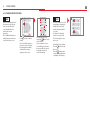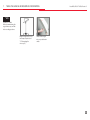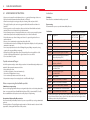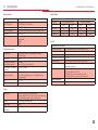
1
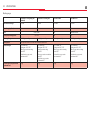
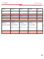
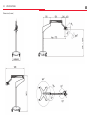
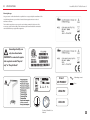
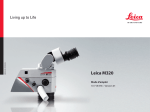
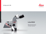
Medic al Division Leica M320 User Manual 10 718 878 - Version 01 Thank you for deciding in favor of a Leica surgical microscope system. For valuable information about Leica Microsystems products and services and the address of your nearest Leica representative, please visit our website: www.leica-microsystems.com Leica Microsystems (Schweiz) AG Medical Division Max Schmidheiny-Strasse 201 CH-9435 Heerbrugg Phone: +41 71 726 3333 Fax: +41 71 726 3334 Product identification The model code and serial number of your product are provided on the nameplate found on the underside of the control unit. Copy this information to the line below so that it is handy in case you have questions for our representatives or service locations. Type:Serial number: Contents Leica M320 / Ref. 10 718 878 / Version 01 1Introduction . . . . . . . . . . . . . . . . . . . . . . . . . . . . . . . . . . . . . . . . . . . . . . . . . . . . . . . . . . . . . . . . . . . 1 1.1Basics. . . . . . . . . . . . . . . . . . . . . . . . . . . . . . . . . . . . . . . . . . . . . . . . . . . . . . . . . . . . . . . . . . . . . . . . 1 4.12Installing the drape. . . . . . . . . . . . . . . . . . . . . . . . . . . . . . . . . . . . . . . . . . . . . . . . . . . . . . . . . 15 1.2Intended use. . . . . . . . . . . . . . . . . . . . . . . . . . . . . . . . . . . . . . . . . . . . . . . . . . . . . . . . . . . . . . . . . 1 4.13External orange filter. . . . . . . . . . . . . . . . . . . . . . . . . . . . . . . . . . . . . . . . . . . . . . . . . . . . . . . 16 1.3 Symbols. . . . . . . . . . . . . . . . . . . . . . . . . . . . . . . . . . . . . . . . . . . . . . . . . . . . . . . . . . . . . . . . . . . . . . 1 5Settings. . . . . . . . . . . . . . . . . . . . . . . . . . . . . . . . . . . . . . . . . . . . . . . . . . . . . . . . . . . . . . . . . . . . . . . . 17 1.4 Required tools. . . . . . . . . . . . . . . . . . . . . . . . . . . . . . . . . . . . . . . . . . . . . . . . . . . . . . . . . . . . . . . . 1 5.1 Balancing the swing arm. . . . . . . . . . . . . . . . . . . . . . . . . . . . . . . . . . . . . . . . . . . . . . . . . . . . 17 2instructions. . . . . . . . . . . . . . . . . . . . . . . . . . . . . . . . . . . . . . . . . . . . . . . . . . . . . . . . . . . . . . . . . . . . 2 5.2 Transporting the microscope . . . . . . . . . . . . . . . . . . . . . . . . . . . . . . . . . . . . . . . . . . . . . . . 18 2.1User profiles. . . . . . . . . . . . . . . . . . . . . . . . . . . . . . . . . . . . . . . . . . . . . . . . . . . . . . . . . . . . . . . . . . 2 5.3Starting up. . . . . . . . . . . . . . . . . . . . . . . . . . . . . . . . . . . . . . . . . . . . . . . . . . . . . . . . . . . . . . . . . 20 2.2Safety notes. . . . . . . . . . . . . . . . . . . . . . . . . . . . . . . . . . . . . . . . . . . . . . . . . . . . . . . . . . . . . . . . . . 2 5.4Additional settings . . . . . . . . . . . . . . . . . . . . . . . . . . . . . . . . . . . . . . . . . . . . . . . . . . . . . . . . . 22 2.3Directions for the operator of the instrument. . . . . . . . . . . . . . . . . . . . . . . . . . . . . . . . . . 3 6Video Camera. . . . . . . . . . . . . . . . . . . . . . . . . . . . . . . . . . . . . . . . . . . . . . . . . . . . . . . . . . . . . . . . . . 28 2.4Disposal. . . . . . . . . . . . . . . . . . . . . . . . . . . . . . . . . . . . . . . . . . . . . . . . . . . . . . . . . . . . . . . . . . . . . . 3 6.1Information . . . . . . . . . . . . . . . . . . . . . . . . . . . . . . . . . . . . . . . . . . . . . . . . . . . . . . . . . . . . . . . . 28 3Controls . . . . . . . . . . . . . . . . . . . . . . . . . . . . . . . . . . . . . . . . . . . . . . . . . . . . . . . . . . . . . . . . . . . . . . . . 4 6.2SD memory card. . . . . . . . . . . . . . . . . . . . . . . . . . . . . . . . . . . . . . . . . . . . . . . . . . . . . . . . . . . . 29 3.1Stands. . . . . . . . . . . . . . . . . . . . . . . . . . . . . . . . . . . . . . . . . . . . . . . . . . . . . . . . . . . . . . . . . . . . . . . 4 6.3 Remote control. . . . . . . . . . . . . . . . . . . . . . . . . . . . . . . . . . . . . . . . . . . . . . . . . . . . . . . . . . . . . 29 3.2Swing arm and horizontal arm. . . . . . . . . . . . . . . . . . . . . . . . . . . . . . . . . . . . . . . . . . . . . . . . 5 6.4 Graphical user interface. . . . . . . . . . . . . . . . . . . . . . . . . . . . . . . . . . . . . . . . . . . . . . . . . . . . . 30 3.3Optics carrier. . . . . . . . . . . . . . . . . . . . . . . . . . . . . . . . . . . . . . . . . . . . . . . . . . . . . . . . . . . . . . . . . 6 6.5Acquisition. . . . . . . . . . . . . . . . . . . . . . . . . . . . . . . . . . . . . . . . . . . . . . . . . . . . . . . . . . . . . . . . . 44 3.4 Microscope carrier. . . . . . . . . . . . . . . . . . . . . . . . . . . . . . . . . . . . . . . . . . . . . . . . . . . . . . . . . . . . 6 7 Taking the Surgical Microscope out of Operation. . . . . . . . . . . . . . . . . . . . . . . 49 3.5 Brake knobs/articulation brakes. . . . . . . . . . . . . . . . . . . . . . . . . . . . . . . . . . . . . . . . . . . . . . . 7 3.6Connections. . . . . . . . . . . . . . . . . . . . . . . . . . . . . . . . . . . . . . . . . . . . . . . . . . . . . . . . . . . . . . . . . . 8 8Care and Maintenance. . . . . . . . . . . . . . . . . . . . . . . . . . . . . . . . . . . . . . . . . . . . . . . . . . . . . . . 50 8.1 Maintenance instructions. . . . . . . . . . . . . . . . . . . . . . . . . . . . . . . . . . . . . . . . . . . . . . . . . . . 50 4Accessories. . . . . . . . . . . . . . . . . . . . . . . . . . . . . . . . . . . . . . . . . . . . . . . . . . . . . . . . . . . . . . . . . . . . . . 9 8.2Changing fuses. . . . . . . . . . . . . . . . . . . . . . . . . . . . . . . . . . . . . . . . . . . . . . . . . . . . . . . . . . . . . 51 4.1Installing the accessories . . . . . . . . . . . . . . . . . . . . . . . . . . . . . . . . . . . . . . . . . . . . . . . . . . . . . 9 4.2Documentation output. . . . . . . . . . . . . . . . . . . . . . . . . . . . . . . . . . . . . . . . . . . . . . . . . . . . . . . 9 4.3Handles. . . . . . . . . . . . . . . . . . . . . . . . . . . . . . . . . . . . . . . . . . . . . . . . . . . . . . . . . . . . . . . . . . . . 10 4.4ErgonOptic Dent . . . . . . . . . . . . . . . . . . . . . . . . . . . . . . . . . . . . . . . . . . . . . . . . . . . . . . . . . . . . 11 4.5ErgoWedge. . . . . . . . . . . . . . . . . . . . . . . . . . . . . . . . . . . . . . . . . . . . . . . . . . . . . . . . . . . . . . . . . . 11 4.6Objectives. . . . . . . . . . . . . . . . . . . . . . . . . . . . . . . . . . . . . . . . . . . . . . . . . . . . . . . . . . . . . . . . . . 12 4.7 Protective glass. . . . . . . . . . . . . . . . . . . . . . . . . . . . . . . . . . . . . . . . . . . . . . . . . . . . . . . . . . . . . 12 4.8 Binocular tubes. . . . . . . . . . . . . . . . . . . . . . . . . . . . . . . . . . . . . . . . . . . . . . . . . . . . . . . . . . . . . 13 4.9Eyepieces . . . . . . . . . . . . . . . . . . . . . . . . . . . . . . . . . . . . . . . . . . . . . . . . . . . . . . . . . . . . . . . . . . 13 4.10Adapter. . . . . . . . . . . . . . . . . . . . . . . . . . . . . . . . . . . . . . . . . . . . . . . . . . . . . . . . . . . . . . . . . . . . 14 4.11 Mounting sterile components . . . . . . . . . . . . . . . . . . . . . . . . . . . . . . . . . . . . . . . . . . . . . . 15 9Troubleshooting. . . . . . . . . . . . . . . . . . . . . . . . . . . . . . . . . . . . . . . . . . . . . . . . . . . . . . . . . . . . . 52 9.1Microscope. . . . . . . . . . . . . . . . . . . . . . . . . . . . . . . . . . . . . . . . . . . . . . . . . . . . . . . . . . . . . . . . . 52 9.2Video camera . . . . . . . . . . . . . . . . . . . . . . . . . . . . . . . . . . . . . . . . . . . . . . . . . . . . . . . . . . . . . . 52 10Specifications. . . . . . . . . . . . . . . . . . . . . . . . . . . . . . . . . . . . . . . . . . . . . . . . . . . . . . . . . . . . . . . . . 61 1Introduction Leica M320 / Ref. 10 718 878 / Version 01 1.1Basics 1.3Symbols Be sure to read the User Manual and the "Safety Notes" chapter carefully before assembling and operating the product. 1.3.1 In the manual Keep the manual close to the instrument. 1.2Intended use The Leica surgical microscope is an optical instrument for magnifying and illuminating specimens. It can be applied for observation and documentation and for human and veterinary medical treatment. The Leica surgical microscope may be used only in closed rooms and must be placed on a solid floor or attached to a strong wall or ceiling. Not for use in eye operations! The Leica M320 surgical microscope is subject to special precautionary measures for electromagnetic compatibility. It must be installed and commissioned in accordance with the guidelines and manufacturer's declarations and recommended safety distances (tables 1, 2, 4, 6 a ccording to EN 60601-1: 2007). Portable and mobile as well as stationary HF communications equipment can have a negative effect on the reliability of the Leica M320 surgical microscope. Warning Can cause death or severe injury. CAUTION Can cause minor injury. NOTE Can cause property damage. INFO Information that is not safety-related, but is useful or important. 1.3.2 On the instrument Caution, follow the User Manual Alternating current European Conformity logo 1.4 Required tools Allen key: -- Size 2.5 for installing accessories (dovetail interface) -- Size 3 for optimizing the balance of the optics carrier -- Size 4 for handle holder -- Size 8 for balancing the swing arm Provided brake knob 1 2Instructions 2 2.1User profiles 2.2Safety notes Responsible body Person or company responsible for the use and maintenance of the surgical microscope (hospitals, physician's practices). Information for the person responsible for the instrument/authorized trained personnel Users Physicians and trained medical personnel with appropriate qualifications who have been instructed in the use of the instrument. Specific training is not required. Authorized trained personnel Authorized electricians or other technicians expressly authorized by Leica with corresponding training. -- The surgical microscope may be used by qualified users only. -- Regularly check to make sure the users are complying with safety requirements. -- Provide comprehensive instructions and explain the warning messages. -- Assign and monitor responsibilities for commissioning, operating and maintenance. -- Use the surgical microscope in proper condition only. -- Do not place the drape to close to the instrument, as otherwise it can overheat and shut off. -- Inform your Leica representative or Leica Microsystems (Schweiz) AG immediately if you detect a product defect that could potentially cause injury or harm. -- Use original accessories or approved Leica accessories only. -- Use only high-quality HDMI cables with a maximum length of 15 m. -- Use only monitors approved for medical purposes or equipped with an isolating transformer. -- Modifications or repairs may be carried out by authorized trained personnel only. -- Use only original Leica parts in maintenance work. -- After maintenance or technical modifications, readjust the instrument in accordance with our technical specifications. -- If the instrument is modified by or maintenance has been performed by unauthorized personnel, if the equipment is improperly maintained or if the instrument has been operated improperly, Leica disclaims all liability. -- The owner or operator shall be held liable for the function of the system if the system has been assembled incorrectly by individuals who do not belong to Leica Microsystems (Schweiz) AG. -- The influence on other devices by the Leica M320 surgical microscope has been tested in accordance with EN 60601-1-2. The system passed the emissions and immunity test. The standard preventive measures and safety regulations pertaining to electromagnetic and other radiation have to be observed. 2Instructions Leica M320 / Ref. 10 718 878 / Version 01 2.3Directions for the operator of the instrument -- Follow the User Manual. -- Follow the instructions given by your employer regarding the organization of work and safety at work. -- Do not modify the surgical microscope. -- Danger of tilting of the floor stand! When moving the floor stand, fold up the swing arm as described above and tighten the articulation brakes. -- Risk of injury from moving parts! Assemble and balance the accessories before the operation. Do not install it above the field of operation. -- Risk of injury from rolling of the floor stand! Always push the microscope to move it; never pull it. Do not roll it over anyone's feet. Do not roll over cables lying on the floor. Lock the foot brakes during the operation, and never move the device during operation. -- Do not shine lights in anyone's eyes. -- Do not cover up the ventilation slot of the optics carrier. -- Before an extended period of non-use, remove the battery from the remote control. 2.4Disposal The respective applicable national laws must be observed for disposal of the products, with the involvement of corresponding disposal companies. The unit packaging is to be recycled. 3 3Controls 4 3.1Stands NOTE To assemble the stand, note the installation instructions provided. Rolling floor stand (F12), long swing arm Rolling floor stand, short swing arm Wall stand (W12) Ceiling mount (C12) Table stand with terminal (TC12) Wall stand (LW12) Table stand with plate (TP12) Standard for operating manual Floor stand/baseplate (FP12) 3Controls Leica M320 / Ref. 10 718 878 / Version 01 3.2Swing arm and horizontal arm Integrated tilt switch INFO The integrated tilt switch is not available for models TC12, TP12 and LW12. Swing arm and horizontal arm Move the swing arm upwards. Light switches off automatically. 5 3Controls 6 3.3Optics carrier INFO Caps for magnification changer are steam- or gas-sterilizable. Magnification changer, both sides, increments: 6.4, 10, 16, 25, 40× Illumination control for illumination intensity. Filter and diaphragm controls for white light, orange filter and spot illumination. 3.4 Microscope carrier INFO INFO Two different versions are available. Upright installation is not possible for models TC12, TP12 and LW12. Inclined Upright Types of counterweight for balancing when many accessories are used. 3Controls Leica M320 / Ref. 10 718 878 / Version 01 3.5 Brake knobs/Articulation brakes Articulation brake Lever for locking the vertical position Joint for balancing Articulation brake Articulation brake Articulation brake (LW12, TP12, TC12) Tilt brake Rotary brake (inclined version) 7 3Controls 8 3.6Connections Brake knob for setting the articulation brakes Main switch Power socket Port for HDMI/USB cable 4Accessories Leica M320 / Ref. 10 718 878 / Version 01 4.1Installing the accessories CAUTION Risk of injury from downward movement of the swing arm! Before installing accessories, tighten the articulation brakes. See "5.3 TRANSPORTING THE MICROSCOPE". INFO 1 2 3 Installing the accessories, for example, ErgonOptic Dent. Install any other accessories in a similar manner. Unscrew the clamping screw. Push the accessory into the dovetail interface. Tighten the clamping screw. 4.2Documentation output C-mount port for commercially available video camera 9 4Accessories 10 4.3Handles 4.3.1 Installing and removing the front handle NOTE Installing the front handle before the rest of the accessories. INFO 1 2 3 Gray handle sleeves are steam- or gas-sterilizable. White handle sleeves can be disinfected. Screw on the handle sleeve holder. Insert until the handle sleeve clicks into place. Push the knob and release the handle sleeve. 4.3.2 Installing the side handles 1 Screw the handle apart. 2 Remove cover with key. 3 Screw open the bottom holder for the handle. Handle tilt is individually adjustable. 4 Refit the handle sleeve holder. 5 Insert until the handle sleeve clicks into place. 4Accessories Leica M320 / Ref. 10 718 878 / Version 01 4.4ERGONOPTIC DENT INFO Improves ergonomics at certain working positions: Turning range 45° with 180° binocular tube. ErgonOptic Dent: Optical extension for more comfortable work. For installation, see "4.1 Installing the accessories". ErgoWedge Ideal in combination with 45° inclined binocular tube. 4.5Ergowedge INFO The ErgoWedge gives a binocular with a fixed angle a variable viewing angle of 5° to 25°. For installation, see "4.1 Installing the accessories". 11 4Accessories 12 4.6Objectives INFO 1 2 3 Fixed and fine objectives available in various focal lengths. Remove the cover from the optics carrier. Screw in the objective. Fine focusing objective: The nose points forward. Fixed objective: The nose points 90° towards the left or right. 4.7 Protective glass INFO The protective glass is used to protect the objective. The glass is steam- or gassterilizable. Turn the fine focusing objective for fine focus. 4Accessories Leica M320 / Ref. 10 718 878 / Version 01 4.8 Binocular tubes Binocular tube 5° - 25° Inclined binocular tube Binocular tube, 180° variable Straight binocular tube Binocular tube, variable 30° - 150° 4.9Eyepieces INFO Inclined binocular tube 45° For installation, see "4.1 Installing the accessories". Possible eyepieces: -- 10× eyepiece, standard (aside from with straight tube 12.5×) -- 10× eyepiece with crosshair graticule for easier image centering -- 12.5× eyepiece, shows image with similar magnification to that on the screen 1 Set the eyepiece in place. 2 Tighten the rotary ring. 13 4Accessories 14 4.10Adapter NOTE 1 3 2 4 The microscope is not balanced. To prevent it from tipping over, tighten the articulation brakes. Install the stereo adapter. 5 Fit the beam splitter. For 50/50 % or 70/30 % observation. NOTE For installation, see "4.1 Installing the accessories". Turn the white ring to align the cutout for the assistant. Install the stereo attachment for second observer on the left side. Fit the binocular tubes. 4Accessories Leica M320 / Ref. 10 718 878 / Version 01 4.11 Mounting sterile components CAUTION INFO Danger of infection! Avoid touching the sterile components. Allow sufficient free space. 1 2 3 Do not install the sterile components until shortly before the operation. Handle sleeves and caps for the magnification changer are steam and gas-sterilizable. Sterilize the handle sleeves and caps after use. Insert until the handle sleeve clicks into place. Attach the caps. Attach protective glass on objective. The noise points forwards (fine focus objectives) or 90° to the left/ right (fixed objectives). 4.12Installing the drape CAUTION cm 20 Do not wrap the drape around the microscope too tightly. The distance between the microscope and drape should be 20 cm. Danger of overheating! Fit the drape. 15 4Accessories 16 4.13External orange filter NOTE INFO Filters out the parts of the light spectrum that cause rapid curing of dental composite. For installation, refer to the separate Assembly Instructions provided. External orange filter: additional accessory for dentistry. 5Settings 5.1 Leica M320 / Ref. 10 718 878 / Version 01 Balancing the swing arm 1 Remove the screw. 6 Refit the side cover. 2 Remove the side cover. 7 Fasten the screw. 3 Remove the screws. 8 Turn the lever for locking the vertical position. 4 Set the desired position. Four different positions can be set. 5 Fasten the screws. 9 Adjust the balancing joint to the weight using an Allen key (size 8). 17 5Settings 18 5.2 Transporting the microscope CAUTION 1 2 3 4 Risk of injury from outward movement of swinging arm! Transport the microscope in transport position. Place swing arm in a horizontal position. 5 Open the articulation brake. 6 Fold the swing arm together. Tighten the articulation brake. Turn the lever for locking the vertical position. 7 Compare the position of the swing arm with the attached sign. Turn the optics/microscope carrier towards the outside. Tighten the articulation brake. 5Settings NOTE Leica M320 / Ref. 10 718 878 / Version 01 8 9 Possible damage of the cable! Always pull the plug, never the cable. 10 Risk of injury to feet! Always push the instrument to move it; never pull it. Unplug the power cable. CAUTION CAUTION Release the foot brakes. Push the microscope to the installation location and position it. 11 Danger of microscope rolling away on its own! Tighten the foot brakes. Tighten the foot brakes. 19 5Settings 20 5.3STARTING UP Warning Risk of death from electrical shock! Connect the microscope to a grounded socket only. INFO The length of the HDMI cable must not exceed 15 m. Use only high-quality HDMI cables. HDMI cables are available from Leica. 1 Remove cover of the horizontal arm. 2 Plug the power cable into the horizontal arm and fasten it using cable ties. INFO Image output: Resolution is always in HD format (720p/1080i/1080p). Check to ensure that the monitor is compatible with the HD standard. 3 Plug the HDMI cable and USB cable (optional) into the horizontal arm and fasten it using cable ties. INFO Use only monitors approved for medical purposes or equipped with an isolating transformer. Isolating transformers are available from Leica. 4 Screw in the cover of the horizontal arm and tighten it. 5 Connect the HDMI cable to a suitable monitor or screen. 5Settings 6 Connect the USB cable to the computer. Leica M320 / Ref. 10 718 878 / Version 01 7 Connect the power cable. 8 Switch on the main switch. Main switch lights up in green. 9 White LED illumination on the optics carrier lights up. 21 5Settings 22 5.4Additional settings 5.4.1ADJUSTING THE DESIGN LED ILLUMINATOR INFO 1 2 3 4 There are five different dimming levels. Switch on the main switch. Main switch lights up in green. 5.4.2Adjusting the working distance 1 Coarse focus by raising and lowering the microscope. 2 Fine focus via optional fine focusing objective. Remove cover of the horizontal arm. Using a ball-point pen or similar object, press the switch until the desired dimming level is reached. Screw in the cover of the horizontal arm and tighten it. 5Settings Leica M320 / Ref. 10 718 878 / Version 01 5.4.3Adjusting the illumination Warning 1 2 Danger of retinal damage! Do not shine lights in anyone's eyes. Set the desired illuminance. Select the desired filter or diaphragm function: White light Orange filter Spot illumination 5.4.4Adjusting the interpupillary distance 1 Look into the eyepieces. Depending on the model, move the tube manually or using the drive knob until a circular field is visible. 23 5Settings 24 5.4.5Adjusting the parfocality with camera and monitor INFO 1 2 3 Parfocal means that the sharpness remains constant over the entire magnification range. Adjust the diopter settings for both eyes separately and accurately. Place a piece of paper with writing on it under the objective. Maximum magnification (40×) Bring the writing on the sheet of paper into sharp focus on the monitor. Adjusting the diopter settings 4 Without looking into the eyepieces, set the minimum magnification (6.4×). The image on the monitor must remain sharp! 5 Turn the dioptric correction on the eyepieces to "+5". 6 Look into the eyepieces. Rotate each eyepiece individually clockwise, in the "–5" direction, until each eye sees the writing in sharp focus. 7 Set maximum magnification (40×). 5Settings 8 Leica M320 / Ref. 10 718 878 / Version 01 9 INFO The writing should now remain sharp when you change the magnification. If it does not, repeat the procedure. Bring the writing on the sheet into focus. Turn out the eyecups to the desired distance. 25 5Settings 26 5.4.6Adjusting the parfocality without camera and monitor Personal diopter setting known: INFO 1 Parfocal means that the sharpness remains constant over the entire magnification range. Adjust the diopter settings for both eyes separately and accurately. Set dioptric correction on eyepieces. Personal diopter setting known: 1 Adjust the dioptric setting at the eyepiece to 0. 2 Place a piece of paper with writing on it under the objective. 3 Set maximum magnification (40×) 4 Bring the writing on the sheet of paper into focus. 5Settings 5 Without looking into the eyepieces, set the minimum magnification (6.4×). Leica M320 / Ref. 10 718 878 / Version 01 6 Turn the dioptric correction on the eyepieces to "+5". 7 Look into the eyepieces. Rotate each eyepiece individually clockwise, in the "–5" direction, until each eye sees the writing in sharp focus. 8 Set maximum magnification (40×). 9 Turn out the eyecups to the desired distance. INFO The writing should now remain sharp when you change the magnification. If it does not, repeat the procedure. 27 6Video Camera 28 6.1Information 6.1.1Standard delivery -- Remote control -- SD card (8 GB or similar) Optional accessories: -- USB (A-B) cable, 1.8 m -- USB with Repeater cable, 10 m 6.1.2Requirements -- HDMI port: HDMI-capable screen or television set to the HD ready (720 p) or Full-HD (1080 p) standard. and/or -- USB port: Computer with USB connector 6.1.3Effective displayed section INFO The live image and captured image do not show the same section one sees when looking through eyepieces. To simplify image centering, install 10.5× eyepiece with crosshair graticule. 10× eyepiece 12.5× eyepiece 4:3 aspect ratio 16:9 aspect ratio 4:3 section 16:9 section 6Video Camera Leica M320 / Ref. 10 718 878 / Version 01 6.2SD Memory card 1 INFO An SD memory card cannot be formatted in the video camera. Format it at a computer or external digital camera. The video camera is designed for SD memory cards up to 32 GB. Leica recommends SD memory cards from Kingston or SanDisc (Speed Class 4 or better). Push down the cover flap. 2 Insert the SD memory card into the video camera. 3 Push in the SD memory card and remove it. 6.3 Remote control 6.3.1Changing the battery Changing the battery 1 Remove the battery insert from the rear side. 2 Replace the battery. (Button battery type CR2032) 29 6Video Camera 30 6.3.2Overview 1 Perform white balance adjustment 2Save still image to SD Card 1 7 2 8 3 9 4 10 11 5 5 6 10 3 Thumbnail mode / live view mode 4 Perform remote control pairing 5Arrow keys for navigation 6Enter / exit Camera Menu 7Start / stop video recording 8 Freeze live view / pause video 9Show / hide information menu 10Arrow keys for navigation 11OK / confirm 6.4 Graphical user interface 6.4.1Camera menu 1 Point the remote control towards the camera.. 2 Call up the Camera Menu button. with 3 Navigate with arrow keys. 4 Press to confirm. 6Video Camera Leica M320 / Ref. 10 718 878 / Version 01 6.4.2Color (white balance) INFO Use neutral white or gray color chart for manual white balance adjustment. Manual White Balance (recommended) Manual white balance can be set by: 1. Lay a neutral white paper or gray chart under the focus of the microscope. Press WB on the remote control. COLOR SET WB PRESS OK EXPOSURE WB MODE MANUAL RESOLUTION RED LEVEL 039 SETUP CAMERA BLUE LEVEL 039 SETUP USER BLACK LEVEL 000 2. Lay a neutral white paper or gray chart under the focus of the microscope. Select . Adjust ‘RED LEVEL’, ‘BLUE LEVEL’, and ‘BLACK LEVEL’ as needed. “Set WB” and press SET FILENAME SET WB PRESS OK WB MODE MANUAL RED LEVEL 039 BLUE LEVEL 039 BLACK LEVEL 000 3. Select “MANUAL” under WB mode. Adjust ‘RED LEVEL’, ‘BLUE LEVEL’, and ‘BLACK LEVEL’ as needed. Automatic White Balance Color Set WB Exposure WB Mode Resolution Red level 039 Setup Camera Blue level 039 Setup User Black level 000 SET FILENAME Press OK Auto Select “AUTO” for automatic white balance adjustment. White balance is adjusted automatically in real-time. Adjust the “BLACK LEVEL” as needed. 31 6Video Camera 32 6.4.3EXPOSURE Manual exposure Color EXP Mode Manual Exposure EXPOSURE 067 Resolution GAIN 067 Setup Camera BRIGHTNESS 077 Setup User GAMMA Set FILENAME ALC Select "MANUAL" for manual exposure. Correct the values for "EXPOSURE", "GAIN", and "GAMMA". 0.40 NO MASK Automatic exposure (Recommended) Color EXP Mode Exposure EXPOSURE 067 Resolution GAIN 067 Setup Camera BRIGHTNESS 077 Setup User GAMMA SET FILENAME ALC Auto Select "AUTO" for automatic exposure. Correct the values for "BRIGHTNESS" and "GAMMA". 0.40 NO MASK Automatic Light Control (ALC) Color EXP Mode Exposure EXPOSURE 067 Resolution GAIN 067 Setup Camera BRIGHTNESS 077 Setup User GAMMA SET FILENAME ALC Auto 1.40 NO MASK For automatic exposure, 5 types of “ALC” can be selected: “NO MASK”, “GRID”, “S CIRCLE”, “M CIRCLE” and “L CIRCLE” 6Video Camera Leica M320 / Ref. 10 718 878 / Version 01 INFO No Mask The exposure is automatically adjusted based on the entire image seen on the screen. Grid The exposure is automatically adjusted based on the grid(s) selected. S Circle The exposure is automatically adjusted based on the small sized circle (“S CIRCLE”), as indicated on the screen. M Circle The exposure is automatically adjusted based on the medium sized circle (“M CIRCLE”), as indicated on the screen. L Circle The exposure is automatically adjusted based on the large sized circle (“L CIRCLE”), as indicated on the screen. 33 6Video Camera 34 6.4.4RESOLUTION LIVE Color LIVE HD 1080-25 Exposure CAPTURED 10.0MP-JPG Resolution MOVIE HD 1080-MP4 Setup Camera Select the resolution for live view: (16×9 mode) HD720p50, HD720p60, HD1080p25, HD1080p30, HD1080i50, HD1080i60. (4×3 mode) 720p50-4×3,720p60-4×3,1080i50-4×3,1080i60-4×3. Setup User SET FILENAME CAPTURED Color LIVE Exposure CAPTURED Resolution MOVIE HD 1080-MP4 Color LIVE HD 1080-25 Exposure CAPTURED 10.0MP-JPG Resolution MOVIE HD 1080-MP4 HD 1080-25 10.0MP-JPG Select resolution for still image: 2.5 MP, 5.0 MP,10.0 MP. Setup Camera Setup User SET FILENAME MOVIE Setup Camera Setup User SET FILENAME Select resolution for video file: HD1080, HD720. 6Video Camera INFO If a resolution cannot be displayed and the HD monitor remains black, you can do the following to display a live image again in the HD monitor: Leica M320 / Ref. 10 718 878 / Version 01 Use the tip of a ball-point pen (or a bent paperclip) to press the hidden button: Pressing the button for the first time displays the current live image resolution on the HD monitor. Pressing it a second time switches to the next live image resolution and a signal tone is output. Repeat the last step until a live image is displayed. The camera can activate 10 different resolutions in sequence. 35 6Video Camera 36 6.4.5SETUP CAMERA (VIDEO CAMERA SETTINGS) CAPTURE MODE Color CAPTURE MODE NORMAL Exposure set DATE/TIME Press ok Resolution SHOW DATE/TIME none Setup Camera SHOW FILENAME NONE Setup User FLIP IMAGE 0° SET FILENAME AUDIO/BEEP ON LEICA LOGO NONE RESET CAM Press ok Color CAPTURE MODE NORMAL Exposure set DATE/TIME Press ok Resolution SHOW DATE/TIME none Setup Camera SHOW FILENAME NONE Setup User FLIP IMAGE 0° SET FILENAME AUDIO/BEEP ON LEICA LOGO NONE RESET CAM Press ok Select the still image capture mode: Normal:Normal capture mode (Recommended) High Sens: High sensitivity mode. This option helps to capture sharper image when the object is moving Burst: 3 images will be captured consecutively SET DATE/TIME Set the date/time and select the format: “DMY” =Day/Month/Year, 24 h “MDY” = Month/Day/Year, 12 h (AM/PM) “YMD” =Year/Month/Day, 24 h 6Video Camera Leica M320 / Ref. 10 718 878 / Version 01 SHOW DATE/TIME Color CAPTURE MODE NORMAL Exposure set DATE/TIME Press ok Resolution SHOW DATE/TIME none Setup Camera SHOW FILENAME NONE Setup User FLIP IMAGE 0° SET FILENAME AUDIO/BEEP ON LEICA LOGO NONE RESET CAM Press ok Color CAPTURE MODE NORMAL Exposure set DATE/TIME Press ok Resolution SHOW DATE/TIME none Setup Camera SHOW FILENAME NONE Setup User FLIP IMAGE 0° SET FILENAME AUDIO/BEEP ON LEICA LOGO NONE RESET CAM Press ok Select the option for Show Date/Time: LIVE ONLY:Date/Time in live view only IMG ONLY:Date/Time in still captures only LIVE + IMG:Date/Time in live view + still captures SHOW FILENAME Select the option for Show Filename: LIVE ONLY: Filename in live view only IMG ONLY: Filename in still captures only LIVE + IMG: Filename in live view + still captures 37 6Video Camera 38 FLIP IMAGE Color CAPTURE MODE NORMAL Exposure set DATE/TIME Press ok Resolution SHOW DATE/TIME none Setup Camera SHOW FILENAME NONE Setup User FLIP IMAGE 0° SET FILENAME AUDIO/BEEP ON LEICA LOGO NONE RESET CAM Press ok Select the option for the image orientation: 0° Original orientation Image is mirrored horizontally Image is mirrored vertically 180° Image is rotated 180° AUDIO/BEEP Color CAPTURE MODE NORMAL Exposure set DATE/TIME Press ok Resolution SHOW DATE/TIME none Setup Camera SHOW FILENAME NONE Setup User FLIP IMAGE 0° SET FILENAME AUDIO/BEEP ON LEICA LOGO NONE RESET CAM Press ok Select “ON” to have audio signal when capturing still images or initiating video recordings. 6Video Camera Leica M320 / Ref. 10 718 878 / Version 01 LEICA LOGO Color CAPTURE MODE NORMAL Exposure set DATE/TIME Press ok Resolution SHOW DATE/TIME none Setup Camera SHOW FILENAME NONE Setup User FLIP IMAGE 0° SET FILENAME AUDIO/BEEP ON LEICA LOGO NONE RESET CAM Press ok Color CAPTURE MODE NORMAL Exposure set DATE/TIME Press ok Resolution SHOW DATE/TIME none Setup Camera SHOW FILENAME NONE Setup User FLIP IMAGE 0° SET FILENAME AUDIO/BEEP ON LEICA LOGO NONE RESET CAM Press ok Select the option for Leica Logo: 1. NONE :No Logo display 2. LIVE ONLY :Logo in live view only 3. IMG ONLY :Logo in still captures only 4. LIVE + IMG:Logo in live view + still captures RESET CAMERA Press to restore all settings of the video camera to the factory settings. 39 6Video Camera 40 6.4.6SETUP USER (USER-DEFINED SETTINGS) MENUE COLOR Color Menu color DEFAULT Exposure Show capture Resolution Show menu Setup camera LANGUAGE ENGLISH Color Menu color DEFAULT Exposure Show capture Resolution Show menu Setup camera LANGUAGE ENGLISH Color Menu color DEFAULT Exposure Show capture Resolution Show menu Setup camera LANGUAGE OFF Select color scheme for menu: “LEICA/LAS “ : red “DEFAULT” :blue 05 sec Setup user SET FILENAME SHOW CAPTURE OFF 05 sec Select the display mode & display duration of the image after it is captured: “OFF”, “FULL-1SEC”, “PIP-1SEC”, “FULL-3SEC”, “PIP-3SEC”, “PIP-INFI”. FULL: : Full screen PIP: : Picture in picture Setup user SET FILENAME SHOW MENUE Setup user SET FILENAME OFF 15 sec ENGLISH Select the display duration of the Camera Menu on the screen: “5 SEC “, “10 SEC “, “15 SEC “, “20 SEC “, “25 SEC “, “30 SEC “ 6Video Camera Leica M320 / Ref. 10 718 878 / Version 01 LANGUAGE Color Menu color Exposure Show capture Resolution Show menu Setup camera LANGUAGE DEFAULT OFF 05 sec ENGLISH Select the language. Setup user SET FILENAME 6.4.7SET FILENAME Color Exposure M 320 Set the first 4 characters of the filenames for still captures and the video recordings. Resolution Setup camera Setup user SET FILENAME INFO All the files will be saved in one folder, where the name of the folder is be generate based on the file name set. For example:Set Filename = M320 Filename = M32000001.JPG. Folder name = 100M320_ 41 6Video Camera 42 6.4.8QUICK MENU FILE TRANSFER MODE 1 QUICK MENU FILE TRANSFER Press to call up the “QUICK MENU”. Select “FILE TRANSFER MODE”, and press . INFO In “FILE TRANSFER MODE”, the SD card will appear as ‘Removable Disk’ on the PC, and files can be copied from the SD card and pasted to the local PC. SET FILENAME 1 QUICK MENU SET FILENAME Select “SET FILENAME” to enter “SET FILENAME” menu. QUICK MENU LENS SHADING Select “LENS SHADING” and press . Select the lens shading setting based on the actual magnification used: 6.4×, 10.0×, 16.0×, 25.0×, 40.0×. LENS SHADING 1 6Video Camera Leica M320 / Ref. 10 718 878 / Version 01 6.4.9AUTOMATIC LIGHT CONTROL (ALC) 1 ALC NO MASK Press to select the ALC mode: “NO MASK”, “GRID”, “S CIRCLE”, “M CIRCLE”, OR “L CIRCLE” CAPTURE MODE NORMAL Press to select the capture mode: “NORMAL”, “HIGH SENS” or “BURST” 6.4.10CAPTURE MODE 1 43 6Video Camera 44 6.5Acquisition 6.5.1Images 1 Press on the remote control or on the video camera still images. A signal tone sounds. 2 3 4 2. Entering “FILE TRANSFER MODE” and the SD card will appear as “Removable Disk” on the computer. Files can be transferred to PC by: 1. Removing the SD card from the camera and insert the SD card into the SD card reader on the computer. 6.5.2Videos 1 Press on the remote control or on the video camera to initiate video recordings. A signal tone sounds. To end the video recording, press on the remote control or on the video camera. A signal tone sounds. 2 Files can be transferred to PC by: 1. Removing the SD card from the camera and insert the SD card into the SD card reader on the computer. 3 Transfer the video to a computer using the SD card reader. 6Video Camera Leica M320 / Ref. 10 718 878 / Version 01 4 INFO You can show and hide the timer using the key. 2. Entering “FILE TRANSFER MODE” and the SD card will appear as “Removable Disk” on the computer. 6.5.3Viewing images 1 Press mode. 2 to enter thumbnail Navigate by using the arrow keys. Press to select the image. 3 4 Image selected will be displayed in full screen. 45 6Video Camera 46 ROTATING IMAGE 1 To rotate the image, press to enter the rotation menu. 2 3 Press to rotate the image counter clockwise. Press to rotate the image clockwise. Press view. Press to enlarge the still image. (Zoom 2×) 2 to return to live ZOOMING IMAGE 1 Continue to press to enlarge the still image. (Zoom 3×, Zoom 4×) Press 4 times to return to original image size. Press to return to live view. 6Video Camera Leica M320 / Ref. 10 718 878 / Version 01 6.5.4Viewing videos 1 Press mode. 2 to enter thumbnail 3 Navigate by using the arrow keys. Press to play the video. 4 5 Press to forward the video. Press to rewind the video. Press to return to live view. Press to pause / resume the video. 6.5.5DELETING FILES 1 Press mode. 2 to enter thumbnail Navigate by using the arrow keys. Press to select the image for deletion. 3 4 Confirm the file name to be deleted. Select “OK” to permanently delete the file from SD card. Select “CANCEL” to cancel the file deletion process. 47 6Video Camera 48 6.5.6PAIRING REMOTE CONTROL INFO Remote control pairing allows the camera to only responds to the one specific remote control, which had been paired to the camera previously. This is helpful when there are multiple cameras and remote controls in the same room. 1 2 01 02 03 04 05 06 07 09 08 11 Press to start or end the pairing. Press and hold the button on the remote control, to define the pairing button, until the confirmation message is displayed on the screen. 10 12 All of the buttons (01–12) except the button can be used for this. Upon completion, a ‘beep’ sound will be generated and the camera will only respond to this particular remote control after pairing. INFO In order to achieve successful pairing and avoid pairing by mistake, the second step must be performed within 4 seconds. If a “timeout” is displayed after 4 seconds, press the “Pair” button again to start the process. Resetting to factory setting: Press the button to start the process. Press the button until a corresponding confirmation is displayed on the display. 3 7 Taking the Surgical Microscope out of Operation Leica M320 / Ref. 10 718 878 / Version 01 NOTE Possible loss of data! Before decommissioning the surgical microscope, end the video recording procedure. Bring the surgical microscope into transport position (see "5.3 Transporting the microscope"). Switch off the surgical microscope at the main switch. 49 8Care and Maintenance 50 8.1 Maintenance instructions Instructions -- Keep accessories away from dust when not in use, e.g. protect them using a dust cover. -- Remove dust with a pneumatic rubber bulb and a soft brush. -- Clean lenses and eyepieces using special optics cleaning cloths and pure alcohol. -- Thoroughly clean the optics carrier using germicidal disinfectant after each time it is handled. -- Protect your microscope from moisture, fumes and acids and from alkaline and caustic materials. Do not store chemicals close to the instrument. -- Protect from improper use. Never install other device sockets or unscrew optical systems and mechanical parts unless explicitly instructed to do so in this User Manual. -- Protect the microscope from oil and grease. Never oil or grease the guide surfaces or mechanical parts. -- Remove coarse contamination using a damp disposable cloth. -- Use disinfectants based on the following active ingredients: aldehydes, alcohols, quaternary ammonium compounds. -- No not use preparations based on the following: halogen-splitting compounds, strong organic acids, oxygen-splitting compounds. -- Camera: Keep optical components clean. Clean optical surfaces using a lint-free cloth. Soak the cloth using a little methanol or glass cleaner. Do not use alcohol. -- Do not use ethanol or spirits. Workplace Remove surface contamination with a paper towel. Tropical environment/fungus Leica Microsystems employs certain safety precautions in its manufacturing techniques and materials. Other preventive measures include: -- Keep optical parts clean. -- Use and store them in a clean environment only. -- Store under UV light when not in use. -- Use in continuously climate-controlled rooms only. -- Keep moisture away and cover using a plastic cover filled with silica gel. Notes on reprocessing of resterilizable products Limitations on reprocessing Observe local legal regulations when processing medical products used to treat patients who have or are suspected to have Creutzfeldt-Jakob disease (CJK) or its variant (vCJK). Usually, these resterilizable medical products can be safely disposed of by burning. Occupational safety and health protection Observe work safety and health protection of persons responsible for processing contaminated products. Current regulations of hospital hygiene and prevention of infection must be observed in the preparation, cleaning and disinfection of the products. Reprocessing Recommended: reprocess a product immediately after use. Sterilization Permissible sterilization methods Article No. Designation Steam autoclave Ethylene oxide 134 °C, t > 10 min. max. 60 °C 10428328 Rotary knob, binocular tube T x 10384656 Rotary knob, transparent x x 10443792 Lever extension 10446058 Protective glass, multifocal lens x 1) 10448431 Protective objective glass, Leica M320 x 1) 10448296 Objective protective glass, Leica M720, spare part (package of 10) x 1) 10448280 Protective objective glass, Leica M720, complete, sterilizable x 1) 10446469 Protective objective glass, Leica M680/FL400 x 1) 10446467 Protective objective glass, Leica M840/M841 x 1) 10180591 Clip-on handle x 10446842 Handle for Leica M400, sterilizable x 10445341 Handle for Leica M655, sterilizable x 10445340 Cap for Leica M655/M695, sterilizable x 10448440 Cover, sterilizable for Leica M320 handle x 10448581 Cover, sterilizable for Leica RUV800 x 1) Products with optical components can be steam-autoclaved using the conditions listed above. However, this may cause a layer of dots and streaks to form on the glass surface, which may reduce the optical performance. 8Care and Maintenance Leica M320 / Ref. 10 718 878 / Version 01 Cleaning Needed: water, detergent, spirits, microfiber cloth 1. Flush the surface with running water (<40 °C), using a little detergent if necessary. 2. Also use spirits to clean optical components. 3. Dry optical components using a microfiber cloth, dry the rest of the product using a paper towel. Maintenance The Leica M320 surgical microscope is maintenance-free. To ensure operational safety and reliability, Leica Microsystems (Schweiz) AG recommends taking the precaution of contacting the responsible service organization. There, periodic inspections can be agreed or a maintenance contract can be concluded. Disinfection After disinfection, thoroughly clean optical surfaces using running water/fresh drinking water and then rinse using fresh, demineralized water. Dry the products completely before the subsequent sterilization. Leica Microsystems (Schweiz) AG validates: The instructions above are suitable for preparing a product to be reused. The processor is responsible for the desired results. Before deviating from the instructions provided, first verify the deviations for effectiveness and possible consequences. 8.2Changing fuses Warning Danger of fatal electric shock! Disconnect the power cable from the instrument power socket before changing fuses. INFO The fuse is in a fuse holder (arrow) in the device power socket. Remove cover of the horizontal arm. Push out fuse holder with screwdriver. Remove fuse from the fuse holder (arrow) and replace. Screw in the cover of the horizontal arm and tighten it. 51 9Troubleshooting 52 9.2Video camera 9.1Microscope Problem Solution Location Problem Swing arm moves up/down by itself. Balance system/swing arm. See "5.1 Balancing the swing arm" No acquisition possible, "SD Push the slide bar for write protection on Card Lock" appears on the the SD memory card upwards. screen. Swing arm is lowered when the articulation brakes are engaged. -- Reduce the total weight (at the optics carrier). -- Turn the lever for locking the vertical position. See "5.1 Balancing the swing arm" No acquisition possible. Insert SD memory card. Microscope moves with difficulty or not at all. Loosen/reset the articulation brakes. See "3.5 Brake knobs/ articulation brakes" Remote control does not work. See "6.3.1 -- Check battery. -- Point remote control at video camera, not Changing the at screen. battery" Specimen out of focus. -- Focus accurately. -- Use eyepiece with crosshair reticle. No image on screen. -- Check cable connection. -- Check screen. See “6 Video camera” Photo is too dark. Reset colors. See "6.4.2 COLOR (white balance)" Colors not accurate. Carry out white balance. See "6.4.2 COLOR (white balance)" File Transfer not possible Check USB cable connection No light. Insufficient light. Image is not sharp. Instructions for -- Check/replace lamp. -- Check illumination control and illuminance. replacing the -- Check the filter and diaphragm control. LED -- Lower the swing arm, the tilt switch may be active. -- Check the socket and fuse. -- Contact service technician. Check illumination control and illuminance. See "5.4.3 Adjusting the illumination" -- Screw in eyepieces firmly. -- Set the parfocality and diopter settings correctly. See "5.4.4 Adjusting the interpupillary distance" Microscope tilting. -- Balance system/swing arm. See "5.1 Balancing the swing arm" Interference from light reflections. Turn the protective glass, must be at an oblique angle relative to the work surface. Streaks in the image. Clean optics. No image. Magnification control not engaged. Beep every four seconds, light switches off automatically after five minutes. Contact service technician, have fan replaced. Double beep every four seconds, light switches off automatically after five minutes. Allow the LED to cool off, switch off the instrument. INFO If your instrument has a malfunction that is not described here, contact your Leica representative. Solution Location See "6.2 SD memory card" 10Specifications Leica M320 / Ref. 10 718 878 / Version 01 Electrical data Optical Data Objective f = 250 mm Power socket Stand F12, W12, C12, FP12, TC12, TP12, LW12 Centrally located on the control unit 100-240 V AC (±10 %), 50/60 Hz Eyepiece min. max. max. min. Fuse 2 × T 6.3 AL/250 V 8.33 × 22 2.1 13.4 86.2 13.6 Power consumption Leica M320 F12/C12/W12/FP12/TC12/TP12/LW12: 100 VA 10 × 21 2.6 16.2 82.2 13.1 Safety class Class I / IP20 12.5 × 17 3.2 20.2 66.6 10.6 Control unit Connection sockets for - Power cable - HDMI - USB Surgical microscope Magnification Manual apochromatic 5-step magnification changer 6.4/10/16/25/40× Stereo base 24 mm Fix Objective (standard) Fix Objective (optional) f=250 mm f=200, 225, 250, 300, 350, 400 mm Manual fine focus Objective f=200, 250, 300 mm (optional) Eyepiece (standard) Eyepiece (optional) 10 × 21B 12.5 × 17B, 8.33 × 22B, eyepiece 10 × 21B with centered crosshair graticule Tilt –30°/+100° Reset functions Limit switch for light on/off Total magnification (mm) Field of view Ø (mm) Stands Leica M320 F12 Floor stand Max. extension range 1775 mm (Fully stretched for the inclined version) Travel range (up/down) 800 mm Base Footprint: 608 × 608 mm Transportation height, min. 1621 mm Balancing Range Min. 1.1 kg to max. 4 kg load on the optics carrier Brake system Fine adjustable mechanical brakes for all rotation axis with detachable brake knob. Rotation ranges At column: 360° For the swing arm: +190°/–125° For the microscope carrier at swing arm: ±155° For the lateral microscope carrier movement: ±60° Weight of the whole System with max. load ca. 116 kg Lamps Light source Direct and long-lasting 2-LED illumination Average service life of 60,000 h for an end-of-life criterion of 70 % of the initial brightness; Class 1 LED Product UV filter UV and IR-free LED illumination Orange filter OG530 Light intensity adjustment Using a drive knob on the optics carrier 53 10Specifications 54 Accessories Ambient conditions Binocular tube - with fixed angle - variable 3 different selection options 3 different selection options Handles 2 variants: Sterilizable/disinfectable or disinfectable Rotary knobs Sterilizable Protective glass Sterilizable Orange filter External UV light filter up to 530 nm for illumination and observation ErgoWedge 5°- to 25°-angle for binocular tubes with fixed angle ErgonOptic Dent with 52° swivel angle, for binocular tubes variable from 0° to 180° Remote control IR remote control for the integrated video camera Counterweight Weight for balancing the optics carrier Beam splitter 50/50 % and 70/30 % Stereo adapter Spacer for assembly of the beam splitter Eyepieces 8.33×, 10×, 10× with crosshair graticule, 12.5× Video Accessories Leica M320 FULL HD Video & Photo Camera Integrated (optional) Full HD video camera 1920×1080 px video resolution and 10 MB photo resolution Functions Playback function for video and photo and thumbnail view Storage Video and photo on SD card, video optionally also on external recording system Video signal Available in HDMI and analog (PAL/NTSC selectable) Video/photo control IR remote control and two hard keys on camera body, all camera settings with on screen menu Leica M320 IVA Integrated Video Adapter Adapter Integrated (optional) video adapter for attachment of external c-mount cameras Length of optics Focal length of optics f=55 mm Use +10 °C to +40 °C +50 °F to +104 °F 30 % to 75 % relative humidity 500 mbar to 1060 mbar air pressure Storage –30 °C to +70 °C –22 °F to +158 °F 10 % to 100 % relative humidity 500 mbar to 1060 mbar atmospheric pressure Transport –30 °C to +70 °C –22 °F to +158 °F 10 % to 100 % relative humidity 500 mbar to 1060 mbar atmospheric pressure Standards fulfilled CE conformity: -Medical Devices Directive 93/42/EEC including amendments. -Classification: Class I, in compliance with Appendix IX, Rule 1, and Rule 12 of the Directive. -Medical electrical equipment, part 1: General requirements for Safety IEC/60601-1; EN/60601-1; UL60601-1; CAN/CSA-C22.2 NO. 601.1-M90. -Electromagnetic compatibility IEC/60601-1-2; EN/60601-1-2. -According to SQS certificate, Leica Microsystems (Schweiz) AG, Medical Division has a management system which corresponds to the requirements of the international standards ISO/9001, ISO/13485 and ISO/14001 for quality management, quality assurance and environmental management. 10Specifications Leica M320 / Ref. 10 718 878 / Version 01 Limitations on use The Leica M320 surgical microscope may be used in enclosed rooms and on flat surfaces with max. 0.3° unevenness and on stable walls or ceilings that fulfill our specifications (see Installation Manual). Not intended for ophthalmology. The Leica F12 stand is not intended to be moved down steps of more than 20 mm in height. To move the surgical microscope over thresholds of 20 mm, the wedge (arrow) included in the packaging can be used. Without auxiliary equipment, the Leica M320 can only be moved across thresholds up to a max. height of 5 mm. Place the wedge (arrow) in front of the threshold. Move the surgical microscope across the threshold in transport position, pushing it by the handgrip. 55 10Specifications 56 Working range Leica M320 F12 long swing arm (standard) Leica M320 short swing arm Leica M320 W12 Leica M320 C12 Max. extension range 1775 mm 1455 mm 1775 mm 1775 mm Travel range (up/down) 800 mm 300 mm 800 mm 800 mm 608×608 mm NA Diameter 247 mm 1621 mm NA NA Min 1.1 kg to max 4 kg Min 1.1 kg to max 4 kg Base Transportation height, min. Balancing Range Min 1.1 kg to max 4 kg Min 1.5 kg to max 4 kg Brake system Fine adjustable brakes for all axes with detachable brake knob. Rotation ranges -- For column 360° -- Swing arm +190°/–125° -- Microscope carrier on swing arm ±155° -- Lateral microscope carrier movement ±60° -- For column 360° -- Swing arm +150°/–150° -- Extension arm on swing arm ±150° -- Microscope carrier on extension arm ±155° -- Lateral microscope carrier movement ±60° -- For column 180° -- Swing arm +190°/–125° -- Microscope carrier on swing arm ±155° -- Lateral microscope carrier movement ±60° -- For column 180° -- Swing arm +190°/–125° -- Microscope carrier on swing arm ±155° -- Lateral microscope carrier movement ±60° Total weight of the system with maximum load 116 kg 110 kg 35 kg 48 kg 10Specifications Leica M320 / Ref. 10 718 878 / Version 01 Leica M320 FP12 Leica M320 TC12 Leica M320 TP12 Leica M320 LW12 Comment 1775 mm 1455 mm 1455 mm 1455 mm Fully stretched for the inclined version 800 mm 300 mm 300 mm 300 mm Diameter 247 mm 250×250 mm 250×250 mm NA NA NA NA NA Min 1.1 kg to max 4 kg Min 1.5 kg to max 4 kg Min 1.5 kg to max 4 kg Min 1.5 kg to max 4 kg Load on the optics carrier Fine adjustable brakes for all axes with detachable brake knob. -- For column 360° -- Swing arm +190°/–125° -- Microscope carrier on swing arm ±155° -- Lateral microscope carrier movement ±60° -- For column 180° -- Swing arm +150°/–150° -- Extension arm on swing arm ±150° -- Microscope carrier on extension arm ±155° -- Lateral microscope carrier movement ±60° -- For column 180° -- Swing arm +150°/–150° -- Extension arm on swing arm ±150° -- Microscope carrier on extension arm ±155° -- Lateral microscope carrier movement ±60° -- For column 180° -- Swing arm +150°/–150° -- Extension arm on swing arm ±150° -- Microscope carrier on extension arm ±150° -- Lateral microscope carrier movement ±60° 46 kg 41 kg 38 kg 30 kg 57 10Specifications Dimensions (in mm) 58 10Specifications Leica M320 / Ref. 10 718 878 / Version 01 Manufacturer's declaration of electromagnetic compatibility (EMC) Table 2: Immunity (all devices) Guidance and manufacturer's declaration - electromagnetic immunity INFO This "Guidance and manufacturer's declaration" document is based on EN 60601-1-2: 2007. Immunity test standard Table 1: Emission Guidance and manufacturer's declaration - electromagnetic emissions The Leica M320 surgical microscope is intended for use in the electromagnetic environment specified below. The customer or the user of the Leica M320 surgical microscope should assure that it is used in such an environment. Emission test RF emissions CISPR 11 The Leica M320 surgical microscope is intended for use in the electromagnetic environment specified below. The customer or the user of the Leica M320 surgical microscope should assure that it is used in such an environment. Compliance Group 1 RF emissions CISPR 11 Class A Harmonic emissions IEC 61000-3-2 Class A Voltage fluctuations / flicker emissions IEC 61000-3-3 according Electromagnetic environment - guidance The Leica M320 surgical microscope uses RF energy only for its internal function. Therefore, its RF emissions are very low and are not likely to cause any interference in nearby electronic equipment. "The Leica M620 F20 surgical microscope is suitable for use in establishments other than domestic and those directly connected to the public low-voltage power supply network that supplies buildings used for domestic purposes." IEC‥60601 test level Conformity level Electromagnetic environment Guidance Electrostatic discharge (ESD) IEC 61000-4-2 ±6 kV contact discharge ±8 kV air discharge ±6 kV contact discharge ±8 kV air discharge Floors should be of wood, concrete or ceramic tile. If floors are covered with synthetic material, the relative humidity must be at least 30 %. Electrical fast transient / burst IEC 61000-4-4 ±2 kV for power supply lines ±1 kV for input/ output lines ±2 kV for power supply lines ±1 kV for input/ output lines Mains power quality should be that of a typical commercial or hospital environment. Surge IEC 61000-4-5 ±1 kV differential mode ±2 kV common mode ±1 kV differential mode ±2 kV common mode Mains power quality should be that of a typical commercial or hospital environment. Voltage dips, short interruptions and voltage variations on power supply lines IEC 61000-4-11 <5 % UT (0.5 cycle) 40 % UT (5 cycles) 70 % UT (25 cycles) <5 % UT for 5 s <5 % UT (0.5 cycle) 40 % UT (5 cycles) 70 % UT (25 cycles) <5 % UT for 5 s Mains power quality should be that of a typical commercial or hospital environment. Power frequency (50/60 Hz) magnetic field IEC 61000-4-8 3 A/m Not applicable Note: UT is the a.c. mains voltage prior to application of the test level. 59 10Specifications 60 Table 4: Immunity (not life-supporting devices) a Field strengths from fixed transmitters, such as base stations for radio (cellular/cordless) telephones and land mobile radios, amateur radio, AM and FM broadcast and TV broadcast cannot be predicted theoretically with accuracy. To assess the electromagnetic environment due to fixed RF transmitters, an electromagnetic site survey should be considered. If the measured field strength in the location in which the Leica M320 surgical microscope is used exceeds the applicable HF compliance levels above, the Leica M320 surgical microscope should be kept under observation in order to determine whether it is operating correctly. If abnormal performance is observed, additional measures may be necessary, such as reorienting or relocating the Leica M320. b Over the frequency range 150 kHz to 80 MHz, field strengths should be less than 3 V/m. Guidance and manufacturer's declaration - electromagnetic immunity The Leica M320 surgical microscope is intended for use in the electromagnetic environment specified below. The customer or the user of the Leica M320 surgical microscope should assure that it is used in such an environment. Electromagnetic environment - guidance Portable and mobile RF communications should be used no closer to any part of the Leica M320 surgical microscope, including cables, than the recommended separation distance calculated from the equation applicable to the frequency of the transmitter. a Immunity test standard IEC 60601 test level Conformity level Conducted RF equipment IEC 61000-4-6 3 Vrms 150 kHz to 80 MHz 3 Vrms Radiated RF disturbance variables IEC 61000-4-3 3 V/m 80 MHz to 2.5 GHz 3 V/m Recommended separation distance d = 2.4 √P 150 kHz to 80 MHz d = 2.4 √P 80 MHz to 2.5 GHz Where P is the maximum output power rating of the transmitter in watts (W) according to the transmitter manufacturer and d is the recommended separation distance in meters (m). Field strengths from fixed RF transmitters, as determined by an electromagnetic site survey, should be less than the compliance level in each frequency range. b Interference may occur in the vicinity of equipment marked with the following symbol: Note 1: Note 2: Table 6: Recommended separation distances (not life-supporting devices) Recommended separation distances between portable and mobile RF communications equipment and the Leica M320 surgical microscope The Leica M320 surgical microscope is intended for use in an electromagnetic environment in which RF interference is controlled. The customer or the user of the Leica M320 surgical microscope can help prevent electromagnetic interference by maintaining a minimum distance between portable and mobile RF communications equipment (transmitters) and the Leica M320 surgical microscope as recommended below, according to the maximum output power of the communications equipment. Separation distance according to frequency of transmitter in m Rated maximum output power of transmitter in W 150 kHz to 80 MHz d = 2.4 √P in m 80 MHz to 800 MHz d = 2.4 √P in m 800 MHz to 2.5 GHz d = 2.4 √P in m At 80 MHz and 800 MHz, the higher frequency range applies. 0.01 0.24 0.24 0.24 These guidelines may not apply in all situations. Electromagnetic propagation is affected by absorption and reflection from structures, objects and people. 0.1 0.8 0.8 0.8 1 2.4 2.4 2.4 10 8.0 8.0 8.0 100 24.0 24.0 24.0 For transmitters rated at a maximum output power not listed above, the recommended separation distance d in meters (m) can be estimated using the equation applicable to the frequency of the transmitter, where P is the maximum output power rating of the transmitter in watts (W) according to the transmitter manufacturer. Note 1: These guidelines may not apply in all situations. Electromagnetic propagation is affected by absorption and reflection from structures, objects and people. 10Specifications Leica M320 / Ref. 10 718 878 / Version 01 Warning Message Using accessories or cables other than those specified here or as approved by the manufacturer of the Leica M320 surgical microscope can lead to elevated electromagnetic emissions or reduced interference resistance. The Leica M320 surgical microscope may not be used in direct proximity of other devices. If it is necessary to operate it in the vicinity of other instruments, the instrument should be monitored to ensure that it functions properly in this arrangement. Grounding reliability can only be achieved when EQUIPMENT is connected to equivalent receptacle marked "Hospital only" or "Hospital Grade" Class 1 LED PRODUCT Alternating current Fuse LEICA W12 LEICA C12 Caution, follow the User Manual 61 www.leica-microsystems.com The fruitful collaboration ”with the user, for the user“ has always been the foundation of Leica Microsystems‘ innovative strength. On this basis, we have developed our five corporate values: Pioneering, High-end Quality, Team Spirit, Dedication to Science, and Continuous Improvement. Leica Microsystems – an international company with a strong network of worldwide customer services: Active worldwide USA ∙ Buffalo Grove/Illinois Canada ∙ Concord/Ontario Tel. +1 800 248 0123 +1 800 248 0123 Fax +1 847 405 0164 +1 847 405 0164 MeDICaL DIvISIOn What does a surgeon expect from an outstanding surgical microscope? Sharp, clear images, and a modular system aligned with the surgeon and OR staff needs. Australia ∙ North Ryde/NSW +61 2 8870 3500 +61 2 9878 1055 Austria ∙ Vienna Belgium ∙ Diegem Denmark ∙ Ballerup France ∙ Nanterre Cedex Germany ∙ Wetzlar Italy ∙ Milan Netherlands ∙ Rijswijk Portugal ∙ Lisbon Spain ∙ Barcelona Sweden ∙ Kista Switzerland ∙ Heerbrugg United Kingdom ∙ Milton Keynes +43 +32 +45 +33 +49 +39 +31 +351 +34 +46 +41 +44 1 486 80 50 0 2 790 98 50 4454 0101 811 000 664 64 41 29 40 00 02 574 861 70 4132 100 21 388 9112 900 210 992 8 625 45 45 71 726 34 34 800 298 2344 +43 +32 +45 +33 +49 +39 +31 +351 +34 +46 +41 +44 1 486 80 50 30 2 790 98 68 4454 0111 1 56 05 23 23 64 41 29 41 55 02 574 03392 70 4132 109 21 385 4668 93 494 95 40 8 625 45 10 71 726 34 44 1908 246 312 China ∙ Hong Kong ∙ Shanghai Japan ∙ Tokyo Korea ∙ Seoul Singapore +852 +86 +81 +82 +65 2 564 6699 21 6039 6000 3 5421 2800 2 514 65 43 6779 7823 +852 +86 +81 +82 +65 2 564 4163 21 6387 6698 3 5421 2896 2 514 65 48 6773 0628 Innovations for your practice From the first surgical microscope with widefield optics in the 1980s to the first microscopes with Horizontal Optics and with LeD illumination, Leica Microsystems has been at the forefront of innovation in the development of surgical microscopes. HD video, fluorescence and retinal viewing systems also demonstrate the continued innovative nature of the Leica team. We strive to provide the surgeon with leading edge technology to enhance performance, surgeon comfort, and patient outcomes. 10 718 878en/01 • Copyright © by Leica Microsystems (Schweiz) AG, Medical Division, CH-9435 Heerbrugg, 2013 • Printed – X.2013 – Data preparation by galledia • Subject to change. LEICA and the Leica Logo are registered trademarks of Leica Microsystems IR GmbH.