1
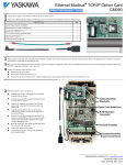
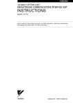
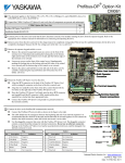
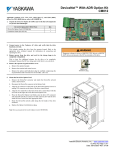
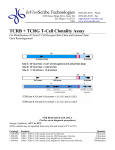
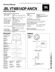
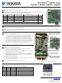
TM DeviceNet Option Card CM053, CM056, CM057, CM058 ! ! This document applies to the Yaskawa GPD515/G5, F7, G7 and P7 drives. Unpack the DeviceNet Option (CM05x) and verify that all components are present and undamaged. Check the EPROM label to verify that the DeviceNet Option (CM05x) card is the correct card for the drive. Drive Kit Number Option Board Number EPROM Label Designation G5 CM053 46S03318-001x VST80007x 1 F7 CM056 46S03318-002x VST80003x 1 G7 CM057 46S03318-003x VST80004x 1 P7 CM058 46S03318-004x VST80005x 1 DeviceNet Option (CM05x) Installation Guide (IG.AFD.14) ! ! ! ! Qty. 1 Connect power to the drive and verify that the drive functions correctly. This includes running the drive from the operator keypad. Refer to the appropriate drive technical manual for information on connecting and operating the drive. Remove power from the drive and wait for the charge lamp to be completely extinguished. Wait at least five additional minutes for the drive to be completely discharged. Measure the DC BUS voltage and verify that it is at a safe level. Remove the operator keypad and drive cover. # Remove the operator keypad and loosen any screws on the front of the terminal cover. Simultaneously pushing the locking tabs on the bottom right and left sides of the terminal cover inward, pull the bottom edge of the terminal cover outward. # Loosen any screws on the front of the control cover. Simultaneously pushing the locking tabs on the bottom right and left sides of the control cover inward, pull the bottom edge of the control cover outward. The drive control card should be visible. # Remove the option card hold-down on the left side of the drive case by carefully compressing the top and bottom until it becomes free of its holder. Lift it out. Mount the DeviceNet Option (CM05x) on the drive. # Align the J1 connector on the back of the DeviceNet Option (CM05x) with its mating 2CN connector on the drive control card. # Align the three standoffs on the front of the drive control board with the three holes on the right side of the DeviceNet Option (CM05x). # Press the DeviceNet Option (CM05x) firmly onto the drive 2CN connector and standoffs until the J1 connector is fully seated on 2CN and the drive standoffs have locked into their appropriate holes. # Replace the option card hold down. # Connect the ground wire from the ground terminal E on the option card to a ground terminal on the terminal assembly. ! Apply power to the drive and verify that the drive functions correctly. ! Connect to the DeviceNet network as shown in the figure to the right. Mounting the DeviceNet Option on an F7 drive Terminal Name 1 V- Black Wire Color Communication GND Description 2 CAN_L Blue CAN Data Low 3 Shield Bare Cable Shield 4 CAN_H White CAN Data High 5 V+ Red Communications +24Vdc Yaskawa Electric America, Inc – www.drives.com IG.AFD.14, Page 1 of 4 Date: 07/01/04, Rev: 04-07 ! Set the DeviceNet Option (CM05x) Baud Rate Set the Baud Rate for the DeviceNet Option (CM05x) to the network baud rate by setting DIP switches 1 an 2 as shown in the figure to the right. The baud rate must match the baud rate of the DeviceNet master (PC/PLC/Scanner) in order for the connection to function properly. ! Set the DeviceNet Option (CM05x) MAC ID Set the MAC ID of DeviceNet Option (CM05x) by setting DIP switches 3 through 8 as shown in the table below. Each device on the network must have a unique MAC ID, typically between 3 and 62. Addresses 0 and 1 are usually reserved for DeviceNet masters, address 2 for diagnostic/monitoring equipment and address 63 for vendor specific functions in some systems. Check the network schematic to verify the MAC ID setting. MAC ID Sw 00 01 02 03 04 05 06 07 08 09 10 11 12 13 14 15 16 17 18 19 20 21 22 23 24 25 26 27 28 29 30 31 3 0 0 0 0 0 0 0 0 0 0 0 0 0 0 0 0 0 0 0 0 0 0 0 0 0 0 0 0 0 0 0 0 4 0 0 0 0 0 0 0 0 0 0 0 0 0 0 0 0 1 1 1 1 1 1 1 1 1 1 1 1 1 1 1 1 5 0 0 0 0 0 0 0 0 1 1 1 1 1 1 1 1 0 0 0 0 0 0 0 0 1 1 1 1 1 1 1 1 6 0 0 0 0 1 1 1 1 0 0 0 0 1 1 1 1 0 0 0 0 1 1 1 1 0 0 0 0 1 1 1 1 7 0 0 1 1 0 0 1 1 0 0 1 1 0 0 1 1 0 0 1 1 0 0 1 1 0 0 1 1 0 0 1 1 8 0 1 0 1 0 1 0 1 0 1 0 1 0 1 0 1 0 1 0 1 0 1 0 1 0 1 0 1 0 1 0 1 Sw 1 2 Sw 9 MAC ID Sw 32 33 34 35 36 37 38 39 40 41 42 43 44 45 46 47 48 49 50 51 52 53 54 55 56 57 58 59 60 61 62 63 3 1 1 1 1 1 1 1 1 1 1 1 1 1 1 1 1 1 1 1 1 1 1 1 1 1 1 1 1 1 1 1 1 Sw 4 0 0 0 0 0 0 0 0 0 0 0 0 0 0 0 0 1 1 1 1 1 1 1 1 1 1 1 1 1 1 1 1 10 5 0 0 0 0 0 0 0 0 1 1 1 1 1 1 1 1 0 0 0 0 0 0 0 0 1 1 1 1 1 1 1 1 6 0 0 0 0 1 1 1 1 0 0 0 0 1 1 1 1 0 0 0 0 1 1 1 1 0 0 0 0 1 1 1 1 7 0 0 1 1 0 0 1 1 0 0 1 1 0 0 1 1 0 0 1 1 0 0 1 1 0 0 1 1 0 0 1 1 8 0 1 0 1 0 1 0 1 0 1 0 1 0 1 0 1 0 1 0 1 0 1 0 1 0 1 0 1 0 1 0 1 ! Baud Rate 125kbps 250kbps 500kbps 0 0 1 0 1 0 State 0 1 N/A 1 1 Function Always Set to 0 Reserved Master Idle Operation State Function 0 EF0 Disabled 1 EF0 Enabled A DeviceNet master is placed in “idle” mode if it remains connected but stops communicating. Sw 10 setting determines the drive response to a master in “idle” mode. Verify LED Status Refer to the table on the following page for a complete listing of LED states. LED MS MS MS NS NS Color Green Red Green Green Red LED Power-Up Sequence Condition On for 0.25 sec On for 0.25 sec On for 0.25 sec On for 0.25 sec On for 0.25 sec LED normal operation Status LED Condition MS Green Flash Green (No Communication) NS Green (Communicating) ! ! ! Param Remove power from the drive and wait for the charge lamp to be completely extinguished. Wait at least five additional minutes for the drive to be completely discharged. Measure the DC BUS voltage and verify that it is at a safe level. Function b1-01 Reference Selection b1-02 Operation Method Selection Reinstall all drive covers and the operator keypad. Apply power to the drive. Set parameters b1-01 and b1-02 to their appropriate values. Refer to the table to the right for available b1-01 and b1-02 values. Data 0 1 2 3 4 0 1 2 3 +/- Limits - Description Digital Operator Terminals Serial Communication Option PCB (DeviceNet Option) Pulse Input (F7 and G7 Only) Digital Operator Terminals Serial Communication Option PCB (DeviceNet Option) Dflt 1 1 Yaskawa Electric America, Inc – www.drives.com IG.AFD.14, Page 2 of 4 Date: 07/01/04, Rev: 04-07 ! Install the EDS File and Configure the Drive on the DeviceNet Network The EDS file can be obtained from the CD that was included with the drive or downloaded from www.drives.com. It is recommended that the EDS file be downloaded from www.drives.com to be sure that the latest version is used. Install the EDS file into the DeviceNet configuration tool (i.e. RSNetworx for DeviceNet). There is a separate EDS file for each drive model, verify that the correct EDS file has been installed for the drive model configured. Refer to the documentation that came with the master configuration tool for information on installing EDS files and configuring a DeviceNet node. Note: The EDS files located on the CD or downloaded from www.drives.com will be in “zip” format and will need to be un-zipped to a temporary directory prior to installation. ! LED Status Indicators and Diagnostics MS LED Condition Off Power Off Flashing Red Minor Fault Solid Red Unrecoverable Fault. Flashing Green Solid Green In Standby Normal – Communicating NS LED Off # # # # # # # # # # # # # # - Condition Power Off Flashing Red Incomplete Initialization Connection Time-Out Solid Red Critical Link Failure Flashing Green Normal – Not Communicating Solid Green Normal – Communicating # # # # # # # # # # # # # # Solution Check the drive main circuit wiring Check the connection of the option board to the 2CN connector on the drive Turn power on Check network termination Check network wiring Check baud rate Check that the communication bus wiring is separated from the main circuit wiring Check if MAC ID is unique per the network Check baud rate Check if the master is correctly configured Check if the termination resistors are correctly connected to the communication bus Check if the communication device is correctly connected per wiring diagrams Check if the communication bus wiring is separated from the main circuit wiring Check that the DeviceNet master has been configured for the drive Solution Check the drive main circuit wiring Check the connection of the option board to the 2CN connector on the drive Turn power on Wait for initialization to complete Check that the DeviceNet master is connected and on-line Check if MAC ID is unique per the network Check baud rate Check that the DeviceNet master is configured correctly Check that the termination resistors are correctly installed at the ends of the communication bus Check that the communications bus is not terminated any place other than at the ends Check that the drive is correctly connected per wiring diagrams Check that the communication bus wiring is separated from the main circuit wiring DeviceNet master is in “idle” mode Send an explicit or I/O message from the master as necessary Yaskawa Electric America, Inc – www.drives.com IG.AFD.14, Page 3 of 4 Date: 07/01/04, Rev: 04-07 TM DeviceNet Option Card CM053, CM056, CM057, CM058 Copies of this Installation Guide along with all technical manuals in “.pdf” format and support files may be obtained from either the CD supplied with the drive or from www.drives.com . Printed copies of any Yaskawa manual may be obtained by contacting the nearest Yaskawa office. Information on DeviceNet may be obtained from www.ODVA.org Reference documents: G5 Technical Manual – TM.4515 GPD515/G5 MODBUS Technical Manual – TM.4025 F7 Drive User Manual – TM.F7.01 F7 Drive Programming Manual – TM.F7.02 F7 Drive Parameter Access Technical Manual – TM.F7.11 G7 Drive Technical Manual – TM.G7.01 P7 Drive User Manual – TM.P7.01 P7 Drive Programming Manual – TM.P7.02 DeviceNet Option (CM05x) Installation Guide – IG.AFD.14 F7, G7, P7 DeviceNet Option (CM05x) Technical Manual – TM.AFD.14 G5 DeviceNet Option (CM053) Technical Manual – TM4556 DeviceNetTM is a trademark of the ODVA RSNetworx is a registered trademark of Rockwell Automation GPD is a trademark of Yaskawa, Inc. YASKAWA ELECTRIC AMERICA, INC. Drives Division 16555 W. Ryerson Rd., New Berlin, WI 53151, U.S.A. Phone: (800) YASKAWA (800-927-5292) Fax: (262) 782-3418 Internet: http://www.drives.com YASKAWA ELECTRIC AMERICA, INC. Chicago-Corporate Headquarters 2121 Norman Drive South, Waukegan, IL 60085, U.S.A. Phone: (800) YASKAWA (800-927-5292) Fax: (847) 887-7310 Internet: http://www.yaskawa.com MOTOMAN INC. 805 Liberty Lane, West Carrollton, OH 45449, U.S.A. Phone: (937) 847-6200 Fax: (937) 847-6277 Internet: http://www.motoman.com YASKAWA ELECTRIC CORPORATION New Pier Takeshiba South Tower, 1-16-1, Kaigan, Minatoku, Tokyo, 105-0022, Japan Phone: 81-3-5402-4511 Fax: 81-3-5402-4580 Internet: http://www.yaskawa.co.jp YASKAWA ELETRICO DO BRASIL COMERCIO LTDA. Avenida Fagundes Filho, 620 Bairro Saude Sao Paolo-SP, Brasil CEP: 04304-000 Phone: 55-11-5071-2552 Fax: 55-11-5581-8795 Internet: http://www.yaskawa.com.br YASKAWA ELECTRIC EUROPE GmbH Am Kronberger Hang 2, 65824 Schwalbach, Germany Phone: 49-6196-569-300 Fax: 49-6196-888-301 MOTOMAN ROBOTICS AB Box 504 S38525, Torsas, Sweden Phone: 46-486-48800 Fax: 46-486-41410 MOTOMAN ROBOTEC GmbH Kammerfeldstrabe 1, 85391 Allershausen, Germany Phone: 49-8166-900 Fax: 49-8166-9039 YASKAWA ELECTRIC UK LTD. 1 Hunt Hill Orchardton Woods Cumbernauld, G68 9LF, Scotland, United Kingdom Phone: 44-12-3673-5000 Fax: 44-12-3645-8182 YASKAWA ELECTRIC KOREA CORPORATION Paik Nam Bldg. 901 188-3, 1-Ga Euljiro, Joong-Gu, Seoul, Korea Phone: 82-2-776-7844 Fax: 82-2-753-2639 YASKAWA ELECTRIC (SINGAPORE) PTE. LTD. Head Office: 151 Lorong Chuan, #04-01, New Tech Park Singapore 556741, Singapore Phone: 65-282-3003 Fax: 65-289-3003 TAIPEI OFFICE (AND YATEC ENGINEERING CORPORATION) 10F 146 Sung Chiang Road, Taipei, Taiwan Phone: 886-2-2563-0010 Fax: 886-2-2567-4677 YASKAWA JASON (HK) COMPANY LIMITED Rm. 2909-10, Hong Kong Plaza, 186-191 Connaught Road West, Hong Kong Phone: 852-2803-2385 Fax: 852-2547-5773 BEIJING OFFICE Room No. 301 Office Building of Beijing International Club, 21 Jianguomanwai Avenue, Beijing 100020, China Phone: 86-10-6532-1850 Fax: 86-10-6532-1851 SHANGHAI OFFICE 27 Hui He Road Shanghai 200437 China Phone: 86-21-6553-6600 Fax: 86-21-6531-4242 SHANGHAI YASKAWA-TONJI M & E CO., LTD. 27 Hui He Road Shanghai 200437 China Phone: 86-21-6533-2828 Fax: 86-21-6553-6677 BEIJING YASKAWA BEIKE AUTOMATION ENGINEERING CO., LTD. 30 Xue Yuan Road, Haidian, Beijing 100083 China Phone: 86-10-6232-9943 Fax: 86-10-6234-5002 SHOUGANG MOTOMAN ROBOT CO., LTD. 7, Yongchang-North Street, Beijing Economic & Technological Development Area, Beijing 100076 China Phone: 86-10-6788-0551 Fax: 86-10-6788-2878 YEA, TAICHUNG OFFICE IN TAIWAIN B1, 6F, No.51, Section 2, Kung-Yi Road, Taichung City, Taiwan, R.O.C. Phone: 886-4-2320-2227 Fax:886-4-2320-2239 Data subject to change without notice. Yaskawa Electric America, Inc – www.drives.com IG.AFD.14, Page 4 of 4 Date: 07/01/04, Rev: 04-07