1
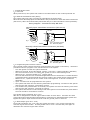
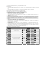
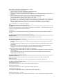
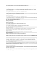
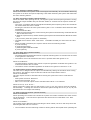
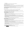
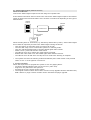
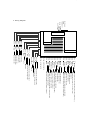
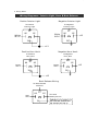
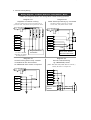
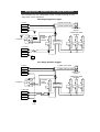
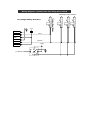
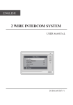
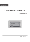
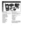
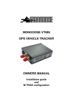
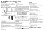
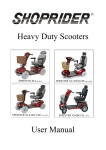
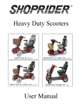
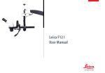
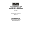
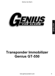
-
FA L CON
WORLD CLASS SE CURITY
FALCON PREDATOR XL3
Vehicle Security System with Anti-Hijack
Installer’s Manual
TABLE OF CONTENTS
1. SYSTEM INSTALLATION ............................................... 2
1.1. Power On ........................................................... 2
1.2. NO & NC Immobiliser Relay Wiring ......................... 2
1.3. Programming New Remote Controls ....................... 2
1.4. Bypass Input (red/black wire: w3-7) ...................... 2
1.5. Start Output (pink wire: w3-9) .............................. 2
1.6. Interior Light Supervision (green/white wire: w3-6).. 3
1.7. Program the Optional Features (default=1 chirp)...... 3
1.8. Optional Programmable Features ........................... 3
1.9. Feature #20 Override Code (default=1 flash) .......... 4
1.10. Explanation of the Optional Features..................... 4
2. SYSTEM UPGRADE ...................................................... 8
3. Wiring Diagram .......................................................... 9
4. Wiring Notes............................................................ 10
5. Central Locking Wiring .............................................. 11
1. SYSTEM INSTALLATION
1.1. Power On
When powered on, the system will remain in the same status it was in when powered off.
1.2. NO & NC Immobiliser Relay Wiring
The system offers two ways of wiring the immobiliser as shown below.
When wired for Normally Open the immobiliser relay is switched on when the alarm is disarmed
(fail secure). When wired as Normally Closed the relay is on when the alarm is armed (fail safe).
Wiring Diagram - Immobiliser Relay NO & NC
Normally Open Immobiliser Connection (Fail Secure)
Start
To Acc.
On
Acc
86
Off
87
30
85
fig. 1
87a
87a - Normally Closed
87 - Normally Open
W2-7
Normally Closed Immobiliser Connection (Fail Safe)
Start
To +12V DC or Acc.
87
On
Acc
86
Off
30
85
fig. 2
W2-8
87a
87a - Normally Closed
87 - Normally Open
1.3. Programming New Remote Controls
The included remote controls have been programmed to the system in the factory. Follow the
procedure below to program a new remote control to the system:
- Turn the ignition on with the system disarmed.
- Within 10 seconds, press valet switch 3 times. (or 6 times if pager upgrade is installed).
- The siren sounds for 2 sec. to confirm the system is now in code learning mode.
- Within 10 sec., press any button of 1st remote control
The siren will sound for 1 sec. and hazard lights flash twice to confirm the 1st remote has been
programmed to the system and all the previous codes in the system will be erased entirely.
- Within 10 sec., repeat for the 2nd remote control and again for 3rd and 4th remotes as
applicable.
* Up to 4 remotes can be programmed to the system
* The system will leave the code learning mode after programming 4 remotes to the system
and the siren will sound for 2 seconds to confirm.
* If no buttons are pressed within 10 seconds, the system will leave the learning code mode
and the siren will sound for 2 seconds to confirm.
* The system will leave the code learning mode if the ignition is turned off at any time and the
siren will sound for 2 seconds to confirm.
1.4. Bypass Input (red/black wire: w3-7)
This wire is designed for external engine start module or turbo timer. Feed this wire with
ground when the external engine start module or turbo timer is activated and the system will
bypass the ignition input and shock sensor until the ground pulse is removed.
1.5. Start Output (pink wire: w3-9)
Press and hold button #4, 3 sec. later the system will send a 1 sec. pulse to activate the
external engine start module. Pressing button #4 for 3 sec. will send the pulse again to
deactivate the external engine start module.
-
1.6. Interior Light Supervision (green/white wire: w3-6)
If connected:
- The interior light will be turned on for 20 sec. when disarming unless the ignition is turned
on.
- The interior light will be turned on all the time whilst the alarm is sounding.
1.7. Program the Optional Features (default=1 chirp)
Follow the steps below to program the Optional Features:
For example: To program the feature #5 as 15sec.
-
Turn the ignition on then off with the system disarmed.
Within 10 sec., press the valet switch 3 times.
The system enters the programming mode and the siren and LED will be on for 2 sec. to
confirm.
* To Reset to Factory Default:
Within 10 seconds press button #4 for 3 sec., all the optional features will be reset to the
factory default and the siren will sound for 2 sec. to confirm leaving the programming
mode.
- Within 10 sec., press the valet switch 5 times.
- 1 sec. later the siren will chirp 5 times to confirm.
- Press button #1 of the remote control 6 times to select 15 sec. and the siren will chirp 6
times to confirm the setting.
- Press the valet switch again (from 1 to 21) within 10 sec. to select the next feature for
programming.
* The system will leave the programming mode and the siren will sound for 2 sec. to confirm
if the ignition is turned off at any time during programming or if the valet switch or remote
control button #1 has not been pressed within 10 sec.
1.8. Optional Programmable Features
No
1
2
3
4
5
Chirp
1 chirp
2 chirp
3 chirp
4 chirp
5 chirp
Function
Chirp Confirmation
Door Lock with Passive Arming
Ignition Lock
Ignition Unlock
Door Lock Time(sec.)
6 6 chirp
Door Unlock Time(sec.)
7 7 chirp
Door Unlock with Disarming
8 8 chirp
Siren/Horn Output
9 9 chirp
Alarm Condition Cycle Duration
10 10 chirp
Interior Light Delay
11 11 chirp
Auto. Rearming
12 12 chirp
Auto. Engine Disable(AED)
13 13 chirp
Door Open Alerts
14 14 chirp
Total/Comfort Closure
15 15 chirp
Disarm with Boot Release
16 16 chirp
Anti-hijacking Countdown
17 17 chirp Activate Anti-hijacking Countdown
18 18 chirp
Anti-hijacking by Remotes
19 19 chirp Anti-hijacking by Ignition+Door
20 20 chirp
Override Code
21 21 chirp
Hazard lights Output
Factory Default = 1 Chirp
Τ
1 Chirp
On
Disable
Disable
Disable
1) 0.8
0.8
Driver
Siren
30 sec.
Disable
Disable
Disable
Disable
Disable
Disable
30sec.
Normal
Disable
Disable
Flash 1
Normal
Τ
2 Chirp Τ
Off
Enable
Ignition
Driver
2) 3.6
5) 0.8+40
3.6
All
Horn
60 sec.
25 sec.
Enable
Enable
Mode 1
15 sec.
Enable
60sec.
Brake
Enable
Enable
Pulse
3 Chirp
Brake
All
3) 0.8*2
6) 15
0.8*2
Τ
4 Chirp
4) 0.8+15
7) 40
40 sec.
60 sec.
Mode 2
30 sec.
40 sec.
Flash 2~10
Continuous
-
1.9. Feature #20 Override Code (default=1 flash)
Follow the steps below to program:
- Turn the ignition on then off with the system disarmed.
- Within 10 sec., press the valet switch 3 times.
- The system enters the programming mode and the siren and LED will be on for 2 sec. to
confirm.
- Within 10 seconds press the valet switch 20 times to select feature #20
- 1 sec. later the siren will chirp 20 times to confirm the selection.
- The LED will start to flash 10 times slowly 2 sec. later.
- Press button #1 of remotes after the LED has flashed the number of times you want to set
the code to; Eg. If you want to choose 6 as the code then press button #1 once after the
LED has flashed 6 times. The LED will turn off and siren sound for 1 sec. to confirm.
- Press the valet switch within 10 sec., to select the next feature for programming.
1.10. Explanation of the Optional Features
01. Chirp Confirmation On/Off(default=on)
When On:
The siren will chirp once for system arming and twice for disarming. With this feature on, the
silent arm/disarm button is still functional.
When Off:
The siren will not chirp for system arming and disarming but the hazard lights will flash as
normal.
02. Door Lock with Passive Arming(default=disable)
When Enabled:
The doors will also be locked when the system passively arms itself.
03. Ignition Lock (default=disabled)
When set as Ignition:
- The doors will be locked 15 sec. after turning the ignition on if all the doors are closed
properly.
- The doors will not be locked if a door is not closed or has been opened during the 15 sec.
countdown.
- If the doors are unlocked during driving they will be locked again automatically after
stepping on the brake pedal. (Brake light wire must be connected).
When set as Brake: (Brake light wire must be connected)
- The doors will be locked when the brake is tapped with the ignition on if all the doors are
closed properly.
- If the doors are unlocked during driving they will be locked again automatically after
stepping on the brake pedal.
04. Ignition Unlock(default=disable)
When set as Driver:
After parking the car the drivers door will be unlocked when turning the ignition off.
When set as All:
After parking the car all the doors will be unlocked after turning the ignition off.
05. Door Lock Time (default=0.8)
When set as 0.8 sec.:
The system will send a 0.8 sec. pulse when locking the doors.
When set as 3.6 sec.:
The system will send a 3.6 sec. pulse when locking the doors.
When set as 0.8 sec.*2:
The system will send two 0.8 sec. pulses when locking the doors.
When set as 0.8 sec. + 15 sec.:
The system will send a 0.8 sec. pulse and then send a 15 sec. pulse when locking the doors.
-
*When selecting 0.8 sec. + 15 sec. for cars with total closure the windows will be closed
automatically during remote arming without enabling feature #14.
When set as 0.8 sec. + 40 sec.:
The system will send a 0.8 sec. pulse and then send a 40 sec. pulse when locking the doors.
*When selecting 0.8 sec. + 40 sec. for cars with total closure the windows will be closed
automatically during remote arming without enabling feature #14.
When set as 15 sec.:
The system will send a 15 sec. pulse when locking the doors.
*When selecting 15 sec. for cars with total closure the windows will be closed automatically
during remote arming without enabling feature #14.
When set as 40 sec.:
The system will send a 40 sec. pulse when locking the doors.
*When selecting 40 sec. for cars with total closure the windows will be closed automatically
during remote arming without enabling feature #14.
06. Door Unlock Time (default=0.8 sec.)
When set as 0.8 sec.:
The system will send a 0.8 sec. pulse when unlocking the doors.
When set as 3.6 sec.:
The system will send a 3.6 sec. when unlocking the doors.
When set as 0.8 sec.*2:
The system will send two 0.8 sec. pulses when unlocking the doors.
07. Door Unlock with Disarming (default=driver)
When set as Driver:
Only the drivers door will be unlocked when pressing button #2 to disarm the system.
Pressing button #2 again within 3 seconds will unlock the rest of the doors.
When set as All:
All the doors will be unlocked when pressing button #2 to disarm the system.
08. Siren/Horn Output (default=siren)
When set as Siren:
Select the Siren option when connecting an external siren.
When set as Horn:
Select the Horn option when connecting the output to the cars horn. Note a relay must be used.
09. Alarm Condition Cycle Duration (default=30 sec.)
When set as 30 sec. or 60 sec.:
The siren will sound for 30 sec. (or 60 sec) when the system is triggered and released. The
siren will sound for 30 sec. (or 60sec) x 3 cycles if the system is triggered continuously.
10. Interior Light Delay (default=disable=5 sec.)
When set as Disable (=5 sec.):
The siren chirps 3 times and the hazard lights flash 3 times immediately if any of the doors, boot
or bonnet are not closed properly when remote arming the system. The relevant input will be
bypassed until the door/boot/bonnet is closed.
When set as 25-40-60 sec.:
The siren chirps 3 times and hazard lights flash 3 times immediately when remote arming the
system if the boot or bonnet are not closed properly. The boot & bonnet will be bypassed until
both are closed properly.
The siren chirps 3 times and hazard lights flash 3 times in 25sec.(or 40, 60sec.) after remote
arming the system if the doors are not all closed properly. The doors will be bypassed until they
are all closed properly.
-
11. Auto. Rearming (default=disable)
When set as Enable: The system will arm itself again automatically 30 seconds after disarming
the system if no doors are opened. Opening a door after disarming the system will deactivate
the auto rearming feature.
12. AED, Auto Engine Disable (default=disable)
When as Enable: After parking the car, turning the ignition off and opening and then closing
the door the engine disable relay will activate within 10 seconds but the system will still be
disarmed.
- The 10 sec. countdown will be interrupted immediately when opening a door, the countdown
will restart when the door is closed.
- Pressing the remote to arm the system during the 10 sec. countdown will activate the AED
immediately.
- To deactivate the AED:
a) With the system disarmed, remote arming the system then disarming will deactivate the
AED at the same time.
b) With the system armed, remote disarming the system will deactivate the AED at the same
time.
c) By override (when the system is disarmed).
* The AED will not active under valet mode. To disable the AED you must leave the valet
mode.
* When the AED is activated, the system cannot enter the following modes:
a) Code Learning
b) Programming Mode
c) Hazard lights Calibration Mode
d) Anti-hijacking
13. Door Open Alerts (default=disable)
When set as Mode 1:
- The hazard lights will flash when a door is opened with the ignition on until the door is closed
or the ignition is turned off.
* The feature will not be activated if the door is opened whilst the ignition is on.
When set as Mode 2:
- The hazard lights will flash when a door is opened regardless of whether the ignition is on
of off and until the door is closed.
* The feature will be activated regardless of whether the ignition is turned on or off.
14. Total/Comfort Closure (default=disable)
The CH3 wire is designed for the option of automatically closing the windows when arming
the system. This feature requires that the vehicle has Total/Comfort Closure.
When set as Disable:
The CH3 output will not be activated when arming the system but can be controlled as
follows:
- With system armed or disarmed.
- Press and hold button #1+3.
- After 1 sec. the CH3 output will be activated until button #1 is released.
When set as 15, 30 or 40 sec.:
When arming the system the CH3 will send a 15 sec.(or 30, 40) pulse to close the windows
automatically. Pressing the remote to disarm the system during the 15 sec.(or 30, 40) will
deactivate the CH3 output immediately.
15. Disarm with Boot Release (default=disable)
When set as Disable:
When operating the remote boot release the system will remain armed but the shock sensor
will be bypassed. The boot will be protected and shock sensor reactivated 3 sec. after
closing the boot.
When set as Enable:
The system will be disarmed when operating the boot release, the siren will chirp twice and
hazard lights flash twice to confirm.
* The countdown of Auto. Rearming or Passive Arming will be interrupted when operating the
-
boot release.
* The remote boot release will still work with the ignition on.
16. Anti-hijacking Countdown (default=30sec.)
When set as 30 or 60 sec.:
The system will enter the Anti-hijacking mode after 30 or 60 sec. depending on the selection.
The siren will chirp 10 times before entering into the anti-hijacking mode as a last warning.
17. Activate Anti-hijacking Countdown (default=normal)
When set as Normal:
The countdown will start immediately when activating the anti-hijacking feature.
When set as Brake:
The system will enter the Anti-hijacking mode after the footbrake is tapped.
* After the system starts the countdown, press the valet switch before the last 10 chirps
warning to stop the countdown and deactivate the anti-hijacking.
18. Anti-hijacking by Remotes (default=disable)
When set as Enable:
The Anti-hijacking will be activated as follows:
- With the system disarmed and the ignition on.
- Press button #1 for 2 sec. to activate the anti-hijacking and the hazard lights flash once to
confirm.
- The anti-hijacking countdown will start depending on the selection of feature #17. The LED
will flash every 2 secs. once the countdown starts.
- After 30 or 60 sec. depending on the selection of feature #16, the system enters the
Anti-hijacking mode. 10 sec. before the countdown ends, the siren and hazard lights will
activate as a warning.
- When the system is in anti-hijacking mode, the siren will sound and hazard lights flash until
the system is overridden using the emergency override procedure.
19. Anti-hijacking by Ignition+Door (default=disable)
When set as Enable:
The Anti-hijacking will be activated as follows:
- With the system disarmed and the ignition on.
- Opening and closing a door will activate the anti-hijacking and the hazard lights will flash
once to confirm.
- The anti-hijacking countdown will start depending on the selection of feature #17. The LED
will flash every 2 secs. once the countdown starts.
- After 30 or 60 sec. depending on the selection of feature #16, the system enters the
Anti-hijacking mode. 10 sec. before the countdown ends, the siren and hazard lights will
activate as a warning.
- When the system is in anti-hijacking mode, the siren will sound and hazard lights flash until
the system is overridden using the emergency override procedure.
20. Override Code (default= flash 1)
- Follow Section 1.9 to change the Override Code.
- Follow Section 2.6b of the user manual to operate the Override.
-
21. Hazard lights Output (default=normal)
When set as Normal:
Connect the hazard lights output as normal using the Y-splitter lead.
If the Normal connection does not work then connect the hazard lights output to the hazard
switch as shown below and set feature #21 as Pulse or Continuous depending on the type of
hazard switch
Hazard
Switch
Hazard
Lights
O
Control Unit
I
Hazard Lights
Output
Predator
XL3
When selecting Pulse or Continuous, try the factory default first (0.5sec). If the hazard lights
do not flash as expected proceed to the hazard light learning as follows:
- Turn the ignition on and off 3 times (on-off-on-off-on-off).
- The siren will chirp once to confirm the system is in learning mode.
- Turn the vehicles hazard lights on and the hazard lights start to flash.
- Within 10 sec. press and hold the valet switch.
- The LED will turn on to confirm the valet switch is pressed.
- Release the valet switch once the hazard lights have flashed 10 times.
- The LED will turn off and siren will chirp once to confirm the learning is complete.
* The system will leave the learning mode automatically if the valet switch is not pressed
within 10 sec. or if the ignition is turned on.
2. SYSTEM UPGRADE
Follow the steps below to upgrade the system to a 2-way paging alarm.
- Cut off the Red and White loops next to port W-1 (main unit).
- Plug the 2-way transceiver into port W-1.
- Program the 2-way remotes to the system.
* The original remote controls will not work once the 2-way upgrade has been installed. Only
EVO 4 button or pager remote controls can be used with the pager upgrade.
-
3. Wiring Diagram
W1-Plug-in
2Way
Transceiver
Red
White
W8-1
W8-2
W8-3
W8-4
W8-5
W8-6
W3-0
W3-1
W3-2
W3-3
W3-4
W3-5
W3-6
W3-7
W3-8
W3-9
W2-1
W2-2
W2-3
W2-4
W2-5
W2-6
W2-7
W2-8
Green
Purple
Black/Red
Gray
Gray/black
Blue/White
Green/White
Red/Black
Blue
Pink
White/Red
White
Black
Yellow
Red
Brown
Orange/Black
Orange
W4 Plug-in LED indicator
W5 Plug-in Valet switch
To ground or +12V depending on polarity of W2-2 (+/-)
Hazard lights output (+/- built-in relay)
To ground
Ignition trigger input
To +12V battery
Siren/Horn output (1A)
Immobiliser output (normally open/-500mA)
Immobiliser output (normally closed/-500mA)
Door trigger input (-)
Door trigger input (+)
To footbrake light
Boot release output (-500mA)
Total/Comfort closure output (-500mA)
Door unlock2 output (-500mA)
Interior light output (-500mA)
Bypass input from optional remote starter module
Boot/Bonnet trigger input
Remote starter module output (-500mA)
Auxiliary sensor 2nd stage input
Ground
Auxiliary sensor 1st stage input
+12v
W6-1
Black
Ground
Shock sensor 2nd stage input
Shock sensor 1st stage input
Red
Green
W6-2
W6-3
W7-1
Blue
lock (nc)
lock (com)
lock (no)
unlock (nc)
unlock (com)
unlock (no)
+12v
W6-4
W7-2
Black
Red
Door
Door
Door
Door
Door
Door
W7-3
W7-4
Black
Green
Pink
White
Blue
Orange
-
4. Wiring Notes
Wiring Diagrams - Interior Light, Horn & Boot Release
Postive Interior Light
Negative Interior Light
To Positive
Interior Light
To Negative
Interior Light
White
W3-6
87
86
85
White
W3-6
87a
87
86
85
+12
87a
30
30
+12
Positive Horn Honk
Negative Horn Honk
To Positive
Horn Wire
To Negative
Horn Wire
86
Brown
W2-6
87
86
85
Brown
W2-6
87a
87
85
87a
30
30
+12
Boot Release Wiring
To Boot Release
Solenoid
86
Gray
W3-3
87
87a
30
85
To Fused
Battery Source
CONNECT TO A FUSED +12
OR GROUND DEPENDING
ON WIRING OF PIN 87
+12
-
5. Central Locking Wiring
Wiring Diagram - Predator XL3 Door Lock/Unlock - Basic
Follow the diagrams below for wiring basic central locking systems
Diagram #A
Negative or Positive Locking
Diagram #B
Motor Interrupt Locking eg. CHRYSLER
Two wires resting open circuit one pulses 12V or
ground for lock, one pulses 12V or ground for unlock
Two wires resting at ground, one pulses
12V for lock, one pulses 12V for unlock
Up
Black
Black
Green
Green
Pink
Pink
White
White
Blue
Blue
Orange
Orange
To +12V or Ground
Depending on polarity
of locking system
+12V
Original Built-in
Controller
Diagram #C
Central locking where only a switch
is installed in the drivers door.
An additional door motor is required.
Door Lock Switch
On the Front Door
Diagram #D
Vacuum central locking
eg: MERCEDES, AUDI
(Note: Set door lock/unlock time to 3.6 sec.)
Polarity Reverses on a single wire
Black
Green
Black
Green
+12V
Pink
Down
Blue
Pink
Orange
White
Blue
Orange
White
Up
Main Line
Electric Motor
Switch
Up
Down
-
Wiring Diagram - Predator XL3 Two Stage Door Unlock
The Predator XL3 has a dedicated unlock-2 output allowing for two
stage door unlock operation.
Two Stage Negative Trigger
(-)LOCK
(-)DOOR LOCK WIRE
Black
L
(-)DOOR UNLOCK WIRE
Green
UL
DOOR LOCK
SWITCH
Pink
PASSENGER DOOR
MOTORS
+12V
86
(-)UNLOCK-2
87
85
87a
15A
DRIVERS
DOOR
MOTOR
30
FACTORY
DOOR LOCK
MODULE
(-)UNLOCK
White
Blue
Orange
15A
+12V
Two Stage Positive Trigger
(+)LOCK
(+)DOOR LOCK WIRE
Black
L
(+)DOOR UNLOCK WIRE
Green
UL
DOOR LOCK
SWITCH
Pink
PASSENGER DOOR
MOTORS
86
(-)UNLOCK-2
87
85
87a
DRIVERS
DOOR
MOTOR
30
(+)UNLOCK
White
Blue
Orange
15A
+12V
FACTORY
DOOR LOCK
MODULE
-
Wiring Diagram - Predator XL3 Two Stage Door Unlock
Passenger Door Motors
Two Stage Adding Actuators
+12V
Black
15A
LOCK
Green
Pink
White
UNLOCK
Blue
+12V
Orange
86
(-)Unlock-2
87
87a
30
85