1
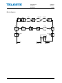
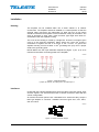
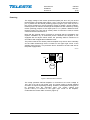
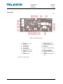
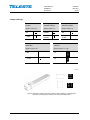
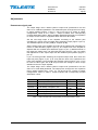
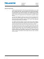
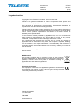
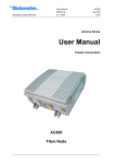
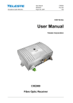
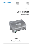
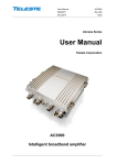
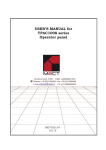
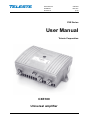
User Manual
CXE180
59300401
Rev.001
26.5.2010
1(12)
CXE Series
User Manual
Teleste Corporation
CXE180
Universal amplifier
User Manual
CXE180
59300401
Rev.001
26.5.2010
2(12)
Contents
Introduction ........................................................................................................ 3
Technical specifications ................................................................................... 4
Block diagram .................................................................................................... 5
Installation .......................................................................................................... 6
Housing ................................................................................................................ 6
Interfaces ............................................................................................................. 6
Powering .............................................................................................................. 7
Front panel ........................................................................................................... 8
Jumper settings ................................................................................................... 9
Adjustments ..................................................................................................... 10
Downstream signal path .................................................................................... 10
Upstream signal path ......................................................................................... 11
Legal declarations ........................................................................................... 12
User Manual
CXE180
59300401
Rev.001
26.5.2010
3(12)
Introduction
CXE180 is a compact dual output amplifier. It has two gain modes in one
product. Gain can be selected on the field according to wanted operation.
Higher gain (40 dB) is designed for distribution purposes and lower gain (32
dB) is suitable for line extender use. CXE180 house distribution amplifier
supports 1 GHz frequency range in the downstream and up to 85 MHz in the
upstream.
Adjustments use electrical controls thus eliminating the need of the usual plugin attenuators in the system set-up. Other standard features include reliable
power supply, built-in US amplifier as well as an efficient surge and ESD
protection.
Caution!
− Services and repairs should only be carried out by
authorised personnel.
− Do not touch live parts.
− The amplifier has no separate power switch thus
the power plug must be easily accessible.
− The power must be cut when installing or removing the
amplifier.
− The amplifier must not be operated without its Standard fitted
power supply unit protection cover. The lid must be closed.
User Manual
CXE180
59300401
Rev.001
26.5.2010
4(12)
Technical specifications
Downstream signal path ( all values with the diplex filters)
Frequency range
47 / 54 / 70 / 85 / 108..1006 MHz
Return loss
18 dB
Gain
40.0 dB
Input attenuator control range
0...15 dB @ 1 dB
Input equaliser control range
0...20 dB @ 2 dB
Cable simulator
0 / -8 dB
Mid-stage slope
0 dB / 8 dB
Mid-stage gain selection
40.0 dB / 32.0 dB
Flatness
± 0.5 dB
Noise figure
7.0 dB
Output level, CTB CENELEC 42 ch
112.0 dBμV
Output level, CSO CENELEC 42 ch
114.0 dBμV
Output level, XMOD CENELEC 42 ch
111.0 dBμV
Upstream signal path (return module and diplex filters are installed into the CXE202)
Frequency range
5...30 / 42 / 50 / 65 / 85 MHzMHz
Return loss
18 dB
Gain
28.0 dB
Gain control range (output)
0... -15 dB @ 1 dB
Gain control range (input)
0 / -10 dB
Slope control range
0...15 dB @ 1 dB
Flatness
± 0.75 dB
Noise figure
5.0 dB
Output level, DIN 45004B
114.0 dBμV
General
Power consumption
14 W
Supply voltage
26...65 V AC, 180…255 V AC
Maximum current feed through
3.0 A / port
Input / Output connectors
PG11 (several adaptors available)
Test point connectors
F female (20 dB)
Dimensions (h x w x d)
140 (148) mm x 182 (210) mm x 84 mm
Weight
1.5 kg
Operating temperature
-40...+55 °C
Class of enclosure
IP54
EMC
EN 60728-2
Additional EMC tests for RF ports
ESD 4 kV / Surge 4 kV
All specifications are subject to change without notice
User Manual
CXE180
59300401
Rev.001
26.5.2010
5(12)
Block diagram
Flat
High gain
Sloped
Low gain
Flat
dB
Cable simulation
0 dB
dB
-10 dB
TP -20dB
TP -20dB
AC
IN
AC
OUT 2
AC
OUT 1
User Manual
CXE180
59300401
Rev.001
26.5.2010
6(12)
Installation
Housing
The amplifier can be installed either into a street cabinet or to outdoor
environment. The amplifier should be installed in a vertical position so that the
external cable connectors are underneath. At least 100 mm of free space
should be left above the amplifier to ensure sufficient cooling air circulation. The
class of enclosure is IP54. Note, used connector type might have lower IPclassification than the amplifier housing.
The cover of the housing is closed by a single bolt. There are no hinges. Open
cover is to be removed completely. When closing the cover use a PZD 2
screwdriver to tighten the bolt to a torque of 2.5...3.5 Nm. To ground the
2
amplifier housing connect at least 4 mm grounding wire (Cu) from a proper
earth to the grounding point.
NOTE! Make sure the input attenuator adjustment (Figure 4 pos. 5) is at its
minimum level before connecting power to the amplifier.
8910044
Figure 1. CXE180 amplifier
1) Input, 2) Ground, 3) Output port 2, 4) Output port 1
Interfaces
Underneath the CXE180 amplifier there are three cable connection points: input
and two outputs. The amount and function of actual connectors varies with the
chosen configuration.
All coaxial connection points have a standard PG11 thread and they accept a
KDC type adapter or connector. Available connector types are F, IEC, PG11,
5/8” and 3.5/12.
8905010
Figure 2. Centre conductor length
User Manual
CXE180
59300401
Rev.001
26.5.2010
7(12)
Powering
The supply voltage of the remote powered amplifier (26...65 V AC) can be fed
through either f the output ports (Figure 1 pos. 3 & 4) or the input port (Figure 1
pos. 1). Make sure the remote powering jumpers (Figure 4 pos. 20 & 21) are in
the correct positions for remote powering. Refer to chapter ‘Jumper settings’.
External power can also be fed through the amplifier into the network by moving
remote powering jumpers of the output ports to “on” position. Maximum feedthrough current is 3 A per port (6 A total). When F connector is used, a remote
current should be lower than 2 A.
Note that the external wiring connected to terminals that are hazardous live
requires installation by an instructed person. Because the amplifier is not
equipped with an all-pole mains switch, the powering shall be carried out in
accordance with all applicable installation rules.
The power intake of the remote powered amplifier may also be done externally
via the cable feed-through that is located on the upper right corner of the
amplifier (see Figure 3). The protective fuse is located on the left hand side of
the power supply board.
8907016
AC
GND
FUSE
Figure 3. Remote cable connector
The locally powered CXE180 amplifier is connected to the main voltage of
180…255 V AC via its own power cord. The power supply is double shielded
and does not require separate grounding. However, the amplifier housing has to
be grounded from the grounding point. The supply voltage fuse
(T3.15 A / 250 V) is located on the upper right corner of the amplifier,
underneath the remote cable connector (Figure 3).
User Manual
CXE180
59300401
Rev.001
26.5.2010
8(12)
Front panel
8910051
Figure 4. CXE180 Front panel
1)
2)
3)
4)
5)
6)
7)
8)
9)
RF input
Input test point, -20 dB
transformer
Input diplex filter
Input attenuator
Input equaliser
Cable simulator *)
Mid stage gain selection
jumper *)
Mid stage slope selection
jumper *)
Output diplex filter
*) See chapter ‘Jumper settings’
10) Output test point, -20dB
directional coupler
11) Output module (see table 1)
12) RF output 1
13) RF output 2
14) Return path input attenuator
*)
15) Return path equaliser
16) Return path attenuator
17) Remote powering jumper for
outputs *)
18) Remote powering jumper for
input *)
User Manual
CXE180
59300401
Rev.001
26.5.2010
9(12)
Jumper settings
Cable simulator
jumper
Mid stage gain
selection jumper
Mid stage slope
selection jumper
(Figure 4 pos. 6)
(Figure 4 pos. 7)
(Figure 4 pos. 8)
flat
high gain
(40 dB)
flat
- 8 dB
low gain
(32 dB)
Sloped
(8 dB)
Return path
attenuator
Remote power
jumpers
(Figure 4 pos. 14)
(Figure 4 pos. 17, 18)
0 dB
on
- 10 dB
off
8610040
Figure 5. Illustration of the jumper plug used for cable simulation, mid stage gain
selection, mid stage slope selection and return path attenuation
User Manual
CXE180
59300401
Rev.001
26.5.2010
10(12)
Adjustments
Downstream signal path
The output stage uses a GaAs hybrid to improve RF performance over the
entire 47 to 1006 MHz passband. The distribution path, through the use of plugin output modules (Figure 4 pos.11), can be set up for a variety of output
configurations. Refer to the ‘Table 1. Output modules with corresponding
nominal attenuation values’. During amplifier adjustment the plug-in unit position
for output module must be equipped at least with the 0 dB module.
Set the mid stage slope of the amplifier according to the network plan
calculation by means of the mid stage slope selection jumper (Figure 4 pos. 8).
The available options are “flat” (0 dB) or “sloped” (8 dB).
Set the output slope of the amplifier according to the network plan calculation by
means of cable simulator (Figure 4 pos. 6). The output level of the amplifier is
adjusted with the variable input attenuator (Figure 4 pos. 4). Measurements on
the output are made at the -20 dB output test point (Figure 4 pos. 10). Make
final adjustment of the output slope with the variable input equaliser (Figure 4
pos. 5).
If you are having trouble obtaining the expected output level then check the
input test point (Figure 4 pos. 2) to verify that the level is as expected at the
input of the amplifier. The mid stage gain selection jumper (Figure 4 pos. 7) can
be used to reduce gain with 8 dB if input levels are enough to cause a high
distortion level in the input amplifier.
The output stage uses a GaAs hybrid to improve RF performance over the
entire 47 to 1006 MHz passband. The output ports, through the use of passive
plug-in output modules (Fig. 4 pos. 11); can be set up for a variety of output
configurations. Refer to ‘Table 1. Output modules with corresponding nominal
attenuation values’.
Module
AC6120
AC6112
AC6116
AC6119
AC6124
AC6128
Functionality
0 dB output module, 1 output in use
1/12 dB tap, 2 outputs in use
1/16 dB tap, 2 outputs in use
1/20 dB tap, 2 outputs in use
Two-way splitter, 2 outputs in use
2/9 dB tap, 2 outputs in use
Output 1
0 dB
-1 dB
-1 dB
-1 dB
-4 dB
-2 dB
Output 2
not used
-12 dB
-16 dB
-20 dB
-4 dB
-9 dB
Table 1. Output modules with corresponding nominal attenuation values
User Manual
CXE180
59300401
Rev.001
26.5.2010
11(12)
Upstream signal path
Optional return path operation needs plug-in diplex filters (Figure 4 pos. 3 and
9).The available diplex filter types are CXF030 (30/47 MHz), CXF042 (42/54
MHz), CXF050 (50/70 MHz), CXF065 (65/85 MHz) and CXF085 (85/108 MHz).
It is also possible to use special diplex filter of type CXF065 18 in the output
diplex filter plug-in (Figure 4 pos. 9). CXF065 18 is a combined diplex filter and
ingress blocker. It blocks out the lowest frequency band (5…18 MHz). If return
path is not used at all, diplex filters can be replaced by forward path jumpers
CXF000.
The return path adjustment is based on unity gain principle such that the return
path gain of the amplifier exactly matches the loss of the cable following it (i.e.
cable span toward the headend). Connect measuring equipment where the
return path ends (normally at the Head End, HE or at Hub). Start adjustment
with the first amplifier nearest to the headend.
The upstream signal path requires a specific signal level for proper operation.
The ideal level at the amplifier is based on the incoming power and the
maximum loss through which that signal must travel on its way to the amplifier.
A typical channel level at the return path input is in range of 60…75 dBµV.
Inject a test signal of known power to the output test point (Figure 4 pos. 10).
The output test point can be used as an injection point for return path test
signal. Measure the output level at the headend. Adjust the gain (Figure 4 pos.
16) and the slope (Figure 4 pos. 15) of the amplifier until the target level is
produced. Maximum control range for the return path slope is 15 dB. The
adjustment range for return path gain is 15 dB. In the case of high input level it
is recommended that the return path input attenuator is in -10 dB mode. (Figure
4 pos. 14). Thus, it is possible to achieve higher attenuation with a maximum
amount of 25 dB.
User Manual
CXE180
59300401
Rev.001
26.5.2010
12(12)
Legal declarations
Copyright © 2010 Teleste Corporation. All rights reserved.
Teleste is a registered trademark of Teleste Corporation. Other product and
service marks are property of their respective owners.
This document is protected by copyright laws. Unauthorized distribution or
reproduction of this document is strictly prohibited.
Teleste reserves the right to make changes to any of the products described in
this document without notice and all specifications are subject to change without
notice. Current product specifications are stated in the latest versions of
detailed product specifications.
To the maximum extent permitted by applicable law, under no circumstances
shall Teleste be responsible for any loss of data or income or any special,
incidental, consequential or indirect damages howsoever caused.
The contents of this document are provided "as is". Except as required by
applicable law, no warranties of any kind, either express or implied, including,
but not limited to, the implied warranties of merchantability and fitness for a
particular purpose, are made in relation to the accuracy, reliability or contents of
this document.
Teleste reserves the right to revise this document or withdraw it at any time
without notice.
WEEE Notice
This product complies with the relevant clauses of the European
Directive 2002/96/EC on Waste Electrical and Electronic Equipment
(WEEE). The unit must be recycled or discarded according to
applicable local and national regulations.
European Conformity
This equipment conforms to all applicable regulations and directives
of European Union which concern it and has gone through relevant
conformity assessment procedures.
Teleste Corporation
P.O. Box 323
FI-20101 Turku
FINLAND
www.teleste.com