1
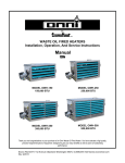
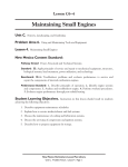
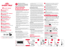
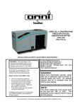
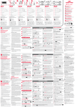
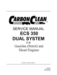
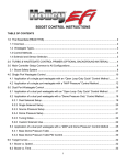
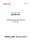
By
WASTE OIL FIRED HEATERS
Installation, Operation, And Service Instructions
Manual
MODEL OWH-150
150,000 BTU
MODEL OWH-250
250,000 BTU
MODEL OWH-350
350,000 BTU
MODEL OWH-500
500,000 BTU
Thank you and congratulations on your purchase of an Omni Waste Oil Fired Heater. You have selected a high quality,
precision-engineered piece of equipment, designed to give you many benefits as well as years of outstanding
performance.
Econo Heat♦5714 1st Avenue♦Spokane Washington 99212.♦(509)534-1022♦www.econoheat.com
100267 Rev A3
PRECAUTIONS
Waste oil may contain many foreign materials. Waste oil may also contain
gasoline. Therefore, specific precautions on the handling and storage of waste
oils are to be observed when using, cleaning and maintaining this heater. Use a
screen in a funnel when pouring oil into storage tank to catch foreign
material, i.e., gasket material and sealant fibers, etc. WARNING: This
appliance is not designated for use in hazardous atmospheres containing
flammable vapors or combustible dust, or atmospheres containing
chlorinated or halogenated hydrocarbons. Do not expose this unit to rain
or moisture. If installed in high moisture atmosphere, a special cover for
the integrated air compressor must be obtained from factory to avoid
rusting of internal raw metals. If this occurs, see trouble-shooting guide for
remedy. Uses only crank case oil, gear oil, hydraulic oils, auto trans. Fluid or #1
and #2 furnace oil. Do not use old, contaminated oils that have been stored in
underground tanks or outside barrels for long periods. Excessive water and
sludge may be present, causing quick filter plugging.
NOTES: The instructions contained in this manual apply to the installation,
operation, and service of Omni Waste oil fired heaters. The following instructions
should be carefully followed for obtaining the best possible installation, operation
and service conditions. Specifications are subject to change without notice. This
heater was designed to be a primary or auxiliary heat source, but not the only
source of heat. And provide economical disposal of waste oil. Proper operation
depends on the consistency of the oil. Any water or foreign material in the oil may
cause the unit to shut down. If a continuous stream of oil cannot be guaranteed
at the heater, the main heating system should be set above freezing which will
prevent any building damage if the waste oil heater were to become inoperative
during subfreezing weather, i.e. supply tank empty, filter plugged, etc.
UNCRATING: Immediately upon uncrating units, check rating plate for certainty
of electrical and mechanical characteristics. Also check the unit for any damage
that may have been incurred in shipment, if any damage is found, file a claim
with the transporting agency. The unit has been tested and inspected at the
factory prior to crating and was in perfect condition at that time. If anything is
missing check packing slip for indications of possible backorder of those parts or
components. Otherwise a claim must be filed for those missing parts.
2
Installation, Operation, And Service Instructions
IMPORTANT
NOTICE TO OWNER
AND INSTALLER
To enjoy the long term benefits of burning your used oil in an Omni Waste Oil Burning appliance,
it is necessary to become familiar with the correct installation operation and maintenance of your
new furnace. Before installing or operating this appliance, make sure you read and understand
this manual.
IMPROPER INSTALLATION OR LACK OF
MAINTENANCE
WILL VOID THE WARRANTY
The most critical sections of this manual are in order of importance as
follows:
•
•
•
•
Basic Operation Knowledge
Oil Suction Line Installation
Correct Draft Over Fire
General Maintenance Requirements
Identical to any gas or oil furnace, without adequate draft over the fire, the combustion
gases cannot escape the furnaces. The flame will lengthen resulting in an overheated
combustion chamber. Even if the heater is installed correctly and adequate draft achieved, a
flue passage blockage will affect the draft. Burning used oil is similar to burning wood. A fine gray
ash accumulates in the chamber and flue passage. This accumulation of ash will eventually affect
the draft. It is important to remove this ash before the draft is affected.
These topics are discussed in detail on the pages listed above. Please familiarize yourself with
these sections of your manual. Spending a few minutes to review this material will assure that
you receive the return on investment that you expect from your Omni heater.
Installation, Operation, And Service Instructions
3
SPECIFICATIONS
MODEL
BTU’S/HR INPUT
BTU’S/HR OUTPUT
GALLONS PER HOUR
VOLTAGE REQUIREMENTS
AMPS FULL LOAD with
Pump
FAN MOTOR HP
FAN MOTOR RPM
FAN DIA/PITCH
OWH-150
150,000
120,000
1.0
115
14.6
OWH-250
250,000
215,000
1.75
115
17.0
OWH-350
350,000
300,000
2.4
115
18.7
OWH-500
500,000
410,000
3.4
115
23.5
1/4
1075
18/36
1/3
1075
24/18
2 @ 1/4 each
1075
18/36
2 @ 1/3 each
1075
24/18
CFM (FREE AIR)
CFM W/ DUCTWORK at 100
FT
EFFECTIVE AIR FLOW
FLUE SIZE
WEIGHT W/ BURNER
SHIPPING WEIGHT
DIMENSIONS L/W/H
SHIPPING DIMENSIONS
L/W/H
3762
380
4466
2000
6275
1600
9001
3701
50 FT
8”
240 LBS
375 LBS
42-22-25 ½
64 ½-30-49
60 FT
8”
365 LBS
535 LBS
44-30-28 ½
64 ½-39-49
70 FT
8”
400 LBS
575 LBS
54-29 ½-28 ½
76-38-49
100 FT
10”
660 LBS
725 LBS
72-38-34 ½
92-44-50
Notes:
1.
2.
3.
4.
5.
6.
7.
All illustrations and specifications contained herein are based on the latest information
available at the time of publication approval. Econo Heat reserves the right to make
changes at any time without notice, in materials, specifications, and models or to
discontinue models.
These appliances are designed for commercial or industrial use only. Installation and use
of this waste-oil burning appliance shall be in accordance with the Standard for the
Installation of Oil Burning Equipment-ANS/NFPA 31-1987, and National Electric Code ANSI/NFPA 70-1990 and the requirements of the inspection authorities having jurisdiction.
Output depends on BTU content of oil used.
Atomizing Air Pressure for all fuels 10 P.S.I.
Furnace not to be used with air filters.
Intended maximum outlet air temp. 200 degrees F. (93 degrees C) or less.
Clearance from combustible materials on all models not to be less than:
TOP- 6”
REAR- 18”
BOTTOM- 18”
FRONT- 48”
SIDES- 18”
FLUE PIPE- 18”
Mounting Dimensions:
MODEL
4
A
B
OWH-150
35 ½”
20”
OWH-250
35 ½”
22 ¼”
OWH-350
47 ¾”
22 ¼”
OWH-500
63 ¼”
28 ¾”
Heater
(Top)
B
A
Installation, Operation, And Service Instructions
INSTALLATION PROCEDURES
Class A
Pipe
1
2' minimum higher than any
portion of a building within 10'
3' minimum above the
highest point where it
passes through the
roof of a building.
10'
Roof Jack
Supporting Thimble
Barometric
Damper
2
3
4
Heater
Thermostat
Circuit
Protection
Box
5
6
Oil Pump
With
Serviceable
Strainer Filter
Oil Supply
Tank
7
1
Class A Pipe, 8" or 10" stack depending on heater model (check local codes)
2
3
4 - 1/2" all thread hangers. Heater must be mounted level to allow standard
3% downward burner pitch into combustion chamber.
115vac 20amp power source. Wire and conduit per local codes.
4
Low voltage thermostat wire to "T" terminals of oil primary control on burner.
5
Oil suction line, 3/8" ID copper tubing.
6
Oil feed line, 3/8" ID to bulkhead connector on heater cabinet.
7
Suction line 6" minimum from bottom of supply tank to
prevent sludge from being introduced into the supply line.
Figure 1 – Installation Diagram
STACK INSTALLATION
1. (Optional) Install the supplied barometric damper in stack if draft up stack exceeds -.08. Draft
up stack must be -.04 to -.06 inches of water column. Check with draft meter between the top of
heater and damper. The over fire draft should be a minimum of -.02- check through flame
inspection port. Closing the damper door can increase draft.
Installation, Operation, And Service Instructions
5
2. For optional draft inducers or power vent wiring, See Figure 2. One of these devices must be
installed where back draft is present. In building or correct draft cannot be achieved.
OIL SUPPLY PIPING
1.
Use ONLY 3/8” nominal ID copper tubing with flare fittings only on the fuel suction from the tank
to the heater- Do NOT use ferrule fittings or Teflon tape on any pipe fittings.
2. Keep suction line approximately 6” from bottom of oil tank to prevent suction of sludge. Drain
accumulated sludge and water from tank periodically.
3. Use only an inside oil storage tank to supply heater. Do not draw from an outside tank,
especially not an underground tank, directly to heater. A separate transfer pump from an outside
tank with proper filtration to the inside supply tank is acceptable and available from Econo Heat.
4. The fuel supply pump included with heater is to be mounted at tank level or below.
(figure 1). This pump turns slowly requiring a number of minutes to accomplish purging ALL air, if
bubbles, skips, even slight pulsations in the oil flow from pumps bleeder port is unacceptable and
must be removed assuring proper oil flow to heater. Otherwise the flame sensor will not see
enough flame and heater will lockout. NOTE: PUMP ASSEMBLY MUST BE MOUNTED
HORIZONTAL.
5. Connect 3/8” oil supply line from the supply tank through the filter (figure 1) to the pump inlet
located same side as bleeder port. (figure 6) Continue oil supply line from pump outlet to bulk
head fitting secured to cabinet at left side of burner assembly (bulk head fitting has fuel flex hose
connecting it to burner).
WIRING
See Schematic diagram below and/or inside door of main electrical junction box on heater.
6
Installation, Operation, And Service Instructions
FUEL TRANSFER
PUMP
Fuse
Power Switch
THERMOCOUPLE
HIGH
VOLTAGE
TRANSFORMER
OIL
PREHEATER
BLOCK
L2
L1
WHT
BLK
CABINET
FAN
MOTOR
BLK
ORN
BLK
WHT
WHT
RED
BLU
YEL
BLOWER MOTOR
OIL PRIMARY CONTROL
(IE, Honeywell, etc.)
O
OPTIONAL
TIMER
RELAY
BLK
ORN
WHT
L1
BLK
WHT
Bi
METAL
HIGH
LIMIT
SWITCH
JUNCTION
BOX
BLK
WHT
BLK
YEL
WHT
BLK
BLU
RED
RED
WHT
WHT
GRN
WHT
RED
BURNER
DOOR
SAFETY
RECEPTICLE
WHT
500W
HEAT
ROD
AC POWER
INPUT
L2
PRI
L2
L1
HTR
BURNER
DOOR
SAFETY PLUG
(See Fuel Pump
Schematic Under
Pump Motor
Cover or User
Manual)
L1
WHT
YEL
OIL
PREHEATER BLOCK
CONTROLLER
RED
M
W
L2
HIGH LIMIT & FAN SWITCH
CABINET
THERMOSTAT
CONNECTION
OPTIONAL
DRAFT INDUCER
MOTOR
PHOTO EYE
FLAME SENSOR
BURNER
Figure 2 – Wiring Diagram
1. Wire 120V into main electrical box mounted on burner backside of heater cabinet with separate
circuit 20-amp protection using 12-gauge wire. Connect power line to black wire and all whites
(NUETRAL or COMMON) together. IMPORTANT, Connect ground wire to ground mounting point
in main junction box (green screw).
2. Connect wires from main junction box to remote oil pump power. Yellow to yellow and neutral
common white to white.
3. Wire low voltage thermostat into “T” marked terminals on oil primary control on burner. (Box on
burner gun assembly with red reset button). (figure 3).
DUCTING
All unit heaters are designed with a condenser-type pressure propeller fan for air deliver, and
have been successfully field ducted. (See Specifications) call factory for further assistance if
needed.
OIL BURNER
WARNING
Installation and use of this used oil burning appliance shall be in accordance with the
standard for the Installation of Oil Burning Equipment – ANSI/NFPA 31 – 1987, and
National Electric Code – ANSI/NFPA 70 – 1990 and the requirements of the inspection
authorities having jurisdiction.
Installation, Operation, And Service Instructions
7
Oil Primary
Control
Igniter
Transformer
Air Pressure
Adjuster
Air Band
(Combustion Air
Supply
Adjustment)
Air
Compressor
Run
Indicator
Power
Indicator
Oil Pressure
Gauge
Air Pressure
Gauge
Figure 3 – Oil Burner (Back View Closed)
Pre-Heater Control
Circuit Board
Oil Pre-Heater
Block
Air
Muffler/Filter
Photo Eye
Flame Sensor
Transformer
Igniter Springs
Electrical
Terminal Block
Heater
Electrical
Schematic
Figure 4 – Oil Burner (Back View Opened)
8
Installation, Operation, And Service Instructions
Electrodes
Oil Valve
Nozzle
Burner
Motor
Flame Cone
Figure 5 – Oil Burner (Front View)
Oil Outlet
Oil Inlet
Figure 6 –Oil Pump Diagram
Installation, Operation, And Service Instructions
9
Oil Pressure Gauge- Bench mark
indicator for proper flame length
adjustment and filter pump screen
or valve cleaning requirements
Cleanable Strainer Oil
Filter- removal of one
nut for screen access
Oil Primer Switch
Oil Shut-off ValveEliminates start
delays due to
possible drain
back
Inline Breaker
Adjustable Motor
Speed- Initial set up
only- Once set, no
adjustment needed
thereafter
Oil Flow Control Supply Pump has the ability
to control flame even when various viscosities
are used- furnace or stove oil to 90 weight
straight- flame remains stable
Figure 7 –Oil Pump Assembly
OIL BURNER TECHNOLOGY
Atomization Through Low Pressure
Preheat & Air Induction At Nozzle
Oil Preheater
Inside Burner
Suction Line
Pressure Line
Air Line to Preheater
Mixes with Oil at Nozzle
Air Compressor
On Burner
Oil Tank
Air Filter
Flow Control
Oil Pump
Internal Pump Filter
Filter
Omni’s patented burner technology improves the efficiency of the oil burn process by continuous
stabilization of the oil viscosity. Optimum atomization (spray) is accomplished by precisely preheating the oil and air prior to introduction to the combustion chamber. The waste oil enters into
the Oil Pre-Heater Block (figure 4) and is pre-heated to operating thermo setpoint, then
10
Installation, Operation, And Service Instructions
compressed air from the air compressor (figure 3) is mixed with the oil prior to spraying out the
nozzle similar to fuel injection, by breaking up the oil droplets into a finer mist or spray
(atomization). Electrodes mounted just above the nozzle (figure 5) provides continuous electrical
arc across electrode to electrode igniting the fine oil mist as it sprays out of the nozzle. Once
ignited the flame is forced into a swirl caused by the burners blower and specially designed flame
cone (figure 5) providing a very efficient and thorough burn of the waste oil.
Burner Components
•
Igniter Transformer: (figure 3) Supplies high voltage to the electrodes generating
electrical arc igniting the oil.
•
Oil Valve: (figure 5) energizes when burner is running and de-energizes when burner is
not running eliminating bleed back of oil out of the Pre-heater block.
•
Air Band: (figure 3) Adjusts amount of air introduced into the combustion chamber. Air
band is adjusted at the factory for optimum performance, approx. ½ to ¾ inch open. NO
FIELD ADJUSTMENT REQUIRED unless in high altitudes application where minor
adjustment may be required.
•
Oil Primary Control: (figure 3) Controls the oil burner ignition. Checks for flame in the
combustion chamber, if no flame is detected within 45 seconds, the oil primary will
shutdown the oil burner. To restart the unit, reset the red button on the oil primary.
•
Oil Pre-Heater Block: (figure 4) Pre-heats the oil and air before entering combustion
chamber.
•
Photo Eye: (figure 4) Senses flame in combustion chamber and signals oil primary when
no flame is present.
•
Igniter Springs: (figure 4) Transfers the high voltage from the igniter transformer to the
electrodes (when door is closed)
•
Air Pressure Gauge: (figure 3) Displays air pressure supplied by onboard air
compressor.
•
Air Compressor: (figure 3) Supplies air used within pre-heater block to aid in
atomization of the oil.
•
Air Muffler/Filter: (figure 4) Filters air and muffles the sound generated by the
compressor.
•
Pre-Heater Control Circuit Board: (figure 4) Precisely controls temperature of the Oil
Pre-Heater Block and controls safety feature of not allowing burner to energize until oil
has established operating thermo setpoint or shutdown burner if Pre-Heater Block
temperature falls below shutdown thermo setpoint.
•
Electrodes: (figure 5) Provides continuous high voltage electrical arc from electrode to
electrode igniting the waste oil as it is being sprayed out of the nozzle.
•
Nozzle: (figure 5) Low pressure nozzle for oil spray pattern.
•
Flame Cone: (figure 5) Specially engineered flame cone forces the flame into a swirl
pattern improving the burn thoroughness.
•
Burner Motor: (figure 5) Multitask motor turns the burner blower and integrated air
compressor.
•
Air Pressure Adjuster: (figure 3) Adjusts the air pressure going to the pre-heater block.
Should be adjusted between 12 PSI and 13PSI as indicated on the Air Pressure Gauge
on the burner for thorough burn of the waste oil.
Installation, Operation, And Service Instructions
11
Note: In order to insure proper air adjustment, air gauge must read 0 when burner
is cycled off or powered down.
•
Oil Pressure Gauge: (figure 3) Displays oil pressure at the burner. Adjust flame length
in the heater combustion chamber viewed through the inspection port located directly
above the burner gun assembly by increasing CW or decreasing CCW the adjuster
located on the oil delivery pump (figure7). The adjuster increases or decreases the pump
motors RPM which increases or decreases the delivery of fuel to the burner. When you
increase or decrease the fuel to the burner you will notice the flame length will increase
or decrease. Adjust flame length so flame is just slightly less than halfway down main
combustion chamber tube.
IMPORTANT:
Once adjusted for correct flame length, take note of oil gauge setting for bench mark
pressure reading needed when burning the specific fuel mixture generated by the owner.
PLEASE NOTE- Once flame is set the oil pressure gauge can read various pressures
when different viscosities of oils are used. The oil pressure gauge is an indicator of
where the PSI reading will be when that oil viscosity is being burned. The oil gauge is
used for servicing diagnostics assistance.
12
•
Power Indicator: (figure 3) Indicates when power is present at the burner.
•
Run Indicator: (figure 3) Indicates that the burner is ready for operation after the initial
pre-heat time of approx. 5 minutes from initial power up.
Installation, Operation, And Service Instructions
INITIAL START PROCEDURE
1. IMPORTANT- Prior to starting the unit, pre-fill the filter and fuel line with oil to assist priming
procedure. Oil pump motor turns at low RPM’s and would take significant time to complete
priming process if not pre-filled. Make sure the oil supply line fittings are air tight. Vacuum
leaks are notoriously hard to find. Pressurizing the line with oil in it can help to locate leaks.
2. Proper draft. Draft is the gasses traveling through the heater and out the stack or flue. If
exhaust fans are present in your building, chances are a draft inducer will be needed. Call our
factory or see our website for help, www.econoheat.com
3. During the initial power up process the burner is locked out from energizing until the oil has
been properly pre-heated to operating thermo setpoint, approx 3 to 5 minute duration. Once
the oil has been pre-heated, power is then applied to burner componenets and oil pump.
4. Making sure the thermostat is turned off, apply power to the burner. Switch burner main
power switch to ON position. After allowing the oil pre-heater time to establish temperature
setpoint, approximately 5 minutes. Jump the “T” terminals on the Oil Primary Control (figure
3). Once the burner is running, temporarily jump the “F” terminals on the Oil Primary. This
will allow the burner to run during the pump priming process.
5. Priming the oil pump: Open bleeder valve one turn until all air is expelled (figure 6). This
may need to be done twice to insure all air is removed. IMPORTANT: When fully purged and
flame is established remove temporarily jumpers on “F” terminals of the Oil Primary to allow
safety features of the unit to operate properly.
6. Adjust air supply of integrated air compressor to 8-12 P.S.I. This is factory preset, however,
due to freight handling settings may be compromised.
7. Combustion air band (figure 3) should be open approximately 1/2” or until flame is clear
yellow, not orange. Opening the air band too far may cause delayed in starting or even
prevent the flame from starting.
8. Inspect flame length through inspection door located above burner gun assembly. End of
flame should reach no further than ½ way down combustion tube. To accomplish this flame
length, use adjustment knob on opposite side of oil pump. NEVER ATTEMPT TO START
HEATER WHEN COMBUSTION CHAMBER IS HOT AND A DELAYED START OCCURS.
MAINTENANCE SCHEDULE
WEEKLY
--- Drain water from storage tank.
MONTHLY
--- clean stainless filter screen in filter periodically and drain off any water accumulation (figure
14). Monitor : every application is different and may vary depending on contamination of oils
being used.
ONCE EACH SEASON
(OR MORE DEPENDING UPON USAGE OR CONTAMINATION OF OIL).
--- Swing out burner assembly door and clean flame cone. (figure 5 and figure 8).
--- Remove combustion chamber & heat exchanger clean out panels at same side of lift out door
panel on heater and vacuum out the accumulated ash & soot. (figure 12).
--- Clean pump strainer. Remove pump cover for access. (figure 13). CAUTION!-Be careful of
gasket.
--- Clean air compressor filter element.
Installation, Operation, And Service Instructions
13
YEARLY
--- Clean flue pipe stack-to loosen soot remove stack at top of heater and tap thoroughly. Then
vacuum upper exchanger.
--- Inspect electrode adjustment. (figure 10). Due to erosion, adjustment may change.
--- Replace nozzle every 3-5 years depending on usage (figure 5, 9, 11). Will lose efficiency due
to erosion. This can be accessed by swinging burner door open. (figure 8)
---IMPORTANT: TO TURN POWER OFF, Remove electrical plug from heater cabinet to burner.
Remove 9/16” burner door securing nut, swing open burner door. Remove nozzle with 5/8”
socket. (figure 8, 9)
ELECTRODE ADJUSTMENTS
Electrodes are adjusted at time of manufacture. However, they should be check periodically and
at time of installation to be sure they are set as noted in the following dimensional drawing. Swing
burner door back for inspection. (figure 5, 10, 11)
CAUTION: TURN OFF MAIN ELECTRIC SUPPLY SWITCH BEFORE CHECKING OR
ADJUSTING ELECTRODE SETTING.
NOZZLE POSITION IN RELATION TO ENDCONE/BURNER TUBE
Tip of nozzle must be ¼” ahead of inside radius of end-cone. If nozzle is behind inside radius of
end-cone, coking will occur and end cone can become clogged. (figure 10). IMPORTANT NOTE:
be sure nozzle is centered, if nozzle is higher than center, press nozzle down to bottom out preheater stand.
To adjust, open burner door (figure 8), loosen Preheat Sink securing nut and set screw, push fore
or aft as needed. WARNING: This adjustment is done at the factory and should not be moved
unless Fig 8 dimensions have been altered.
When cleaning, inspect all three
pieces thoroughly. When
disassembling and reassembling
nozzle, keep facing up as shown.
Figure 8 – Burner Door View
14
Figure 9 – Nozzle Assembly Detail
Installation, Operation, And Service Instructions
Figure 10 – Electrode Adjustment Detail
Electrodes
Nozzle
Pre-Heater
Control Card
Thermocouple
Figure 11 – Pre-Heater Block Detail (Removed From Burner for Clarity)
Figure 12 – Combustion Chamber and Heat Exchanger Cleanout Door, Models OWH 250, 350, 500
Installation, Operation, And Service Instructions
15
Remove 4 bolts for
access to strainer.
CAUTION must be
taken not to destroy
gasket during
removal of housing
Tabs
Strainer must be installed with tabs in
direction shown
Figure 13 – Pump Strainer
Washer
Nut
Bolt
Filter Housing
Filter Housing
Stainless Filter Screen
Figure 14 – Oil Filter
16
Installation, Operation, And Service Instructions
TROUBLE SHOOTING
♦Most Likely
Symptom
1. Heater shuts off
2. Loss of prime overnight
•Less Likely
Cause
♣Least Likely
Remedy
♦Manual reset
♦Requiring manual restart by reset button on.
♦Vacuum air leak in fuel line
♦Check all fuel connections. Tighten fittings.
Won’t hold vacuum
♣Plugged pump screen
♣ Check pump screen, may need cleaning-to access, remove pump
IS TANK EMPTY?
• Plugged filter or tank oil empty
• Clean filter. Using vent port, reprime pump (See Figure 6 & 7).
♦Vacuum Leak
♦Open bleeder port if air present. Check and tighten fittings.
♦Inadequate Fuel Supply
♦Clean filter. Check all fuel connections. Tighten fittings.
• No Pressure
• Check, may need cleaning—to access, remove pump cover.
cover
3. Fails to start.
• Using vent port, reprime pump (See Figure 6 & 7)
•No Pre-heat
• Be sure all wiring to pre-heater is tight-no loose connections.
•Auto start circuit not functioning
• Check circuit control board and replace if necessary.(Call Factory)
• Bad firerod-Replace. Continuity at terminals.
• Check continuity at terminals of firerod limit snap switch.
•No Arc
Replace if needed.
• Check springs to electrode rod adjustment (under transformer)
make sure they make good contact. Open burner door and make
sure electrode tips aren’t touching flame cone. Readjust.
•No Air Pressure
• Check pressure regulator and adjust. Check air supply line for
restrictions or leaks. Pull compressor cover and inspect carbon
vanes. May need to replace. Check filter, clean if needed.
4. Reduced air pressure,
cannot increase.
♦Gauge may be bad.
♦Replace gauge.
♦Intake filter muffler is plugged
♦ Remove & Clean with carburetor cleaner,
♣Compressor vanes may be worn.
♣ Replace carbon canes.
with dust or dirt.
• Exposed to water.
5. Hard starting diminished
flame.
dry thoroughly. Do Not Use.
• Remove cover, clean rust with emery cloth.
♦Partially plugged filter.
♦Clean filter. Using vent port-reprime pump (See Figure 6 & 7)
♣Out of fuel
♣Refill Storage.
♣No oil to burner
♣Clean pump screen-Remove pump cover. Using vent
•Restriction in nozzle usually only
•Remove nozzle and check for foreign objects. (See Figure 9 and 11)
•Aluminum Block Pre-heater inside burner should not build
port, reprime pump. (See figure 6 & 7)
when initially installed. New lines
may have foreign material in them.
up carbon. If carbon is present, pre-heat circuit is
malfunctioning. Thermocouple heat sensor wire could
have open circuit. Heat control board may have blown
circuit and circuit board fuse. Inspect both and replace
either if needed. (See Figure 11).
•Air band open too far
•Close air band—while viewing flame; open air band
♦Heater over firing.
♦Investigate and locate reason for over firing. I.e., nozzle
slowly until combustion chamber is clear, not orange.
6. Heater cycles frequently,
without thermostat
eroded, pump not functioning properly, decrease pump motor
speed.
temperature setting being
achieved in area to be
heated.
♣Temperature setting wrong
On high limit fan safety switch.
•High limit safety switch bad
Installation, Operation, And Service Instructions
(See #6 for remedy)
♣Check temperature setting and adjust as necessary.
• Replace high limit fan safety switch.
17
7. Heater rumbles and
♦Pump setting wrong
excessive heat blow back
♦Pump not functioning properly-over firing. May need RPM
readjust. Reset flame slightly less than ½ way down tube
from flame vision port.
combustion chamber. Use adjustment knob on pump motor.
(See Figure 7).
♣Draft incorrect. If proper draft
can’t be achieved, heater could
♣Set draft. Clean out combustion chamber and exchangers
of ash. Check draft-reset if needed.
have excessive amount of ash and
wont allow sufficient draft.
8. Heater establishes flame
but locks out or shuts off.
Need to reset primary.
9. Proper draft setting
cannot be achieved
♦Photo eye cant see flame.
♦Clean photo eye which is smoked up by back draft smoke.
♣Due to back draft. Flame end
♣Swing open burner door and clean ash build up from flame
cone may have ash.
end cone. (See Figure 5 & 8).
•Flame too small
•Increase pump motor speed (See Figure 7).
♦Negative draft in building
♦ May need to install power vent/draft inducer’s in stack.
♣ Excessive ash buildup/Heater
♣ Clean ash and soot from combustion chamber and heat
or exhaust fans present.
(See Figure 2 for wiring).
exchangers.
10. Poor or reduced heat
production.
♦Flame too small
♣Entire fuel supply may be plugged.
•Excessive ash buildup exchangers
•Through vision port, check flame
to see if flame is smaller than usual.
18
♦Nozzle may be plugged with debris-usually after filter is cleaned.
♣Clean filter both, oil strainer and oil pump screen.
•Clean ash from combustion chamber and exchangers.
•May need to readjust pump RPM. (Use knob on pump motor).
(See Figure 7).
Installation, Operation, And Service Instructions
Omni Unit Heaters 150, 250, 350, 500
Limited Warranty
Econo Heat (manufacturer) warrants to the purchaser of Unit Heaters listed above will be free
from defects in materials and workmanship for the durations specified below, which duration
begins on the date of delivery to the customer. Customer is responsible for maintaining proof of
date of delivery.
If return is deemed necessary for warranty evaluation and determination of repair or replacement,
unit heater is to be sent to the factory with freight prepaid. Econo Heat reserves the right to
determine appropriate action for repair or replacement.
No parts will be accepted by Econo Heat without RA# (return authorization number) clearly marked on outside of shipping package. Obtaining RA#
requires model and serial numbers, description of part being replaced and nature of defect. Call factory to receive RA#.
Warranty Covers:
1.
2.
3.
4.
Combustion Chamber and Heat Exchanger full Twelve (12) years limited. *full repair or
replacement, (Parts Only)
Oil Heater Block, twenty (20) years. (Part Only)
Oil Heater Block Controller PCB, three (3) years. (Part Only)
All other components, one (1) year. (Parts Only)
This warranty is void if:
1. Warranty registration card is not returned within thirty (30) days of purchase.
2. Any part or component subject to abuse or altered from original manufactures specifications.
3. Installation not in accordance with instructions.
4. Has not been properly maintained, operated or has been misused.
5. Wiring not in accordance with diagram furnished with unit heater.
6. Unit heater is operated in the presence of chlorinated vapors.
7. Air through unit heater is not in accordance with rating plate and specifications.
Warranty is limited to the original purchaser.
The above warranty is in lieu of all other warranties expressed or implied. Econo Heat does not authorize
any person or representative to make or assume any other obligation or liability that is not in accordance
with above warranty. Econo Heat is not responsible for any labor cost unless prior authorization in
writing has been obtained.
NOTE: Combustion Chamber Warranty is specific to material and workmanship. Workmanship means
Econo Heat warranties the welds are good and will hold. Material means they won’t corrode through due to
sulfur in the ash that accumulates during operation. Warranty does not apply to units that experience
overheating stress cracks. These are not incurred because the materials are inadequate for the application
nor are they a result of a weld breaking lose because of bad penetration, which is easily recognized by the
metal left beneath the weld. These cracks occur as a direct result of (1)improper draft, either by inadequate
initial installation and setup which requires (a) establishing a proper draft during installation (b) back draft
has occurred due to ash buildup, backing up hot gas passageways either in the exchangers, the stack, or
both. (2) Over firing by setting oil supply pressure too high (see manual for proper setting) these are all
cases of thermal overload.
* Under normal use only. If misuse or abuse is deemed apparent after inspection, warranty is void.
Installation, Operation, And Service Instructions
19
20
Installation, Operation, And Service Instructions
WARRANTY CARD
Please fill our, tear off and return to manufacturer
Return following warranty information to manufacturer within thirty (30) days of purchase or warranty will not be valid. (Please print or type).
Date of Purchase_____________________________________________________________________
Serial #__________________________ Model ____________________________________________
Customer Name_____________________________________________________________________
Address____________________________________________________________________________
City _________________________ State ________________ Zip Code ________________________
Dealer ____________________________________________________________________________
Address ___________________________________________________________________________
City_________________________ State _________________ Zip Code _______________________
Installed at ________________________________________________________________________
Installation Checklist
Installation, Operation, And Service Instructions
21