1
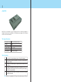
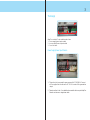
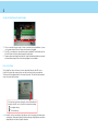
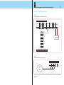
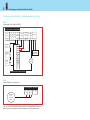
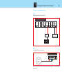
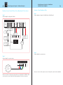
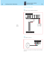
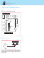
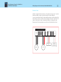
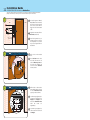
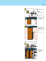
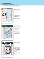
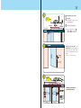
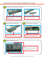
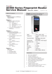
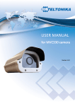
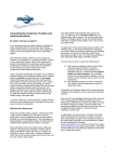
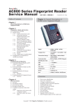
User Manual
ENGLISH
2
ADAPTEC
AdapTec is a combination of a power supply and a door controller packaged in a
compact box to ease on installation, to provide power supply and to enhance
access control functionalities.
The Specifications
Dimension (mm)
Weight
Input Voltage
Output Voltage
EM Output
Siren Output
198 (L) x 131 (W) x 43 (H)
920g
AC 110 / 240 V (universal input)
DC 12V 3A
DC 12V 3A
Max 0.5A, NC type
The Functions
1
To power on the time attendance system of FingerTec® readers.
2
To link door accessories including EM Lock and Drop Bolt with the
FingerTec® reader.
3
To control In-Out reader system; a system where two readers control
one entrance.
4
To support rechargeable backup battery (compatible with any 12V
rechargeable backup battery) and to act as a backup power supply
in the event of power failure.
5
To integrate with siren feature of the reader to alert user when reader
is illegally dismantled.
Note: AdapTec is compatible with NC type of siren with maximum 0.5A load.
3
The Design
33
11
2
2
AdapTec consists of 2 main modules and a timer:
1. Power supply/power input module
2. Access control/power output module
3. Door lock timer
Power Supply/Power Input Module
11
2
1. This portion is to be connected to power source with AC 110/240V. AC current
will be supplied into this side and a DC 12V 2A current will be generated as
output.
2. These two cables, -V and +V are default and connected to the inner part of AdapTec.
Please do not remove or change these cables.
4
Access Control/Power Output Module
1
22
33
1. This is connected to push button if siren is installed during installation. A press
on the push button will turn off siren when the siren is triggered.
2. The LED is an indicator to show that the output is available. Please return the unit
if the LED does not light up after the reader is switched on.
3. These are the power outputs from AdapTec. FingerTec® readers and door accessories
will need these outputs. Refer to the wiring diagram for more details.
Door Lock Timer
This is AdapTec’s door lock timer. User can adjust the timing for the EM Lock or
Drop Bolt to close after opening. User can turn the timer by using a screwdriver.
The time will be lengthened when it is turned clockwise. The time will be shortened
when it is turned anti-clockwise.
This is a door lock timer of AdapTec. User could adjust the
timing for the EM Lock or Drop Bolt to close after opening.
Lengthen timing
Shorten timing
Note: AdapTec can be connected to other devices, which are having the same power
consumption. Please seek FingerTec®’s advice through [email protected] before
using AdapTec with other FingerTec® models.
5
Wiring Diagrams for FingerTec® AC900 with AdapTec
Function: Time Attendance Only
Step 1
Connect AdapTec to FingerTec® AC900
Siren
Accept
0
Relay
Access Control/Power Output Module
Siren
Output
12V EM
OK 12V MAX 0.5A
0
0
12V
Output
Voltage
Tamper
Switch
Input
EXT. Door To Battery
I/P
Exit
0
C
12V
12V
NC
0
-
+
GND
PWR
COM
DC 12V
Rechargeable
Backup Battery
NO
NC
GND
AL+
ALBUT
GND
B+
B-
Connection Points in FingerTec® AC900
Step 2
Connect AdapTec to a power source
Power Supply/Power Input Module
L
N
E
-V
+V
AC110/240V
L - Live
N - Neutral
E - Earth
Now you can turn on the power source and using the system for time attendance
purpose only.
6
Wiring Diagrams for FingerTec® AC900 with AdapTec
Function: Access Control Only or Time Attendance & Door Access
Step 1
Connect AdapTec to FingerTec® AC900
Siren
Accept
0
Relay
Access Control/Power Output Module
Siren
Accept
12V EM
MAX
0.5A
OK 12V
0
EM
Lock
0
+
-
12V
Output
Voltage
0
12V
Tamper
Switch
Input
C
NC
EXT. Door
To Battery
Exit
I/P
12V
0
-
+
GND
PWR
COM
Emergency
Break Glass
(NC)
DC 12V
Rechargeable
Backup Battery
NO
2
NC
3
GND
AL+
AL-
ON-OFF
Key Switch
(NC)
C
BUT
D
GND
Push
Button
B+
BConnection Points in FingerTec® AC900
Step 2
Connect AdapTec to a power source
Power Supply/Power Input Module
L
N
E
-V
+V
AC110/240V
L - Live
N - Neutral
E - Earth
Now you can turn on the power source and start to use FingerTec® AC900 for door
access control or Access Control Only/Time Attendance & Door Access functions.
7
Wiring Diagrams for FingerTec® AC800 with AdapTec
Function: Time Attendance Only
Step 1
Connect AdapTec to FingerTec® AC800
Siren
Accept
0
Relay
Access Control/Power Output Module
Siren
Output
12V EM
OK 12V MAX 0.5A
0
0
12V
Output
Voltage
Tamper
Switch
Input
EXT. Door To Battery
I/P
Exit
0
C
12V
12V
NC
0
-
+
DC 12V
Rechargeable
Backup Battery
AC800 I/O
Controller
FingerTec®
AC800
fingerprint reader
Step 2
Connect AdapTec to a power source
Power Supply/Power Input Module
L
N
E
-V
+V
AC110/240V
L - Live
N - Neutral
E - Earth
Now you can turn on the power source and using the system for time attendance
purpose only.
8
Wiring Diagrams for FingerTec® AC800 Plus &
AC800 Plus MC with AdapTec
Wiring Diagrams for FingerTec® AC800 with AdapTec
Function: Access Control Only or Time Attendance & Door Access
9
Function: Time Attendance Only
Step 1
Step 1
Connect AdapTec to FingerTec® AC800 Plus & AC800 Plus MC
Connect AdapTec to FingerTec® AC800
Siren
Accept
0
Relay
Access Control/Power Output Module
Siren
Accept
12V EM
OK 12V MAX 0.5A
0
EM
Lock
0
Tamper
Switch
Input
Output
Voltage
12V
0
12V
C
NC
EXT. Door
To Battery
Exit
I/P
12V
0
-
+
+
AC800 I/O
Controller
Emergency
Break Glass
(NC)
2
ON-OFF
Key Switch
(NC)
C
NO
COM
NC
PUSH
DC 12V
Rechargeable
Backup Battery
GND
3
FingerTec®
AC800
fingerprint reader
Push
Button
D
Connection Points in FingerTec® AC800 Plus
Step 2
Connect AdapTec to a power source
Step 2
Connect AdapTec to a power source
Power Supply/Power Input Module
L
N
E
-V
+V
AC110/240V
L - Live
N - Neutral
E - Earth
Now you can turn on the power source and using the system for time attendance
Now you can turn on the power source and start to use FingerTec® AC800 for door
access control or Access Control Only/Time Attendance & Door Access functions.
9
Function: Time Attendance Only
Step 1
Connect AdapTec to FingerTec® AC800 Plus & AC800 Plus MC
Access Control/Power Output Module
Siren
Accept
0
Relay
8
Wiring Diagrams for FingerTec® AC800 Plus &
AC800 Plus MC with AdapTec
Wiring Diagrams for FingerTec® AC800 with AdapTec
Siren
Output
12V EM
OK 12V MAX 0.5A
0
0
12V
Output
Voltage
Tamper
Switch
Input
EXT. Door To Battery
I/P
Exit
0
C
12V
12V
NC
0
-
+
PWR
GND
SEN
DC 12V
Rechargeable
Backup Battery
GND
DC 12V
Rechargeable
Backup Battery
BUT
NO
COM
NC
AL+
AL-
Connection Points in FingerTec® AC800 Plus
Step 2
Connect AdapTec to a power source
Power Supply/Power Input Module
L
N
E
-V
+V
AC110/240V
L - Live
N - Neutral
E - Earth
Now you can turn on the power source and using the system for time attendance
purpose only.
Wiring Diagrams for FingerTec® AC800 Plus &
AC800 Plus MC with AdapTec
10
Function: Access Control Only or Time Attendance & Door Access
Step 1
Connect AdapTec to FingerTec® AC800 Plus & AC800 Plus MC
Siren
Accept
0
Relay
Access Control/Power Output Module
Siren
Accept
12V EM
MAX
0.5A
OK 12V
0
EM
Lock
0
+
-
12V
Output
Voltage
0
12V
Tamper
Switch
Input
NC
C
EXT. Door
To Battery
Exit
I/P
12V
0
-
+
PWR
GND
SEN
Emergency
Break Glass
(NC)
DC 12V
Rechargeable
Backup Battery
GND
2
3
BUT
NO
COM
NC
ON-OFF
Key Switch
(NC)
C
AL+
D
AL-
Push
Button
Connection Points in FingerTec® AC800 Plus
Step 2
Connect AdapTec to a power source
Power Supply/Power Input Module
L
N
E
-V
+V
AC110/240V
L - Live
N - Neutral
E - Earth
Now you can turn on the power source and start to use FingerTec® AC800 Plus or
AC800 Plus MC for door access control or Access Control Only/Time Attendance &
Door Access functions.
11
Wiring Diagrams for Siren Function (AC900/AC800/AC800 Plus)
Function: Siren
AdapTec is equipped with siren function, a NC (normally close) type siren. To use this
function you need to connect a sensor from FingerTec® reader to AdapTec.
Locate a sensor inside the FingerTec® reader and the other piece on the back plate. Both
sensors must be close to each other. Siren will trigger if the sensor is apart from one
another. If the FingerTec® reader is dismantled, the AdapTec will trigger the alarm.
Please press the Siren Accept button to turn off the siren. Find the details as below:
Access Control/Power Output Module
Siren
Accept
0
0
Relay
Wiring Diagrams for FingerTec® AC800 Plus &
AC800 Plus MC with AdapTec
Siren
Accept
12V EM
MAX
0.5A
OK 12V
0
12V
Output
Voltage
0
12V
Tamper
Switch
Input
C
NC
EXT. Door
To Battery
Exit
I/P
12V
Magnetic Switch
Sensor
Push
Button
Siren
0.5A
0
-
+
DC 12V
Rechargeable
Backup Battery
Installation Guide
12 AC900/AC800/AC800 Plus Series on Wooden Door
(The door accessories mentioned in this chapter are not included in the FingerTec® AC900/AC800/AC800 Plus
package. Please consult your vendor or you can source for these items from your local market.)
STEP
1
1 To install FingerTec® AC900/
WOODEN DOOR
WALL
AC800/AC800 Plus on the wall,
drill 5 holes as shown. 4 small
holes are for screws and the
bigger hole is for the network
cable.
WALL
1
2
Back Steel
Plate
2 Tighten the 4 screws to fix the
Screws
Back Plate on the wall.
4 feet / 1.2 meter
(recommended)
3
3 Install the keyswitch as per
instructions given in the box.
The keyswitch is an override
key in case of system failure or
breakdown.
OUTDOOR
STEP
2
CEILING
1
Drill 3 holes on the wooden
door.
2
Place Steel Bar on the door.
Insert the Silver Nut on one
side and Allen Key Screw on
the other side. Tighten the
screw to lock the Steel Bar
onto its position.
1
Drill 4 holes on the wooden
frame. Tighten the 4 screws to
fix the Aluminum Plate
properly on the doorframe.
2
Use Allen Key to tighten the 2
screws at the bottom of the
Magnet. The Magnet will
stick to the Aluminum Plate
when the screws are
tightened up.
3
Use Allen Key to tighten the
other 2 screws on the sides of
the Magnet.
1
2
Silver
Nut
Steel
Bar
2
Allen Key
Screw
Wooden Doorframe
INDOOR
STEP
3
CEILING
Doorframe
Screws
Magnet
Aluminum
Plate
1
Allen
Key
Screws
2
3
INDOOR
13
STEP
4
2
AC110/240V
Power
Input
3
To FingerTec®
AC900 Series
1
1
Computer/
Network Hub/
Network Switch
ABOVE CEILING
BELOW
CEILING
5
12V 3A DC Power Output
2
AdapTec
(Note: Refer to page 5-11 for
wiring diagrams.)
3
12V Rechargeable Battery
Note: It is recommended to place 1 ,
2 and 3 out of sight, either
above the ceiling or wall-mounted.
CEILING
STEP
1
CEILING
Emergency Break Glass and
Push Button should be installed
indoor. These two items are for
user to open the door from the
inside.
Emergency
Break Glass
Note: Please conceal the wiring.
Push Button
4 feet / 1.2 meter
(recommended)
INDOOR
STEP
6
AdapTec
AC110/240V
Power
Input
12V Rechargeable
battery
To FingerTec® AC900 Series
ABOVE CEILING
CEILING
Hub / Switch
Emergency
Break Glass
PC
FingerTec®
AC900
Series
Push Button
ON-OFF
Keyswitch
OUTDOOR
INDOOR
NETWORKING
OVERVIEW OF THE WHOLE
SYSTEM INSTALLATION
Guide
AC900/AC800/AC800 Plus Series on Glass Door
14 Installation
(The door accessories mentioned in this chapter are not included in the FingerTec® AC900/AC800/AC800 Plus
package. Please consult your vendor or you can source for these items from your local market.)
STEP
1
1 To install FingerTec® AC900/
GLASS DOOR
WALL
AC800/AC800 Plus on the wall,
drill 5 holes as shown. 4 small
holes are for screws and the
bigger hole is for the network
cable.
WALL
1
2
Back Steel
Plate
2 Tighten the 4 screws to fix the
Screws
Back Plate on the wall.
4 feet / 1.2 meter
(recommended)
3
3 Install the keyswitch as per
instructions given in the box.
The keyswitch is an override
key in case of system failure or
breakdown.
OUTDOOR
STEP
2
CEILING
1
Lodge the U-Bracket into the
upper edge of the glass
doorframe. Tighten the 4
Allen Screws to hold the
U-Bracket into position.
2
Place the Steel Bar on the
side of the U-Bracket. Tighten
the Philip Screw to lock the
Steel Bar onto position.
1
Drill 4 holes on the doorframe.
Tighten the 4 screws to fix the
Aluminum Plate properly on
the doorframe.
2
Use Allen Key to tighten the 2
screws at the bottom of the
Magnet. The Magnet will
stick to the Aluminum Plate
when the screws are
tightened up.
3
Use Allen Key to tighten the
other 2 screws on the sides of
the Magnet.
U-Bracket
1
Allen Key
Screws
Steel
Bar
1
Allen Key
Screws
2
Philip Screw
Glass Doorframe
OUTDOOR
STEP
3
CEILING
Doorframe
Screws
Magnet
Aluminum
Plate
1
Allen
Key
Screws
2
3
OUTDOOR
15
STEP
4
2
AC110/240V
Power
Input
3
To FingerTec®
AC900 Series
1
1
Computer/
Network Hub/
Network Switch
ABOVE CEILING
BELOW
CEILING
5
12V 3A DC Power Output
2
AdapTec
(Note: Refer to page 5-11 for
wiring diagrams.)
3
12V Rechargeable Battery
Note: It is recommended to place 1 ,
2 and 3 out of sight, either
above the ceiling or wall-mounted.
CEILING
STEP
1
CEILING
Emergency Break Glass and
Push Button should be installed
indoor. These two items are for
user to open the door from the
inside.
Emergency
Break Glass
Note: Please conceal the wiring.
Push Button
4 feet / 1.2 meter
(recommended)
INDOOR
STEP
6
AdapTec
AC110/240V
Power
Input
12V Rechargeable
battery
To FingerTec® AC900 Series
ABOVE CEILING
CEILING
Hub / Switch
FingerTec®
AC900
Series
Emergency
Break Glass
Push Button
PC
ON-OFF
Key Switch
OUTDOOR
INDOOR
NETWORKING
OVERVIEW OF THE WHOLE
SYSTEM INSTALLATION
Instructions on how to mount an AdapTec onto a wall
STEP
1
Remove the L-shape piece from the AdapTec
Find an L-shape piece at the top right of
an AdapTec. This piece is attached to the
AdapTec by 2 screws.
STEP
2
After removing the piece, you will have
one L-shape piece and 2 screws.
STEP
Install the piece to the AdapTec
Attach the L-shape to the AdapTec as
shown and tighten the screws.
3
The other 2 holes at the bottom
Open the cap, look for the part shown in
the diagram and you will see 2 holes.
STEP
4
Mount the AdapTec on a wall
Identify a location to mount the AdapTec
on a wall.
Fix the AdapTec onto the wall by tighten
the screws into the 4 holes.
© 2006 FingerTec Worldwide Ltd. All rights reser ved.