1
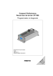
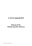
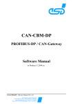
CAN-CBM-SIO1
CAN-CBM-SIO4
CAN - RS-232, RS-422,
RS-485 or TTY-Interface
CAN-CBM-PLC/331-1
Automation Computer
with CAN-Interface
Hardware Manual
CAN-CBM-SIO1 / CAN-CBM-SIO4 / CAN-CBM-PLC/331-1 Hardware Rev. 2.0
NOTE
The information in this document has been carefully checked and is believed to be entirely reliable. esd
makes no warranty of any kind with regard to the material in this document, and assumes no
responsibility for any errors that may appear in this document. esd reserves the right to make changes
without notice to this, or any of its products, to improve reliability, performance or design.
esd assumes no responsibility for the use of any circuitry other than circuitry which is part of a product
of esd gmbh.
esd does not convey to the purchaser of the product described herein any license under the patent rights
of esd gmbh nor the rights of others.
esd electronic system design gmbh
Vahrenwalder Str. 205
30165 Hannover
Germany
Phone:
Fax:
E-mail:
Internet:
+49-511-372 98-0
+49-511-372 98-68
[email protected]
www.esd-electronics.com
USA / Canada
7667 W. Sample Road
Suite 127
Coral Springs, FL 33065
USA
Phone:
Fax:
E-mail:
+1-800-504-9856
+1-800-288-8235
[email protected]
CAN-CBM-SIO1 / CAN-CBM-SIO4 / CAN-CBM-PLC/331-1 Hardware Rev. 2.0
Document file:
I:\texte\Doku\MANUALS\CAN\Cbm\SIO-331\Englisch\CSIO-20H.en6
Date of print:
18.07.2000
PCB version:
CPU331 Rev. 1.1
SIO3311 Rev. 1.1
SIO4 Rev. 1.0
Changes in the chapters
The changes in the user’s manual listed below affect changes in the hardware as well as changes in the
description of the facts only.
Chapter
Changes versus previous version
-
Description of CAN-CBM-SIO4 module and CAN-CBM-PLC/331-1 module
inserted
-
-
Technical details are subject to change without notice.
CAN-CBM-SIO1 / CAN-CBM-SIO4 / CAN-CBM-PLC/331-1 Hardware Rev. 2.0
CAN-CBM-SIO1 / CAN-CBM-SIO4 / CAN-CBM-PLC/331-1 Hardware Rev. 2.0
Contents
Page
1. Overview . . . . . . . . . . . . . . . . . . . . . . . . . . . . . . . . . . . . . . . . . . . . . . . . . . . . . . . . . . . . . . . . . . . . 3
1.1 Description of the Module . . . . . . . . . . . . . . . . . . . . . . . . . . . . . . . . . . . . . . . . . . . . . . . . 3
1.2 Front View with Connectors and Coding Switches . . . . . . . . . . . . . . . . . . . . . . . . . . . . 5
1.2.1 CAN-CBM-SIO1 and CAN-CBM-PLC/331-1 . . . . . . . . . . . . . . . . . . . . . . . . . 5
1.2.2 CAN-CBM-SIO4 . . . . . . . . . . . . . . . . . . . . . . . . . . . . . . . . . . . . . . . . . . . . . . . 5
1.3 Summary of Technical Data . . . . . . . . . . . . . . . . . . . . . . . . . . . . . . . . . . . . . . . . . . . . . . 6
1.3.1 General Technical Data . . . . . . . . . . . . . . . . . . . . . . . . . . . . . . . . . . . . . . . . . . . 6
1.3.2 Micro Controller Unit . . . . . . . . . . . . . . . . . . . . . . . . . . . . . . . . . . . . . . . . . . . 7
1.3.3 CAN/DeviceNet Interface . . . . . . . . . . . . . . . . . . . . . . . . . . . . . . . . . . . . . . . . 7
1.3.4 Serial Interface . . . . . . . . . . . . . . . . . . . . . . . . . . . . . . . . . . . . . . . . . . . . . . . . . 8
1.4 Software Support . . . . . . . . . . . . . . . . . . . . . . . . . . . . . . . . . . . . . . . . . . . . . . . . . . . . . . 8
1.4.1 CAN-CBM-SIO1 / CAN-CBM-SIO4 . . . . . . . . . . . . . . . . . . . . . . . . . . . . . . . . 8
1.4.2 CAN-CBM-PLC/331-1 . . . . . . . . . . . . . . . . . . . . . . . . . . . . . . . . . . . . . . . . . . . 8
1.5 Order Information . . . . . . . . . . . . . . . . . . . . . . . . . . . . . . . . . . . . . . . . . . . . . . . . . . . . . . 9
1.5.1 CAN-CBM-SIO1 / CAN-CBM-SIO4 . . . . . . . . . . . . . . . . . . . . . . . . . . . . . . . . 9
1.5.2 CAN-CBM-PLC/331-1 . . . . . . . . . . . . . . . . . . . . . . . . . . . . . . . . . . . . . . . . . . 10
2. CAN-Identifier . . . . . . . . . . . . . . . . . . . . . . . . . . . . . . . . . . . . . . . . . . . . . . . . . . . . . . . . . . . . . . 11
3. Unit Description . . . . . . . . . . . . . . . . . . . . . . . . . . . . . . . . . . . . . . . . . . . . . . . . . . . . . . . . . . . . .
3.1 CAN/DeviceNet Unit . . . . . . . . . . . . . . . . . . . . . . . . . . . . . . . . . . . . . . . . . . . . . . . . . . .
3.1.1 Interface Circuit . . . . . . . . . . . . . . . . . . . . . . . . . . . . . . . . . . . . . . . . . . . . . . .
3.2 Serial Interface X100 (9-pin DSUB/ Male) . . . . . . . . . . . . . . . . . . . . . . . . . . . . . . . . .
3.2.1 Configuration . . . . . . . . . . . . . . . . . . . . . . . . . . . . . . . . . . . . . . . . . . . . . . . . .
3.2.2 Connection of the Various Serial Interfaces at DSUB9 Connector . . . . . . . .
3.2.2.1 The RS-232 Interface . . . . . . . . . . . . . . . . . . . . . . . . . . . . . . . . . . .
3.2.2.2 RS-422 Interface . . . . . . . . . . . . . . . . . . . . . . . . . . . . . . . . . . . . . . .
3.2.2.3 RS-485 Interface . . . . . . . . . . . . . . . . . . . . . . . . . . . . . . . . . . . . . . .
3.2.2.4 TTY(20 mA)-Interface . . . . . . . . . . . . . . . . . . . . . . . . . . . . . . . . . .
3.2.3 Connection of the Various Serial Interfaces on RJ45-Sockets . . . . . . . . . . . .
3.2.3.1 RS-232-Interface . . . . . . . . . . . . . . . . . . . . . . . . . . . . . . . . . . . . . . .
3.2.3.2 RS-422-Interface . . . . . . . . . . . . . . . . . . . . . . . . . . . . . . . . . . . . . . .
3.2.3.3 RS-485 Interface . . . . . . . . . . . . . . . . . . . . . . . . . . . . . . . . . . . . . . .
3.2.3.4 TTY(20 mA) Interface . . . . . . . . . . . . . . . . . . . . . . . . . . . . . . . . . . .
15
15
15
17
17
19
19
20
20
21
22
22
23
23
24
4. Connector Assignments . . . . . . . . . . . . . . . . . . . . . . . . . . . . . . . . . . . . . . . . . . . . . . . . . . . . . . .
4.1 CAN (X400, 5 pole Combicon Style) . . . . . . . . . . . . . . . . . . . . . . . . . . . . . . . . . . . . . .
4.2 DeviceNet (X400, 5 pole Combicon Style) . . . . . . . . . . . . . . . . . . . . . . . . . . . . . . . . . .
4.3 Assignment of the Serial Interface on DSUB9 . . . . . . . . . . . . . . . . . . . . . . . . . . . . . . .
4.3.1 RS-232 Interface (X100, 9-pin DSUB / Male) . . . . . . . . . . . . . . . . . . . . . . .
4.3.2 RS-422 Interface (X100, 9-pin DSUB / Male) . . . . . . . . . . . . . . . . . . . . . . .
4.3.3 RS-485 Interface (X100, 9-pin DSUB / Male) . . . . . . . . . . . . . . . . . . . . . . .
4.3.4 TTY-passive-Interface (X100, 9-pin DSUB / Male) . . . . . . . . . . . . . . . . . . .
4.3.5 TTY-Active Interface (X100, 9-pin DSUB / Male) . . . . . . . . . . . . . . . . . . . .
25
25
25
26
26
27
28
29
30
CAN-CBM-SIO1 / CAN-CBM-SIO4 / CAN-CBM-PLC/331-1 Hardware Rev. 2.0
1
Contents
Page
4.4 Connector Pin Assignment of the Serial Interface of RJ45 Socket . . . . . . . . . . . . . . . .
4.4.1 Serial Interface 2...4 (P200/P230, 8-pin RJ45 Socket) . . . . . . . . . . . . . . . . . .
4.4.2 Pin Assignment of the 8 Pin RJ45 Sockets (P200/230) . . . . . . . . . . . . . . . . .
4.4.3 Pin Assignment of the Adaptor Cable RJ45-DSUB9/Female . . . . . . . . . . . .
4.4.4 Connection of the Adaptor RJ45-DSUB25 Socket . . . . . . . . . . . . . . . . . . . . .
4.5 Voltage Feed (X101, UEGM) . . . . . . . . . . . . . . . . . . . . . . . . . . . . . . . . . . . . . . . . . . . .
31
31
32
33
35
37
5. Configuration of the CAN-CBM-PLC/331-1/-2 Module . . . . . . . . . . . . . . . . . . . . . . . . . . . . 39
6. Correctly Wiring Electrically Insulated CAN Networks . . . . . . . . . . . . . . . . . . . . . . . . . . . 49
7. Circuit Diagrams . . . . . . . . . . . . . . . . . . . . . . . . . . . . . . . . . . . . . . . . . . . . . . . . . . . . . . . . . . . . 53
2
CAN-CBM-SIO1 / CAN-CBM-SIO4 / CAN-CBM-PLC/331-1 Hardware Rev. 2.0
Overview
i
1. Overview
1.1 Description of the Module
C
A
N
B
U
S
electrical insulation
Physical
CAN
Layer
MSTB2.5/5-5.08
CAN-Controller
SJA1000
SRAM
+5 V=
DC/DCConverter
3-pin UEGM
screwed connection
+5 V=
Power Supply
24 V(DC)
DSUB9connector
CAN
RS-232,
RS-422,
RS-485 or
TTY-Interface
Coding Switches
Serial
EERPOM
Micro Controller
68331
Flash-EPROM
Fig. 1.1: Block-circuit diagram of the CAN-CBM modules
The CAN-CBM-SIO1 and CAN-CBM-PLC/331-1 modules offer the linking of one serial interface with
the CAN-net. The CAN-CBM-PLC/331-1 module is configured as SPS controller with the software tool
CoDeSys.
The CAN-CBM-SIO4 module is equipped with five serial interfaces. The physical interface of the serial
interfaces can be configured like the CAN-CBM-SIO1 module via piggybacks.
The described CAN-CBM modules use a 68331 micro controller, which buffers the CAN-data into a
local SRAM. Data security and consistency are guaranteed up to 1 Mbit/s in the CAN-network. The
firmware - optional protocols also- is held in the flash.
The ISO 11898-compatible CAN-interface allows a maximum data-transmission rate of 1 Mbit/s. The
CAN-interface is electrically insulated by means of optocouplers and DC/DC-converters.
The interface is connected via a 5-pin connector with screwed contacts in Combicon style. The module
is optionally available with a DeviceNet interface.
The parameters of the serial interface can be configured via CAN - the maximum bit rate is 500 kbit/s.
The parameters and the CAN settings are stored into an EEPROM.
CAN-CBM-SIO1 / CAN-CBM-SIO4 / CAN-CBM-PLC/331-1 Hardware Rev. 2.0
3
i
Overview
For CAN-CBM-SIO1 and CAN-CBM-SIO4 common protocols like 3964 R, Modbus or also FreePort
to the connection of a S7-200 are optionally available. Custom-designed protocols can be made on
request or developed with the help of GNU-C surroundings.
By use of the RS-232-interface as modem connection a remote maintenance of the CAN net can be done
in remote operation. In addition to RS-232 you can also choose between RS-422, RS-485 or also TTY20 mA as a physical interface. It is connected via a DSUB9-connector. Beyond that the CAN-CBMSIO4 is connected via four additional RJ45-sockets.
On request the layer-7-protocols CANopen and DeviceNet are supported.
4
CAN-CBM-SIO1 / CAN-CBM-SIO4 / CAN-CBM-PLC/331-1 Hardware Rev. 2.0
Overview
i
1.2 Front View with Connectors and Coding Switches
1.2.1 CAN-CBM-SIO1 and CAN-CBM-PLC/331-1
Power Supply
Coding Switch SW211 (High)
8
0
Coding Switch SW210 (Low)
8
0
Serial Interface
Power Supply
CAN or DeviceNet
1.2.2 CAN-CBM-SIO4
Power Supply (X101)
Serial Interface 1 (P230)
LED 2
LED 1
CAN-ID
HIGH
CAN-ID
LOW
SERIAL
Serial Interface 2 (P200)
Serial Interface 3 (P200)
Serial Interface 4 (P200)
8
Coding Switch SW211 (High)
0
8
Coding Switch SW210 (Low)
0
Serial Interface 5 (X100)
(Terminal Interface)
Power Supply (X101)
CAN or DeviceNet (X400)
CAN-CBM-SIO1 / CAN-CBM-SIO4 / CAN-CBM-PLC/331-1 Hardware Rev. 2.0
5
i
Overview
1.3 Summary of Technical Data
1.3.1 General Technical Data
Power supply
nominal voltage:
current (at 20°C):
24 V/DC ±10%,
max. 70 mA
(+20 mA in TTY-operation)
X100 (DSUB9, male) - CAN-CBM-SIO1
serial interface 1
CAN-CBM-SIO4
serial interface 5
CAN-CBM-PLC/331-1 serial interface 1
Connectors
X101 (6-pin screwed connector UEGM) 24 V-voltage supply
X400 (Combicon style, 5-pin MSTB2.5/5-5.08) CAN or DeviceNet
CAN-CBM-SIO4 only:
P200 (RJ45-socket) - serial interface 1
P230 (RJ45-socket) - serial interface 2, 3, 4
Temperature range
0...50 /C ambient temperature
Humidity
max. 90%, non-condensing
Case dimensions
(B x H x T)
width: 25 mm (CAN-CBM-SIO1, CAN-CBM-PLC/331-1),
40 mm (CAN-CBM-SIO4),
height: 85 mm, depth: 83 mm
(including hat-rail holder and connector projection DSUB9,
without CAN/DeviceNet connector)
Weight
CAN-CBM-SIO1, CAN-CBM-PLC/331-1: ca. 150 g
Table 1.3.1: General data
6
CAN-CBM-SIO1 / CAN-CBM-SIO4 / CAN-CBM-PLC/331-1 Hardware Rev. 2.0
Overview
i
1.3.2 Micro Controller Unit
Micro controller
68331
Memory
SRAM:
128 k x 16 Bit
Flash-EPROM: 128 k x 8 Bit
EEPROM:
serial I²C-EEPROM
Debug interface
for service and programming
Table 1.3.2: Micro controller unit
1.3.3 CAN/DeviceNet Interface
Number of CAN-interfaces
1 x CAN
option: 1 x DeviceNet
CAN-controller
SJA1000, CAN 2.0A/B
Electrical insulation of CANinterface from other units
via optocouplers and DC/DC-converter
Physical layer CAN
Physical layer in accordance with ISO 11898, transmission
rate programmable from 10 kbit/s to 1 Mbit/s
Physical layer DeviceNet
(option)
Physical layer in accordance with DeviceNet specification
Rev. 2.0, bit rate: 125 kbit/s, 250 kbit/s, 500 kbit/s
Table 1.3.3: Data of CAN-interface
CAN-CBM-SIO1 / CAN-CBM-SIO4 / CAN-CBM-PLC/331-1 Hardware Rev. 2.0
7
i
Overview
1.3.4 Serial Interface
Interface at DSUB9 connector
Interface at RJ45 socket
(only for CAN-CBM-SIO4)
Channel-assignment for
CAN-CBM-SIO1
Channel 1
-
Channel-assignment for
CAN-CBM-PLC/331-1
Channel 1
-
Channel-assignment for
CAN-CBM-SIO4
Channel 5
Channel 1, 2, 3, 4
68331
82C684
Controller
Interface
standard: RS-232
options: RS-422, RS-485, TTY active / passive
Connection
9-pin DSUB connector
8-pin RJ45-socket
Table 1.3.4: Data of serial interfaces
1.4 Software Support
The complete EPROM-resident communication firmware for operating the CAN-CBM modules is
contained in the product package.
1.4.1 CAN-CBM-SIO1 / CAN-CBM-SIO4
In standard mode without protocol the unit transmits a CAN-frame on the CAN-identifier set before,
when receiving 8 ASCII characters - or after receiving a configurable end mark (such as CR, LF or
EOT) and after a settable time out expired after no characters had been received anymore.
1.4.2 CAN-CBM-PLC/331-1
The CAN-CBM-PLC/331-1-Module can be configurated with CoDeSysRTOS-UH. This is a programming
system running under Windows for application control (IEC1131-3) with a run time system under
RTOS-UH. The configuration of the CAN-CBM-PLC/331-1 module is described in chapter 5.
The CoDeSys software comes with an online help and a handbook, describing the programming system.
Further information on the higher protocol layers can be taken from the CAL/CANopen documentation
‘CiA-Draft Standard 301’.
8
CAN-CBM-SIO1 / CAN-CBM-SIO4 / CAN-CBM-PLC/331-1 Hardware Rev. 2.0
Order Information
1.5 Order Information
1.5.1 CAN-CBM-SIO1 / CAN-CBM-SIO4
Type
Features
Order No.
CAN-CBM-SIO
1 x CAN 2.0A/B with RS-232
C.2840.03
CAN-CBM-SIO4
1 x CAN 2.0A/B with (4+1) x RS-232
C.2843.03
Instead of RS-232 with:
(please state clearly in order)
RS-422 adaptor
RS-485 adaptor
TTY-20mA passive
TTY-20mA active
X.1930.02
X.1930.04
X.1930.06
X.1930.08
CAN-CBM-SIO
Freeport Protocol
C.2840.42
CAN-CBM-SIO-DvN
DeviceNet Slave
C.2840.13
CAN-CBM-SIO-DvN-M
DeviceNet Master (Scanner)
C.2840.19
CAN-CBM-SIO-Co
CANopen (Slave)
C.2840.18
-
Connection cable 8-pin RJ48 to 8-pin RJ48
Length: 2 m
C.2401.30
-
Adaptor 8-pin RJ45 to 25-pin DSUB/male, Pin
arrangement without tools independently configurable
C.2401.34
-
Adaptor 8-pin RJ45 to 25-pin DSUB/female, Pin
arrangement without tools independently configurable
C.2401.36
-
Adaptor 8-pin RJ45 to 9-pin DSUB/female, Pin
arrangement without tools independently configurable
C.2401.38
-
Adaptor 8-pin RJ45 to 9-pin DSUB/male, Pin
arrangement without tools independently configurable
C.2401.40
English manual for C.2840.02 1*)
C.2840.21
CAN-CBM-SIO-ME
1*) If ordered together with the module, the manual is included in the product package.
Table 1.5.1: Order information CAN-CBM-SIO1 and CAN-CBM-SIO4
CAN-CBM-SIO1 / CAN-CBM-SIO4 / CAN-CBM-PLC/331-1 Hardware Rev. 2.0
9
Order Information
1.5.2 CAN-CBM-PLC/331-1
Type
Features
CAN-CBM-PLC/331-1
Order No.
1 x CAN 2.0A/B at RS-232
Instead of RS-232 with:
(Please state clearly in order)
C.2845.03
RS-422 adaptor
RS-485 adaptor
TTY-20mA passive
TTY-20mA active
CoDeSysRTOS-UH
IEC1131-3 PLC-developing system
with 5 program languages; for RTOS-UH; PC-Host
CAN-CBM-PLC/331-MD
Additional user manual in English
1*)
X.1930.02
X.1930.04
X.1930.06
X.1930.08
P.4071.02
C.2845.20
1*) If ordered together with the module, the manual is included in the product package.
Table 1.5.2: Order information for CAN-CBM-PLC/331-1
10
CAN-CBM-SIO1 / CAN-CBM-SIO4 / CAN-CBM-PLC/331-1 Hardware Rev. 2.0
CAN-Identifier
2. CAN-Identifier
The CAN-CBM-SIO4 module is equipped with one Rx- and one Tx-identifier for each of the five
channels. The CAN-CBM-SIO1-module is equipped with one identifier-pair, for the only serial channel.
Module
Physical channel
CANCBM-SIO1
Terminal interface on DSUB9
CANCBM-SIO4
Receive CAN-Data
Transceiver CAN-data
Channel 1
RxID1
TxID1
Channel 1
Channel 2
Channel 3
Channel 4
RxID1
RxID2
RxID3
RxID4
TxID1
TxID2
TxID3
TxID4
RxID5
TxID5
Terminal interface on DSUB9
Channel 5
CANCBMPLC/331-1
CAN-Identifier must be set by CoDeSys.
The CAN-CBM-PLC/331-1 doesn’t use the coding switches for any setting.
Attention: The Rx-Identifier RxID5 and the Tx-identifier TxID5 are assigned to terminal-interface
(on DSUB9) on CAN-CBM-SIO4 module. On CAN-CBM-SIO1 module with only a
single serial interface the Rx-Identifier RxID1 and the Tx-Identifier TxID1 are assigned
to terminal interface.
Table 2.1: Allocation of serial channels to the identifier of the module
The identifiers are calculated in the default configuration of a base value, which is set by the coding
switches, and a fixed offset.
CAN-CBM-SIO1 / CAN-CBM-SIO4 / CAN-CBM-PLC/331-1 Hardware Rev. 2.0
11
CAN-Identifier
CAN-CBM-SIO4
CAN-CBM-SIO1
Identifier
Offset
(HEX)
Identifier
Offset (HEX)
TxID1
TxID2
TxID3
TxID4
TxID5
0
1
2
3
4
TxID1
0
RxID1
RxID2
RxID3
RxID4
RxID5
5
6
7
8
9
RxID1
1
Table 2.2: Offset of the identifier in default setting
Calculation of the base value and the identifier:
base value = 10 x coding switch value
identifier = base value + offset (HEX)
12
CAN-CBM-SIO1 / CAN-CBM-SIO4 / CAN-CBM-PLC/331-1 Hardware Rev. 2.0
CAN-Identifier
Example:
The coding switches are set to ‘1’. So the setting of the coding switch is $11 and the base value is:
$A x $11 = $AA
The identifier values then arise as follows:
$AA + offset (HEX) = identifier
CAN-CBM-SIO4
CAN-CBM-SIO1
Identifier
Value
(HEX)
Identifier
Value (HEX)
TxID1
TxID2
TxID3
TxID4
TxID5
AA
AB
AC
AD
AE
TxID1
AA
RxID1
RxID2
RxID3
RxID4
RxID5
AF
B0
B1
B2
B3
RxID1
AB
Table 2.3: Example for identifier settings
CAN-CBM-SIO1 / CAN-CBM-SIO4 / CAN-CBM-PLC/331-1 Hardware Rev. 2.0
13
14
CAN-CBM-SIO1 / CAN-CBM-SIO4 / CAN-CBM-PLC/331-1 Hardware Rev. 2.0
Unit Description
3. Unit Description
3.1 CAN/DeviceNet Unit
3.1.1 Interface Circuit
The CAN-CBM modules are available with a CAN-interface in accordance with ISO11898 or
alternatively with a DeviceNet interface. The same connector is used for both interfaces. The connector
assignment is different, however. The following figures represent the two interfaces.
VCC
DC/DC
R05ET05
+
+
100µF/6,3V
5V
GND
5V
-
+5V
VC05D150
CAN_GND
-
2,2M
2,2nF/250V~
Opto Coupler
HCPL7100
10K
VCCin
+5V
CAN Transceiver
82C250/
+5V
Si9200
VCCout
IN
OUT
ENABLE
TX00*
GND
RX00*
to
CAN Controller
VCC
VDD
GNDout
GNDin
Opto Coupler
HCPL7100
+5V
TX
BUSL
RX
BUSH
R/GND
GND
X400
MSTB2,5/5-5,08
CAN_L
CAN_H
CAN_GND
VCCin
VCCout
OUT
IN
ENABLE
GND
GNDout
GNDin
2
4
1
n.c.
3
n.c.
5
Fig. 3.1.1: Circuit of CAN-interface
CAN-CBM-SIO1 / CAN-CBM-SIO4 / CAN-CBM-PLC/331-1 Hardware Rev. 2.0
15
Unit Description
+5V
1R
X400
MSTB2,5/5-5,08
3K6/1%
100µH
MC34063A
Sense
DC
SC
V+
+V
CAP
220pF
22µF/35V
SE
Comp
1K2/1%
10M
V-
-V
PRLL5819
CAN_GND
5
1
PRLL5819
10nF/500V~
Opto Coupler
HCPL7100
10K
VCCin
IN
+5V
CAN Transceiver
82C250/
+5V
Si9200
VCCout
OUT
ENABLE
TX00*
GND
RX00*
to
CAN Controller
VCC
GNDin
Opto Coupler
HCPL7100
VCCout
OUT
VDD
GNDout
+5V
TX
BUSL
RX
BUSH
R/GND
X400
MSTB2,5/5-5,08
CANCAN+
2
4
GND
VCCin
n.c.
3
IN
ENABLE
GND
GNDout
GNDin
Fig. 3.1.2: Circuit of DeviceNet interface
16
CAN-CBM-SIO1 / CAN-CBM-SIO4 / CAN-CBM-PLC/331-1 Hardware Rev. 2.0
Unit Description
3.2 Serial Interface X100 (9-pin DSUB/ Male)
3.2.1 Configuration
The physical interface of the serial interface can be configured as an RS-232-, RS-422-, RS-485-, TTYactive- or TTY-passive-interface. For RS-232 operation an RS-232A driver component is used, for the
other interfaces piggy backs are used.
The serial interface is controlled by the 68331 controller and by QUART 82C684 . The bit rate of the
interface can be parameterized.
The controller QUART 82C684 supports bit rates of up to 230 kbit/s. If the 4 interfaces are run at the
same time only 38,4 kbit can be attained.
The controller integrated in the 68331 supports bit rates of up to 500 kbit/s in this application.
Bit rates of over 38.4 kbit/s can only be achieved by means of RS-422 and RS-485 interfaces. With the
RS-232 drivers used a maximum of 38.4 kbit/s is possible.
Unit
maximum bit rate
-68331
500 kbit/s
Controller:
-Quart 82C684
230 kbit/s
(38,4 kbit/s)
RS-422 interface
500 kbit/s
RS-485 interface
500 kbit/s
RS-232 interface
38.4 kbit/s
TTY-interface
38.4 kbit/s
Table 3.2.1: Attainable bit rates for the different physical interfaces
CAN-CBM-SIO1 / CAN-CBM-SIO4 / CAN-CBM-PLC/331-1 Hardware Rev. 2.0
17
Unit Description
The following bit rates can be set by means of the software. The values in the second column represent
the actual bit rates which result from the 68331 controller-internal conversion.
Bit rate
(reference value)
[bit/s]
Bit rate
(actual value)
[bit/s]
500,000 (only 68331)
38,400
19,200
9,600
4,800
2,400
1,200
600
300
500,000
38,462
19,231
9,615
4,808
2,404
1,199
600.2
299.9
Table 3.2.3: Settable bit rates
18
CAN-CBM-SIO1 / CAN-CBM-SIO4 / CAN-CBM-PLC/331-1 Hardware Rev. 2.0
Unit Description
3.2.2 Connection of the Various Serial Interfaces at DSUB9 Connector
Below the wiring of the serial interfaces is represented for channel 1 (CAN-CBM-SIO1 and CANCBM-PLC/331-1) and channel 5 (CAN-CBM-SIO4). The figures help to explain the short terms used
in for the signals in the appendix (Connector Assignment). Furthermore the circuit diagrams of the
various available piggybacks can be found in the appendix (Circuit Diagrams).
The signal terms are specified exemplary for the connection of the CAN-CBM modules as transmitter
(Terminal DTE).
3.2.2.1 The RS-232 Interface
The signals CTS, DSR and DCD aren’t evaluated by the CAN-CBM modules.
CAN-CBM-Module
(Terminal, DTE)
TxD
RxD
RTS
CTS
DTR
DSR
DCD
RIN
GND
local
signal
terms
Modem
(DCE)
3
TxD
2
RxD
7
RTS
8
(CTS)
4
DTR
6
(DSR)
1
(DCD)
9
RIN
5
GND
pin numbers of the 9-pole DSUB connector
Fig. 3.2.3: Connection diagram for RS-232 operation
CAN-CBM-SIO1 / CAN-CBM-SIO4 / CAN-CBM-PLC/331-1 Hardware Rev. 2.0
19
Unit Description
3.2.2.2 RS-422 Interface
CAN-CBM-Module
(Terminal, DTE)
TxD
RxD
GND
local
signal
terms
Modem
(DCE)
2
Tx+
7
Tx-
9
Rx+
4
Rx-
5
GND
RxD
TxD
GND
pin numbers of the 9-pole DSUB connector
Fig. 3.2.4: Connection diagram for RS-422 operation
3.2.2.3 RS-485 Interface
CAN-CBM-Module
(Terminal, DTE)
TxD
Modem
(DCE)
2
Rx/Tx+
7
Rx/Tx-
RxD
RTS
+5V
TxD
1k
150
1k
GND
local
signal
terms
RxD
9
TERM+
4
TERM-
5
GND
GND
pin numbers of the 9-pole DSUB connector
Fig. 3.2.5: Connection diagram for RS-485 operation
In order to activate the terminating-impedance network on the piggyback, you have to connect pins 9
and 2 and pins 4 and 7, e.g. in the DSUB-connector.
20
CAN-CBM-SIO1 / CAN-CBM-SIO4 / CAN-CBM-PLC/331-1 Hardware Rev. 2.0
Unit Description
3.2.2.4 TTY(20 mA)-Interface
CAN-CBM-Module
(Terminal, DTE)
Modem
(DCE)
i=20mA
+U
TxD
2
Tx+
7
Tx-
i=20mA
RxD
-U
i=20mA
+U
RxD
9
Rx+
4
Rx-
TxD
i=20mA
-U
pin numbers of the 9-pole DSUB connector
local
signal
terms
Fig. 3.2.6: Connection diagram for TTY-operation (passive)
Modem
(DCE)
i=20mA
+24V
3
Tx+
2
Tx-
8
Rx+
9
Rx-
i=20mA
RxD
TxD
GNDA
i=20mA
+24V
RxD
local
signal
terms
i=20mA
TxD
GNDA
pin numbers of the 9-pole DSUB connector
Fig. 3.2.7: Connection diagram for TTY-operation (active)
CAN-CBM-SIO1 / CAN-CBM-SIO4 / CAN-CBM-PLC/331-1 Hardware Rev. 2.0
21
Unit Description
3.2.3 Connection of the Various Serial Interfaces on RJ45-Sockets
Below the wiring of the serial interfaces of CAN-CBM-SIO4 in relation to the data direction is shown.
The figures should explain the short terms used in for the signals in the chapter Connector Assignment.
Furthermore the circuit diagrams of the various available piggybacks can be found in the chapter Circuit
Diagrams.
As example for the connection cable the adapter cable RJ48-DSUB9/female has been shown here which
is layed out for the RS-232 modem operation (data communication equipment).
The conduction marked by RTS can be programmed as RTS- or DTR-signal in the Controller 82C684.
The module-software programs the signal as RTS-input. The RTS wiring can be connected to the DTR
pin, if the terminal needs a DTR signal as answer.
3.2.3.1 RS-232-Interface
CAN-CBM-SIO4
(DTE)
TxD
RxD
DTR
CTS
GND
local
signalterms
Terminal
(DCE)
3
RxD
3
6
TxD
2
8
CTS
4
7
5
RTS (DTR)
GND
8
5
pin numbers of the 8 pole RJ45 connector
pin numbers of the 9 pole DSUB connector, if
the adaptor cable RJ45-DSUB9 is connected
Fig. 3.2.8: Connection-diagram for RS-232 operation
22
CAN-CBM-SIO1 / CAN-CBM-SIO4 / CAN-CBM-PLC/331-1 Hardware Rev. 2.0
Unit Description
3.2.3.2 RS-422-Interface
CAN-CBM-SIO4
(DTE)
TxD
RxD
GND
Terminal
(DCE)
6
Rx+
2
2
Rx-
7
4
Tx+
9
8
Tx-
4
5
GND
5
RxD
TxD
GND
pin numbers of the 8 pole RJ45 connector
local
signalterms
pin numbers of the 9pole DSUB-connector, if the
adaptor cable RJ45-DSUB9 is connected
Fig. 3.2.9: Connection diagram for RS-422 operation
3.2.3.3 RS-485 Interface
CAN-CBM-SIO4
(DTE)
CTS
TxD
Terminal
(DCE)
6
Rx/Tx+
2
2
Rx/Tx-
7
RxD
RTS
+5V
RxD
TxD
1k
4
TERM+
9
8
TERM-
4
150
1k
GND
5
5
GND
pin numbers of the 8 pole RJ45 connector
local
signalterms
pin numbers of the 9 pole DSUB connector, if
the adaptor cable RJ45-DSUB9 is connected
Fig. 3.2.10: Connection diagram for RS-485 operation
Pin 4 and 8 of the RJ45 socket lead in RS-485 operation to a termination resistor, on the piggyback.
To activate the termination, the signal Rx/Tx+ has to be connected to TERM+ and the signal Rx/Txto TERM-.
CAN-CBM-SIO1 / CAN-CBM-SIO4 / CAN-CBM-PLC/331-1 Hardware Rev. 2.0
23
Unit Description
3.2.3.4 TTY(20 mA) Interface
CAN-CBM-SIO4
(DTE)
TTY passive
Terminal
(DCE)
i=20mA
+U
6 i=20mA
TxD
2
Rx+
2
Rx-
7
RxD
-U
i=20mA
+U
RxD
4 i=20mA
Tx+
9
8
Tx-
4
TxD
-U
pin numbers of the 8 pole RJ45 connector
local
signalterms
pin numbers of the 9pole DSUB-connector, if the
adaptor cable RJ45-DSUB9 is connected
Fig. 3.2.11: Connection diagram for TTY operation (passive)
TTY aktive
CAN-CBM-SIO4
(DTE)
i=20mA
3
+24V
i=20mA
6
Terminal
(DCE)
Rx+
3
Rx-
2
Tx+
8
Tx-
9
RxD
TxD
GNDA
i=20mA
7
+24V
4
RxD
i=20mA
TxD
GNDA
pin numbers of the 8 pole RJ45 connector
local
signalterms
pin numbers of the 9pole DSUB-connector, if the
adaptor cable RJ45-DSUB9 is connected
Fig. 3.2.12: Connection diagram for TTY operation (active)
24
CAN-CBM-SIO1 / CAN-CBM-SIO4 / CAN-CBM-PLC/331-1 Hardware Rev. 2.0
Connector Assignment
4. Connector Assignments
4.1 CAN (X400, 5 pole Combicon Style)
Pin Position:
Pin Assignment:
Pin
Signal
1
CAN_GND
2
CAN_L
3
n.c.
4
CAN_H
5
n.c.
1
2
3
4
5
Signal Terms:
CAN_L,
CAN_H...
CAN-signal lines
CAN_GND ... reference potential of the local CAN-physical layer
n.c...
not connected
4.2 DeviceNet (X400, 5 pole Combicon Style)
Pin Position:
1
2
3
4
5
Signal Terms:
V+...
V-...
CAN+, CAN-...
n.c. ...
Pin Assignment:
Pin
Signal
1
V-
2
CAN-
3
n.c.
4
CAN+
5
V+
Voltage supply feed (UVCC = 24 V ± 4%)
reference potential of V+ and CAN+/CANCAN-signal lines
not connected
CAN-CBM-SIO1 / CAN-CBM-SIO4 / CAN-CBM-PLC/331-1 Hardware Rev. 2.0
25
Connector Assignment
4.3 Assignment of the Serial Interface on DSUB9
Notes to the connection of the serial interfaces can also be taken from the chapter ‘Connection of the
Various Serial Interfaces at DSUB9 Connector’. You find the directions of the signals (Rx<->Tx) in
the connection diagrams.
4.3.1 RS-232 Interface (X100, 9-pin DSUB / Male)
The signals CTS, DSR and DCD are not evaluated by the CAN-CBM modules!
Pin Position:
Pin Assignment:
Signal
Pin
(DSR)
(input)
6
RTS
(output)
7
(CTS)
(input)
8
RIN
(input)
9
Signal
1
(DCD)
(input)
2
RxD
(input)
3
TxD
(output)
4
DTR
(output)
5
GND
9-pin DSUB-connector
26
CAN-CBM-SIO1 / CAN-CBM-SIO4 / CAN-CBM-PLC/331-1 Hardware Rev. 2.0
Connector Assignment
4.3.2 RS-422 Interface (X100, 9-pin DSUB / Male)
Pin Position:
Pin Assignment:
Signal
Tx-
Signal
1
-
2
Tx+
3
-
4
Rx-
5
GND
6
(output)
Rx+
Pin
(output)
7
8
(input)
(input)
9
9-pin DSUB-connector
CAN-CBM-SIO1 / CAN-CBM-SIO4 / CAN-CBM-PLC/331-1 Hardware Rev. 2.0
27
Connector Assignment
4.3.3 RS-485 Interface (X100, 9-pin DSUB / Male)
Pin Position:
Pin Assignment:
Signal
Pin
-
6
Rx/Tx-
7
-
8
Term+ (for Rx/Tx+)
9
Signal
1
-
2
Rx/Tx+
3
-
4
Term-(for Rx/Tx-)
5
GND
9-pin DSUB-connector
The signals Term+ and Term- are connected to a terminating-impedance network on the board. In order
to activate the connection, Term+ has to be connected to the Rx/Tx+ signal and Term- to the Rx/Txsignal.
28
CAN-CBM-SIO1 / CAN-CBM-SIO4 / CAN-CBM-PLC/331-1 Hardware Rev. 2.0
Connector Assignment
4.3.4 TTY-passive-Interface (X100, 9-pin DSUB / Male)
Pin Position:
Pin Assignment:
Signal
Tx-
Signal
1
-
2
Tx+
3
(I1+)
4
Rx-
5
GND
6
(transmitter)
(I2+)
Rx+
Pin
(transmitter)
7
8
(recipient)
(recipient)
9
9-pin DSUB-connector
( ) The signals specified in brackets are assigned, but are not required for operating this physical
interface.
CAN-CBM-SIO1 / CAN-CBM-SIO4 / CAN-CBM-PLC/331-1 Hardware Rev. 2.0
29
Connector Assignment
4.3.5 TTY-Active Interface (X100, 9-pin DSUB / Male)
Pin Position:
Pin Assignment:
Signal
Pin
-
6
(GNDA)
7
Rx+
(recipient)
8
Rx-
(recipient)
9
Signal
1
-
2
Tx-
(transmitter)
3
Tx+
(transmitter)
4
(GNDA)
5
GND
9-pin DSUB-connector
()
30
The signals specified in brackets are assigned, but they are not required for operating this physical
interface.
CAN-CBM-SIO1 / CAN-CBM-SIO4 / CAN-CBM-PLC/331-1 Hardware Rev. 2.0
Connector Assignment
4.4 Connector Pin Assignment of the Serial Interface of RJ45 Socket
Only CAN-CBM-SIO4 is mounted with this interface!
Notes to the connection of the serial interfaces can also be taken from the chapter ‘Connection of the
Various Serial Interfaces at DSUB9 Connector’. You find the directions of the signals (Rx<->Tx) in
the connection diagram.
4.4.1 Serial Interface 2...4 (P200/P230, 8-pin RJ45 Socket)
1 2 3 4 5 6 7 8
Fig. 4.4.1: Pin assignment of RJ45 socket
CAN-CBM-SIO1 / CAN-CBM-SIO4 / CAN-CBM-PLC/331-1 Hardware Rev. 2.0
31
Connector Assignment
4.4.2 Pin Assignment of the 8 Pin RJ45 Sockets (P200/230)
The signal names used in the table below correspond to the physical data directions seen from the CANCBM-SIO4, i.e., the TxD signal is an output and has to be connected to the RxD line of the other
device.
Signal arrangement
Connector
Pin
RJ45
RS-232
RS-422
RS-485
TTYpassive
TTYaktive
1
-
-
-
-
-
2
-
Tx-
Rx/Tx-
Tx-
[GNDA]
3
TxD
Data Output
-
-
[I1+]
Tx+
4
-
Rx+
TERM+
Rx+
Rx-
5
GND
GND
GND
GND
GND
6
RxD
Data Input
Tx+
Rx/Tx+
Tx+
Tx-
7
CTS
Handshake Input
GND
GND
[I2+]
Rx+
8
RTS
Handshake Output
Rx-
Rx-
[GNDA]
TERM-
*1)
*1)
*1) The pins 4 and 8 of the sockets (P200/P230) lead to a terminal resistance which is on the piggyback. To activate the
terminal resistance the signal TERM+ has to be connected to Rx/Tx+ and the signal TERM- has to be connected to
the signal Rx/Tx-.
[ ]
32
The signals shown in brackets are arranged but are not necessary for the operation of the interface.
CAN-CBM-SIO1 / CAN-CBM-SIO4 / CAN-CBM-PLC/331-1 Hardware Rev. 2.0
Connector Assignment
4.4.3 Pin Assignment of the Adaptor Cable RJ45-DSUB9/Female
The adaptors RJ45-DSUB9/male (order no. C.2401.40) and RJ45-DSUB9/female (order no. C.2401.38)
can once be configured indepently without tools. The connection between adaptor and CAN-CBM-SIO4
occurs by the connection cable RJ45-RJ45 (order no. C.2401.30).
The adaptor cable (order no. C.2401.30) is layed out for the operation of the CAN-CBM-SIO4 as data
communication equipment (receiver, modem). The arrangement for the RS-232 interface reveals itself
as follows:
8-pole RJ45Terminal (female)
9-pole DSUB (female)
(Pin assignment for RS-232C-DCE)
1
1
-
2
7
-
3
3
RxD (Output)
4
9
-
5
5
GND
6
2
TxD (Input)
7
8
RTS (Input)
8
4
CTS (Output)
6
-
CAN-CBM-SIO1 / CAN-CBM-SIO4 / CAN-CBM-PLC/331-1 Hardware Rev. 2.0
33
Connector Assignment
Following table shows the signal arrangement in case the adaptor RJ45-DSUB9/socket is used for the
connection of the other interfaces (Signal arrangement seen from Terminal/DCE):
When connecting the TTY lines, following has to be noticed:
The descriptions (out) and (in) show only the direction of the data transmission and not the direction
of the current. For the connection of the TTY signals the circuit layer in chapter 'Connection of the
Various Serial Interfaces at DSUB9 Connector’will be helpful.
Signal arrangement
RJ45
socket
DSUB9
socket
RS-422
RS-485
TTY-passiv
TTY-aktiv
1
1
-
-
-
-
6
2
Rx+
(out)
Rx/Tx+
Rx+
(out)
Rx(out)
3
3
-
-
[I1+]
Rx+
(out)
8
4
Tx(in)
TERM- *1)
Tx(in)
[GNDA]
5
5
GND
GND
GND
GND
-
6
-
-
-
-
2
7
Rx(out)
Rx/Tx-
Rx(out)
[GNDA]
7
8
GND
GND
[I2+]
Tx+
(in)
4
9
Tx+
(in)
TERM+ *1)
Tx+
(in)
Tx(in)
*1)
The pins 4 and 8 of the sockets (P200/P230) lead to a terminal resistance which is on the piggyback. To
activate the terminal resistance the signal TERM+ has to be connected to Rx/Tx+ and the signal TERM- has to
be connected to the signal Rx/Tx-.
[ ]
The signals shown in brackets are arranged but are not necessary for the operation of the interface.
34
CAN-CBM-SIO1 / CAN-CBM-SIO4 / CAN-CBM-PLC/331-1 Hardware Rev. 2.0
Connector Assignment
4.4.4 Connection of the Adaptor RJ45-DSUB25 Socket
The adaptors RJ45-DSUB25/male (order no. C.2401.34) and RJ45-DSUB25/female (order no.
C.2401.36) can once be configured independently without tools. The connection between adaptor and
CAN-CBM-SIO4 occurs by the connection cable RJ45-RJ45 (order no. C.2401.30).
The following table shows the connector Pin Assignment, if the CAN-CBM-SIO4 should work as
modem (data communication equipment) in RS-232 operation, i.e. as receiver.
The Pin Assignment of the other serial interfaces (RS-422, RS-485, TTY) results from this.
When connecting the TTY lines, following has to be noticed:
The descriptions (out) and (in) show only the direction of the data transmission and not the
direction of the current. For the connection of the TTY signals the circuit layer in chapter
'Connection of the Various Serial Interfaces at DSUB9 Connector' will be helpful.
Connector Pin
Signal arrangment
RJ45
socket
DSUB25
socket
RS-232
RS-422
RS-485
TTYpassive
TTYactive
1
1
-
-
-
-
-
2
14
-
Rx(out)
Rx/Tx-
Rx(out)
[GNDA]
3
3
RxD
Data Output
-
-
[I1+]
Rx+
(out)
4
16
-
Tx+
(in)
TERM+
*1)
Tx+
(in)
Tx(in)
5
7
GND
GND
GND
GND
GND
6
2
TxD
Data Input
Rx+
(out)
Rx/Tx+
Rx+
(out)
Rx(out)
7
4
RTS
Handshake Input
GND
GND
[I2+]
Tx+
(in)
8
5
CTS
Handshake Output
Tx(in)
TERM-
Tx(in)
[GNDA]
*1)
*1)
The pins 4 and 8 of the sockets (P200/P230) lead to a terminal resistance which is on the piggyback. To activate
the terminal resistance the signal TERM+ has to be connected to Rx/Tx+ and the signal TERM- has to be
connected to the signal Rx/Tx-.
[ ]
The signals shown in brackets are arranged but are not necessary for the operation of the interface.
CAN-CBM-SIO1 / CAN-CBM-SIO4 / CAN-CBM-PLC/331-1 Hardware Rev. 2.0
35
Connector Assignment
The following table shows the connector Pin Assignment of the25 pole DSUB/male, if the CAN-CBMSIO4 should work as terminal in RS-232 operation, i.e. as transmitter.
The Pin Assignment of the other serial interfaces (RS-422, RS-485, TTY) results from this.
Attention:
This pin assignment is not compatible to the pin assignment of the serial interfaces of
the previous table. It is only for the RS-232-signals compatible (DTE-DCE-connection).
Connector Pin
Signal arrangement
RJ45
socket
DSUB25
socket
RS-232
RS-422
RS-485
TTYpassive
TTYactive
1
1
-
-
-
-
-
2
14
-
Tx(out)
Rx/Tx-
Tx(out)
[GNDA]
3
2
TxD
Data Output
-
-
[I1+]
Tx+
(out)
4
16
-
Rx+
(in)
TERM+
*1)
Rx+
(in)
Rx(in)
5
7
GND
GND
GND
GND
GND
6
3
RxD
Data Input
Tx+
(out)
Rx/Tx+
Tx+
(out)
Tx(out)
7
5
CTS
Handshake Input
GND
GND
[I2+]
Rx+
(in)
8
4
RTS *2)
Handshake Output
Rx(in)
TERM*1)
Rx(in)
[GNDA]
*1)
The pins 4 and 8 of the sockets (P200/P230) lead to a terminal resistance which is on the piggyback. To activate
the terminal resistance the signal TERM+ has to be connected to Rx/Tx+ and the signal TERM- has to be
connected to the signal Rx/Tx-.
[ ]
The signals shown in brackets are arranged but are not necessary for the operation of the interface.
*2)...
An DTR signal is needed by some modems (Data from CBM-SIO4 -> terminal). If this is the case, the DTR signal
can be created by bridgeing the RTS signal in the connector on the DTR pin. With a 25-pin DSUB-connector pin
4 has to be bridged to pin 20 in this case.
36
CAN-CBM-SIO1 / CAN-CBM-SIO4 / CAN-CBM-PLC/331-1 Hardware Rev. 2.0
Connector Assignment
4.5 Voltage Feed (X101, UEGM)
The voltage is fed by means of the UEGM-screwed connectors integrated in the case. They can be used
for cables with a cross section of up to 2.5 mm².
The assignment of the connectors is the same at both sides of the case. The connectors can be used
alternatively. The contact in the middle is designed for +24V and the two outer contacts are designed
for GND.
Attention:
It is not permissible to feed through the 24V supply voltage, i.e. using one side as a
24V input and the other side as a 24V output to supply other devices !
GND +24V GND
GND +24V GND
8
0
8
8
CAN-ID
HIGH
0
CAN-ID
LOW
0
8
0
SERIAL
GND +24V GND
GND +24V GND
Fig. 4.5.1: Voltage feed
CAN-CBM-SIO1-module and
CAN-CBM-PLC/331-1module
Fig. 4.5.2: Voltage feed
CAN-CBM-SIO4-module
CAN-CBM-SIO1 / CAN-CBM-SIO4 / CAN-CBM-PLC/331-1 Hardware Rev. 2.0
37
38
CAN-CBM-SIO1 / CAN-CBM-SIO4 / CAN-CBM-PLC/331-1 Hardware Rev. 2.0
Configuration
5. Configuration of the CAN-CBM-PLC/331-1/-2 Module
This chapter describes how to configure the CAN-CBM-PLC/331-1/-2 module and take it into operation
by means of the CoDeSys programming environment.
The CoDeSys software is shipped with an online help which describes the various possibilities of
CoDeSys.
Further information about CANopen can be found in the CANopen CiA Draft Standard 301
specification.
In order to configure the CAN-CBM-PLC/331-1/2 module you have to follow the steps below:
1. Import the various Files:
Install the Target Support Package by means of the installation program Install
Target.exe. Check, whether the EDS files of the desired modules are available
in the subdirectory: %CoDeSys%\Targets\ESD\ESD_CAN-Module\
of the library directory. Import the desired EDS files, if required.
2. Start the CoDeSys Development Environment.
3. Configuration:
Select New in the File menu. The dialog box Target Settings, as shown in the
figure below, appears.
Fig.1: Settings of the target platform
The Configuration has to be set to ‘CoDeSys for CAN-CBM-PLC/331-1/2’. By
selecting this target the platform-specific basis configuration is loaded.
Set CPU to’CPU32’. Acknowledge by OK.
CAN-CBM-SIO1 / CAN-CBM-SIO4 / CAN-CBM-PLC/331-1 Hardware Rev. 2.0
39
Configuration
Check the path names of the Compilation Files and Libraries.
Select Options in the menu Project, and further Directories. Check the path of
the Libraries (e.g.:C:\codesys\library) and of the Compilation Files
(e.g.:C:\CoDeSys)
Fig.2: Check libraries and compilation files
4. New POU:
When you acknowledge your selection in Target Platform with OK, the dialog
box New POU opens:
Fig.3: Dialog box New POU
The PLC_PRG unit has been specially predefined and is automatically installed
for every new project. It must not be deleted or renamed (does not apply for the
use of task configuration). You can find further information on this in the
CoDeSys online help.
Acknowledge the settings without further changes by OK.
40
CAN-CBM-SIO1 / CAN-CBM-SIO4 / CAN-CBM-PLC/331-1 Hardware Rev. 2.0
Configuration
5. Selecting the CAN Master:
Change to Resources register
(register, lower left screen corner).
Select menu point PLC Configuration.
Fig.4: Select CAN-master
The PLC Configuration field appears on screen. Click the field HardwareConfiguration with the right mouse key and select the menu point Append
Subelement and then CAN-Master.
CAN-CBM-SIO1 / CAN-CBM-SIO4 / CAN-CBM-PLC/331-1 Hardware Rev. 2.0
41
Configuration
6. Select CAN Properties:
In the dialog box which then appears you can now specify the desired CAN
properties:
Fig.5: Set global CAN properties
The settings of the parameters listed depend on the respective application.
Further information can be found in the CoDeSys online help.
Baudrate:
Specify the baud rate desired for transmission
(here 125 kbaud).
Com. Cycle Period:
Cycle period for Sync. telegram, i.e. the period
between the transmission of two SYNC
telegrams by the SYNC master.
The Com. Cycle Period depends on slaves, bus
speed and internal data processing rate.
Attention: Com.Cycle Period must be larger than
Sync. Window Length to make sure that all
SYNC consuming devices have received the
synchronous PDOs (Process Data Objects). See
also Fig.6.
Sync.Windows Length:
Shows the time which passes from the
transmission of a SYNC until all synchronous
PDOs have been transmitted. Since it is smaller
than the Com.Cycle Period the transmission of
all requested data is guaranteed before a new
SYNC telegram can be started. See Fig.6.
Attention! If the fields Com. Cycle Period and Sync.Windows Length have
been assigned with ‘0’, no SYNC telegrams will be transmitted.
42
CAN-CBM-SIO1 / CAN-CBM-SIO4 / CAN-CBM-PLC/331-1 Hardware Rev. 2.0
Configuration
Communication Cycle Period
Synchronous Window Length
SYNC
Message
SYNC
Message
update of PDOs received
before last SYNC message
and receive new
PDOs (new data)
update of PDOs received
before last SYNC message
and receive new
PDOs (new data)
t
Fig.6: Bus synchronisation
Sync. COB-ID:
Identifier under which SYNC telegrams are transmitted
and received.
Diagnose Address:
Here you have to specify a pointer under which the
diagnose data is stored.
Node ID:
Identifier of the CAN-CBM-PLC/331-1/2
(between 1 and 127, decimal specification).
If you acknowledge your selection with OK, the CAN-master in the PLC
Configuration field is included into the configuration scheme under hardware
configuration (see Fig. 7 ‘Append subelements’).
Further information and details can be found in the CANopen specification
‘CANopen CiA Draft Standard 301’chap. 9.3.1.
CAN-CBM-SIO1 / CAN-CBM-SIO4 / CAN-CBM-PLC/331-1 Hardware Rev. 2.0
43
Configuration
7. Append Subelement:
After the master has been configured the remaining CAN network is assembled
and configured. In order to include further elements you have to click on the
included CAN-master with the right mouse key to get to a selection of modules
via menu point Append Subelements.
Fig.7: Append subelements
If you click the desired module (here CBM-DIO8) with the left mouse key, a
dialog box (see Fig. 8) will open in which you can specify the desired properties
of the device selected.
If no entry or EDS file is available for the device, you can substitute the
unavailable EDS file by a TST file. TST files are EDS files configured for
simple applications. The ending of the test file name (TST files) explains the
respective function of the file:
TST-xxyyzz
trunk of name:
following letter:
following letters:
following numbers:
Example:
TST-DI8 (EDS)
TST-DO32 (EDS)
44
TSTxx... D,A (Digital, Analog)
yy... I,O, IO (Input, Output, In/Output)
zz... length of the transmitted data in bits,
e.g.:8, 16, 32 or 64
digital input, 8 bits
digital output, 32 bits
CAN-CBM-SIO1 / CAN-CBM-SIO4 / CAN-CBM-PLC/331-1 Hardware Rev. 2.0
Configuration
8. Basis Parameters:
Fig.8: Set basis parameters of
subelements
Specify the following parameters according to your application.
Please refer to the chapter ‘Basis Parameters of a CAN Module’of the CoDeSys
online help for more details about the parameters.
Node ID:
Identifier of CAN-slave
Input Address:
Address under which the module is accessed by the
application program.
Diagnose Address:
Address under which the diagnose data is stored.
Write DCF:
Creating a DCF file after an EDS file has been included,
if activated.
All process data in the CAN network are read or written via input and output
address range of the CAN-CBM-PLC/331-1/2 module. (Via, e.g.: %IB4 ... input
byte 4, %QB6 ... output byte 6).
CAN-specific data such as: identifier, RTR...are not used in the application
program itself.
If the options Nodeguarding and Emergency Telegram are desired to monitor
the device, activate them. Further details, also about the menu points PDO
Mapping Receive, PDO Mapping Send and Editable Parameters can be found
in the CoDeSys online help.
Acknowledge your selection with OK
CAN-CBM-SIO1 / CAN-CBM-SIO4 / CAN-CBM-PLC/331-1 Hardware Rev. 2.0
45
Configuration
Fig.9: PLC configuration
The selected module (here CAN-CBM-DIO8) now appears in the window PLC
Configuration in the configuration scheme as subelement. By clicking the
preceding plus sign with the left mouse key you get more information about the
respective element, such as input and output address.
9. Add further Modules:
In order to add further modules you have to repeat the steps described under 7.
and 8.
Example:
The module CBM-AO4 (EDS) is selected as further module as described under
7. Append Subelements.
The dialog box properties CAN-CBM-AO4 opens:
Fig.10: Example CAN-CBM-AO4
The identifier of the desired module has got the node ID = 6,
the output address: %QB55 (the output byte 55),
the diagnose address: %MB40 (the byte at the address of the pointer 40),
the guard COB-ID results from 0x700+Node ID (here 6)
46
CAN-CBM-SIO1 / CAN-CBM-SIO4 / CAN-CBM-PLC/331-1 Hardware Rev. 2.0
Configuration
The following window will open, when you acknowledge with OK:
Fig.11: Configuration example
The module CAN-CBM-AO4 with node ID = 6 has now been added. By
clicking the plus sign you can get further information about the configuration.
The output address of the first channel is: %QB55
The following function description appears for each channel of the selected
module:
Function
description
name AT%address:data type;(*comment*)
Example
OUT_1 AT%QB55:INT;(*WriteOutput16_1H [COBId0x306]*)
name: If another output module is added before the CAN-CBM-AO4 module,
the output address is automatically increased according to the number of
outputs of the added module. In order to prevent a change for all
programs in which this address appears, a name can be assigned to the
global variable. By clicking AT a small input window appears. Here you
can enter a name for the global variable, which is on address 55, here.
This name can now be used for all programming.
AT%address:
selected output address, %QB55
Data type:
here of integer type
(*Comment*):
WriteOutput16_1H: Output 16 bits on channel 1(1H),
under the COB-ID = 0x306 the process data is transmitted
in the CAN network.
CAN-CBM-SIO1 / CAN-CBM-SIO4 / CAN-CBM-PLC/331-1 Hardware Rev. 2.0
47
48
CAN-CBM-SIO1 / CAN-CBM-SIO4 / CAN-CBM-PLC/331-1 Hardware Rev. 2.0
Wiring
6. Correctly Wiring Electrically Insulated CAN Networks
Generally all instructions applying for wiring regarding an electromagnetic compatible installation,
wiring, cross sections of wires, material to be used, minimum distances, lightning protection, etc. have
to be followed.
The following general rules for the CAN wiring must be followed:
1.
A CAN net must not branch (exception: short dead-end feeders) and has to be terminated
by the wave impedance of the wire (generally 120 Ω ±10%) at both ends (between the
signals CAN_L and CAN_H and not at GND)!
2.
A CAN data wire requires two twisted wires and a wire to conduct the reference potential
(CAN_GND)!
For this the shield of the wire should be used!
3.
The reference potential CAN_GND has to be connected to the earth potential (PE) at one
point. Exactly one connection to earth has to be established!
4.
The bit rate has to be adapted to the wire length.
5.
Dead-end feeders have to kept as short as possible (l < 0.3 m)!
6.
When using double shielded wires the external shield has to be connected to the earth
potential (PE) at one point. There must be not more than one connection to earth.
7.
A suitable type of wire (wave impedance ca. 120 Ω ±10%) has to be used and the voltage
loss in the wire has to be considered!
8.
CAN wires should not be laid directly next to disturbing sources. If this cannot be avoided,
double shielded wires are preferable.
Wire structure
Signal assignment of wire and connection of earthing and terminator
CAN wire with connectors
DSUB9 connector
(female or male)
pin designation
CAN_L
CAN_GND
120 Ohm
CAN_H
1
2
3
4
5
6
7
8
9
connector case
DSUB9 connector
(female or male)
pin designation
CAN_GND
(at wire shield)
n.c.
CAN_L
n.c.
n.c.
n.c.
n.c.
n.c.
n.c.
CAN_H
n.c.
n.c.
n.c.
n.c.
n.c.
n.c.
n.c.
1
2
3
4
5
6
7
8
9
connector case
n.c. = not connected
120 Ohm
Shielded wire with
transposed wires
earth (PE)
Figure: Structure and connection of wire
CAN-CBM-SIO1 / CAN-CBM-SIO4 / CAN-CBM-PLC/331-1 Hardware Rev. 2.0
49
Wiring
Cabling
•
for devices which have only one CAN connector use T-connector and dead-end feeder (shorter than
0.3 m) (available as accessory)
CAN
Board
e.g. PCI/331,
ISA/331,
VME-CAN2, etc.
Net 1
Connecting
CAN_GND to
Protective Conductor PE
PE
Terminator
with PE Connector
CAN_H
Female Connector
CAN_L
Male Connector
CAN_GND
Male Terminator
Female Terminator
T-Connector
Net 2
l < 0,3 m
T-Connector
Terminator
l < 0,3 m
CAN
Module
CDIO16/16
CAN
Module
CMIO
CAN
Module
CAI810
CAN-SPS
Interface
CSC595/2
or
CAN-PC Board
CAN
Module
CDMS4
Figure: Example for correct wiring (when using single shielded wires)
Terminal Resistance
•
use external terminator, because this CAN later be found again more easily!
•
9-pin DSUB terminator with male and female contacts and earth terminal are available as
accessories
Earthing
•
CAN_GND has to be conducted in the CAN wire, because the individual esd modules are
electrically insulated from each other!
•
CAN_GND has to be connected to the earth potential (PE) at exactly one point in the net!
•
each CAN user without electrically insulated interface works as an earthing, therefore: do not
connect more than one user without potential separation!
•
Earthing CAN e.g. be made at a connector
50
CAN-CBM-SIO1 / CAN-CBM-SIO4 / CAN-CBM-PLC/331-1 Hardware Rev. 2.0
Wiring
Wire Length
•
Optical couplers are delaying the CAN signals. By using fast optical couplers and testing each
board at 1 Mbit/s, however, esd CAN guarantee a reachable length of 37 m at 1 Mbit/s for most
esd CAN modules within a closed net without impedance disturbances like e.g. longer dead-end
feeders. (Exception: CANbloc-Mini-DIO8, -AI4 and AO4 (these modules work only up to 10 m
with 1 Mbit/s))
Bit rate
[kbit/s]
1000
800
666.6
500
333.3
250
166
125
100
66.6
50
33.3
20
12.5
10
Typical values of reachable
wire length with esd
interface lmax [m]
CiA recommendations
(07/95) for reachable wire
lengths lmin [m]
37
59
80
130
180
270
420
570
710
1000
1400
2000
3600
5400
7300
25
50
100
250
500
650
1000
2500
5000
Table: Reachable wire lengths depending on the bit rate when using esd-CAN interfaces
Examples for Suitable Types of Wire
Manufacturer
Type of wire
Manufacturer
Type of wire
U.I. LAPP GmbH & Co. KG
Schulze-Delitzsch-Straße 25
70565 Stuttgart
UNITRONIC ®-BUS LD,
UNITRONIC ®-BUS FD P LD
Alcatel Kabelmetal
Kabelkamp 20
30179 Hannover
DUE 4401, DUE 4001,
DUE 4402
metrofunk
KABEL-UNION GmbH
Postfach 410109
12111 Berlin
LiYCY 2 x 0,38 mm², LiYCY 2 x 0,5 mm²,
LiYCY 2 x 0,75 mm², LiYCY 2 x 1,0 mm²,
1P x AWG 22 C, 1P x AWG 20 C
ConCab Kabel GmbH
Äußerer Eichwald
74535 Mainhardt
1 x 2 x 0,22 mm²
Best-Nr. 93022016
(UL approved)
CAN-CBM-SIO1 / CAN-CBM-SIO4 / CAN-CBM-PLC/331-1 Hardware Rev. 2.0
51
52
CAN-CBM-SIO1 / CAN-CBM-SIO4 / CAN-CBM-PLC/331-1 Hardware Rev. 2.0
Circuit Diagrams
7. Circuit Diagrams
CAN-CBM-SIO1 / CAN-CBM-SIO4 / CAN-CBM-PLC/331-1 Hardware Rev. 2.0
53
54
CAN-CBM-SIO1 / CAN-CBM-SIO4 / CAN-CBM-PLC/331-1 Hardware Rev. 2.0