1
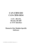
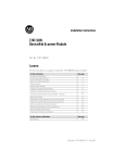
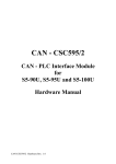
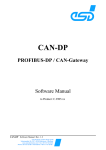
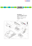
CAN-Control-I/O
Manual of the
Module Specific Software
CAN-Control-I/O Software Rev. 1.1
NOTE
The information in this document has been carefully checked and is believed to be entirely reliable. esd
makes no warranty of any kind with regard to the material in this document, and assumes no
responsibility for any errors that may appear in this document. esd reserves the right to make changes
without notice to this, or any of its products, to improve reliability, performance or design.
esd assumes no responsibility for the use of any circuitry other than circuitry which is part of a product
of esd gmbh.
esd does not convey to the purchaser of the product described herein any license under the patent rights
of esd gmbh nor the rights of others.
esd electronic system design gmbh
Vahrenwalder Str. 205
D-30165 Hannover
Germany
Phone:
FAX:
E-mail:
Internet:
+49-511-372-980
+49-511-633-650
[email protected]
http://www.esd-electronics.com
This document shall not be duplicated, nor its contents used for any purpose, unless express permission
has been granted.
Copyright by esd
CAN-Control-I/O Software Rev. 1.1
Manual File:
I:\TEXTE\DOKU\MANUALS\CAN\LASCON\IO\LCIO-11S.EN6
Date of Print:
20.10.98
Described Software Revision:
CAN Kernel :
see manual 'esd Protocol for CAN Modules'
esd Protocol :
Module-specific Implementation:
Revision 'a'
The designation of the firmware implemented is labelled on the EPROM within the case of the module. The meaning of
the characters is as follows:
CAN / lio6 1d a a
*
*
*
*
*
*
*
*
*
Designation of module )software (module name)
*
*
*
*
*
*
*
*
*
*
Revision no. of the CAN
kernel software (general
firmware)
)-
*
*
*
*
*
*
*
*
*
*
Revision no. of esd CAN
protocol (general firmware) )Revision letter of the modulespecific implementation )-
*
*
*
*
*
*
The above shown example is from a CAN-Control-I/O module with the CAN kernel revision '1.d', esd protocol revision
'a' and the module-specific firmware revision 'a'.
Changes in the chapters
The changes in the user's manual listed below may encompass changes in the firmware, as well as
changes in the description of the facts.
Firmware Manual
Version
Chapter
-
1.1
CAN-Control-I/O Software Rev. 1.1
Changes versus last manual revision
First English issue.
Content
Page
1. Overview . . . . . . . . . . . . . . . . . . . . . . . . . . . . . . . . . . . . . . . . . . . . . . . . . . . . . . . . . . . . . . 1 - 1
1.1 What is Where? . . . . . . . . . . . . . . . . . . . . . . . . . . . . . . . . . . . . . . . . . . . . . . . . . . . 1 - 1
1.2 Default Settings . . . . . . . . . . . . . . . . . . . . . . . . . . . . . . . . . . . . . . . . . . . . . . . . . . . 1 - 3
2. Local Software Mode of Operation . . . . . . . . . . . . . . . . . . . . . . . . . . . . . . . . . . . . . . . . .
2.1 General on Setting and Reading the Digital Outputs and Inputs . . . . . . . . . . . . . . .
2.1.1 Identifier . . . . . . . . . . . . . . . . . . . . . . . . . . . . . . . . . . . . . . . . . . . . . . . . .
2.1.2 Module-No. . . . . . . . . . . . . . . . . . . . . . . . . . . . . . . . . . . . . . . . . . . . . . . .
2.1.3 Count Mode of the Inputs and Outputs . . . . . . . . . . . . . . . . . . . . . . . . . .
2.2 Functions of the Tx identifiers . . . . . . . . . . . . . . . . . . . . . . . . . . . . . . . . . . . . . . . .
2.2.1 Start the Transmission of a Tx Frame . . . . . . . . . . . . . . . . . . . . . . . . . . . .
2.2.2 Transmitting the Input Status (I0...I64) by means of TxId1 . . . . . . . . . . .
2.2.3 Status Messages of Outputs by means of TxId2 . . . . . . . . . . . . . . . . . . . .
2.2.4 Transmission the Output Driver’s Supply Voltage Values at TxId3 . . . . .
2.3 Setting the Outputs by RxId1 . . . . . . . . . . . . . . . . . . . . . . . . . . . . . . . . . . . . . . . . .
2-1
2-1
2-1
2-2
2-3
2-4
2-4
2-5
2-6
2-8
2-9
3. User Parameter . . . . . . . . . . . . . . . . . . . . . . . . . . . . . . . . . . . . . . . . . . . . . . . . . . . . . . . . .
3.1 Overview of the User Parameters . . . . . . . . . . . . . . . . . . . . . . . . . . . . . . . . . . . . . .
3.2 Description of the User Parameters . . . . . . . . . . . . . . . . . . . . . . . . . . . . . . . . . . . .
3.2.1 First Tx-Activate Delay (Parameter 0) . . . . . . . . . . . . . . . . . . . . . . . . . . .
3.2.2 Mask for Output Error and Status Message (Parameter 2) . . . . . . . . . . . .
3.2.3 Setting of the Error-Hold-Time (Parameter 3) . . . . . . . . . . . . . . . . . . . . .
3.2.4 Input Masks (Parameters 4...7) . . . . . . . . . . . . . . . . . . . . . . . . . . . . . . . .
3.2.5 Definition of the Voltage Thresholds (Parameters 8...15) . . . . . . . . . . . . .
3-1
3-1
3-3
3-3
3-4
3-5
3-6
3-7
4. LED Display . . . . . . . . . . . . . . . . . . . . . . . . . . . . . . . . . . . . . . . . . . . . . . . . . . . . . . . . . . . 4 - 1
4.1 Error LED . . . . . . . . . . . . . . . . . . . . . . . . . . . . . . . . . . . . . . . . . . . . . . . . . . . . . . . 4 - 1
4.2 VCC OK LED . . . . . . . . . . . . . . . . . . . . . . . . . . . . . . . . . . . . . . . . . . . . . . . . . . . . 4 - 1
CAN-Control-I/O Software Rev. 1.1
i-1
i-2
CAN-Control-I/O Software Rev. 1.1
Overview
1. Overview
1.1 What is Where?
The description of the esd-CAN modules is divided into three manuals which are handed out in one
file.
CAN
MODULE xy
Manual of the
Module-Specific
Software
1
CAN Application
Layer
LMT, NMT and DBT
for
esd CAN Modules
esd Protocol
for
CAN Modules
2a
2
CAN
MODULE xy
optional
Hardware
Manual
3
The first manual contains the software features and the parameters which are only significant for this
module. The manual can be used independently from the chosen CAN protocol:
CAN-Control-I/O
Manual of the Module-Specific Software
Here, for instance, the functions of the type-specific firmware, the allocation of the COBs (CALCommunication Objects) and identifiers and the allocation of the user parameters are described.
CAN-Control-I/O Software Rev. 1.1
1-1
Overview
The second manual contains general software descriptions which are valid for all esd-CAN modules
which are operated by means of the same protocol.
Two different protocols are available for the modules: The esd-CAN protocol and the CMS protocol.
The protocols are independent from each other and are used alternatively. Depending on the
implemented protocol, one of the following two manuals is therefore valid for the module:
The esd-CAN protocol is described in the manual:
esd Protocol for CAN Modules
It offers the user the possibility to parameterize the esd-CAN modules by means of an initialization
identifier ($700). By means of this protocol identifiers can be assigned to the module, user parameters
can be set and watchdog functions can be activated.
Alternatively, the modules can be controlled by the CMS protocol. If this protocol is implemented (*),
the manual
CAN-Application Layer LMT, NMT and DBT in esd Modules
for the CMS option is to be consulted. Here the translation of CMS services of
the layer management (LMT),
the network management (NMT) and
the identifier distributor (DBT)
in esd-CAN modules is explained.
The third manual contains the hardware description of the module. General as well as module-specific
explanations about the hardware are included in the manual. For instance notes on installation and plug
assignments can be found here.
CAN-Control-I/O
Hardware Manual
(*) At the moment (10.1997) a CMS implementation for this module is not yet available.
1-2
CAN-Control-I/O Software Rev. 1.1
Overview
1.2 Default Settings
The default settings of the module are active, if one or more of the following conditions apply:
-
The position of the coding switches after a RESET or a power-on had been set to '00' and has
then been set to another value.
-
A default RESET has been triggered on the module by means of the esd-CAN protocol.
-
The data of the I²C EEPROM are not OK (e.g. EEPROM not inserted).
Individual parameters can be changed without affecting the default setting of other parameters. Changes
in parameters only remain active after a RESET, if they have been stored in the EEPROM.
Default values in operation of the module with the esd-CAN protocol
INIT Id.
Identifier
(*)
(*)
in all operating modes $700
3 TxIds and 1 RxId
The default value of the identifiers is determined by the
setting of the coding switch in the front panel.
The 4 identifiers are distinguished by means of the
identifier bits id1 and id2.
Module no.
= setting of the coding switch
CAN bitrate
= setting of the jumper J220 (1 Mbits/s)
When allocating identifiers of other modules on the CAN, the user has to take care that no identifier is assigned twice!
Table 1.2.1: Default settings of the module in operation with the esd protocol
CAN-Control-I/O Software Rev. 1.1
1-3
Overview
Default values in operation of the module with the CAL protocol
Manufacturer name
ASCII 'esd_han'
Product name
ASCII 'LIO64'
Module ID
= setting of the coding switch
Module name
ASCII 'LIO64' + setting of the coding switches
CAN bitrate
= setting of jumper J220 (1 Mbits/s)
After a default RESET a configuration download to the module by means of the NMT protocol is
absolutely necessary!
The assignment of the COBs is not yet known (10.1997).
Table 1.2.2: Default adjustments of the module in operation with CAL
1-4
CAN-Control-I/O Software Rev. 1.1
Overview
User parameter
first Tx_activate_delay
Default setting
[HEX]
Comment
$03E8
(1000 ms)
module transmits at the earliest 1 s
after power-on or RESET on the bus
outerr/vccmask
$FFFF
transmission of status message in
case of rising and falling edge of a
status bit
error_hold_time
$0010
(16 ms)
error hold time
input_change_mask_63-48
$FFFF
input_change_mask_47-32
$FFFF
input_change_mask_31-16
$FFFF
input_change_mask_15-0
$FFFF
vccdef_7
$8B53
vccdef_6
$8B53
vccdef_5
$8B53
vccdef_4
$8B53
vccdef_3
$8B53
vccdef_2
$8B53
vccdef_1
$8B53
vccdef_0
$8B53
transmission of all input states, if at
least one input changes it’s state
switching level of the supply voltage
monitor for each supply voltage is
default
VMIN = 17,8 V and
VMAX = 29,8 V
Table 1.2.3: Default settings of the user parameters of the module
The user parameters will be explained in detail in a special chapter.
CAN-Control-I/O Software Rev. 1.1
1-5
1-6
CAN-Control-I/O Software Rev. 1.1
Local Software Mode of Operation
2. Local Software Mode of Operation
2.1 General on Setting and Reading the Digital Outputs and Inputs
2.1.1 Identifier
When operating with the default parameters, the digital inputs and outputs of the CAN-Control-I/O
module are read or set by means of the identifier set at the coding switches. The 2 LSB distinguish the
various identifiers.
The identifiers can be determined as follows:
identifier = $200 +[(coding_switch_setting -1) x 8]
For the setting of the coding switch only values between $1 and $F are permitted. (If the setting is $0
when power is switched on, a default RESET is generated. The default RESET sets all parameters
(even the parameters that are stored in the EEPROM) to the factory setting!)
Identifier bits
Identifier
id11...id8
id7....id4
010.0
010.0
010.0
Setting of
coding
switch
Function
id3 id2 id1
0
0
0
RxId1
Setting the 32 outputs
0
0
1
TxId1
Transmitting the status of 64 inputs
0
1
0
TxId2
Transmitting the programmed value of 32
outputs
0
1
1
TxId3
Transmitting the status of the supply voltage
of the output groups
Table 2.1.1: Assignment of the identifiers in default position
CAN-Control-I/O Software Rev. 1.1
2-1
Local Software Mode of Operation
The following table shows the assignment of the identifers for the coding switch settings 1, 2 and 3 as
an example:
Coding switch setting
(= module number)
Default identifier values
[HEX]
Identifier
1
200
201
202
203
RxId1
TxId1
TxId2
TxId3
2
208
209
20A
20B
RxId1
TxId1
TxId2
TxId3
3
210
211
212
213
RxId1
TxId1
TxId2
TxId3
Table 2.1.2 Example for the default settings of the identifiers
The identifiers are freely programmable by means of the CAN. The programmed identifiers replace the
set default identifiers.
The module transmits the level status of the 64 digital inputs on the Tx identifier TxId1. The status
message of the output channels is transmitted on Tx identifier TxId2. The status message of the supply
voltages for the output groups is transmitted on Tx identifier TxId3.
The outputs are set by means of Rx identifier RxId1.
2.1.2 Module-No.
The module-no. is used to identify the module during the initialition by the esd CAN protocol. In the
default state of the module the value of the module-no. is set by the coding switch.
When the The module-no. that is used to identify the module during th configuration when it is
configurated
2-2
CAN-Control-I/O Software Rev. 1.1
Local Software Mode of Operation
2.1.3 Count Mode of the Inputs and Outputs
The 64 inputs of the module are counted in this manual, similar to the hardware manual of the module,
from 0 to 63 (I0...I63).
The 32 outputs are named Q0 to Q31.
The 32 outputs are divided into 8 groups. The outputs of each group are set by one driver circuit that
has it’s own supply voltage connection pins. The output groups are named as follows:
Outputs
Output group
...
...
...
...
...
...
...
...
7
6
5
4
3
2
1
0
Q28
Q24
Q20
Q16
Q12
Q8
Q4
Q0
Q31
Q27
Q23
Q19
Q15
Q11
Q7
Q3
Table 2.1.3 Assignment of the outputs to the output groups
CAN-Control-I/O Software Rev. 1.1
2-3
Local Software Mode of Operation
2.2 Functions of the Tx identifiers
2.2.1 Start the Transmission of a Tx Frame
The transmission of a Tx frame can be initiated as follows:
1. Cyclic
The transmission can be initiated cyclically, if the cycle time is set by the according parameter ‘TxActivate-Time for TxId...’. This parameter can be set by use of the esd CAN protocol (refer to
manual ‘esd Protocol for CAN-Modules’). The factory setting of the cycle time for TxId3 is 10 s.
2. Remote Request
The transmission of a Tx frames can always be requested by a RTR frame.
3. Alternation of Tx Data
If the data of an identifier alternate, this can initiate the transmission of one or more identifiers, if
this function is enabled.
The enabling is done by the user parameters, which are described in a separate chapter. With the
factory settings of the user parameters this function is enabled for each Tx identifier.
2-4
CAN-Control-I/O Software Rev. 1.1
Local Software Mode of Operation
2.2.2 Transmitting the Input Status (I0...I64) by means of TxId1
The module transmits the status of the 64 digital inputs by means of the eight-byte containing message
of the identifier. The length of the message is always eight bytes.
If a 'high signal' applies to an input, the respective bit of the transmitted bytes is set to '1' (on). The
same is valid for the 'low' level of an input.
TxId
Byte 1
Byte 2
Bit...
Bit...
7 6 5 4 3 2 1 0 7 6 5 4 3 2 1 0 7 6
TxId1
Input I...
Byte 3
Byte 4
Bit...
Bit...
5 4 3 2 1 0 7 6 5 4 3 2 1 0
63 62 61 60 59 58 57 56 55 54 53 52 51 50 49 48 47 46 45 44 43 42 41 40 39 38 37 36 35 34 33 32
TxId
Byte 5
Byte 6
Bit...
Bit...
7 6 5 4 3 2 1 0 7 6 5 4 3 2 1 0 7 6
TxId1
Input I...
Byte 7
Byte 8
Bit...
Bit...
5 4 3 2 1 0 7 6 5 4 3 2 1 0
31 30 29 28 27 26 25 24 23 22 21 20 19 18 17 16 15 14 13 12 11 10 9 8 7 6 5 4 3 2 1 0
Table 2.2.1: Reading the inputs I0 to I64 by TxId1
The enabling of the transmission of the input status, if at least one input signal alternates it’s state is
done by the user parameters ‘input_change_mask_...’.
CAN-Control-I/O Software Rev. 1.1
2-5
Local Software Mode of Operation
2.2.3 Status Messages of Outputs by means of TxId2
The module can send status messages at Tx identifier TxId2. The data length is always 7 bytes.
The transmission can be started by an edge change of error signals of the output drivers or a change of
the supply voltage level of the drivers (i.e. in common with TxId3). Furthermore a transmission of
status messages in periodical intervals or by means of a remote request are possible.
The conditions for activating the transmission of the status message are transmitted by means of the
user parameter ‘outerr/vccmask’.
TxId
TxId2
Byte 1
Byte 2
Byte 3
Byte 4
Bit...
Bit...
Bit...
Bit...
7 6 5 4 3 2 1 0 7 6 5 4 3 2 1 0 7 6 5 4 3 2 1 0 7 6 5 4 3 2 1 0
Read back of the programmed desired values (prog. OUT) of output Q...
31 30 29 28 27 26 25 24 23 22 21 20 19 18 17 16 15 14 13 12 11 10 9 8 7 6 5 4 3 2 1 0
TxId
Byte 5
Byte 6
Byte 7
Byte 8
TxId2
errstat
vccerr
vccstat
not transmitted
Table 2.2.2: Status messages on TxId2
Explanation of the individual status messages:
prog. Out (programmed output value)
31...0...
Byte 1 to 4 return the level of the outputs set by means of the CAN (desired value).
'1' --< output active (on)
'0' --< output not active (off)
errstat
(error status)
Byte 5 returns the error status of the 8 output groups in binary code. If an error signal
of a groups is active, the according bit is set to ‘1’.
Bits of parameter
errstat
7
6
5
4
3
2
1
0
Errors signal of
output groups
7
6
5
4
3
2
1
0
Table 2.2.3: Coding of the error signals of the output groups
2-6
CAN-Control-I/O Software Rev. 1.1
Local Software Mode of Operation
vccerr and
vccstat... Byte 6 and 7 return the status of the output drivers’s supply voltage in binary code.
There is one bit for the VCC error and one bit for the VCC status for each output
group. The assignment of the bits to the output groups is the same as used for the
parameter errstat (refer table above).
The two bits from the parameters vccerr and vccstat that are assigned to one
output group have together the following meaning:
Value of the parameter
bits of one channel
Value of the supply
voltage
Returned status
vccerr
vccstat
0
0
VMIN < VCC < VMAX
OK
(VCC is within the defined
working range)
0
1
VERR < VCC < VMIN
VCC is lower than the defined
working range, but higher
than VERR
1
0
VMAX < VCC
VCC is too high
1
1
VCC < VERR
VCC is too low
Table 2.2.4: Coding of the supply voltages’status signals
Supply voltage monitor switching thresholds:
VERR = 9,0 V
VMIN = 17,8 V
VMAX = 29,8 V
(fix, not programmable)
(default value, programmable by user parameter)
(default value, programmable by user parameter)
CAN-Control-I/O Software Rev. 1.1
2-7
Local Software Mode of Operation
2.2.4 Transmission the Output Driver’s Supply Voltage Values at TxId3
Via Tx identifier TxId3 the module can transmit the measured values of the output drivers supply
voltages. Each value of the eight supply voltages transmitted in one byte:
TxId
Byte 1
Byte 2
Byte 3
Byte 4
Byte 5
Byte 6
Byte 7
Byte 8
TxId3
code_7
code_6
code_5
code_4
code_3
code_2
code_1
code_0
Table 2.2.5: Assignment of TxId3 with the values of the supply voltages
The measured voltage is determined by the following equation:
code
VCC = 5,0V · 11,0 · )
256
The resolution of the measured values is 1 LSB, i.e. 0,2148 V.
The transmission of TxId3 can be initiated using different ways:
1. Cyclic
With the factory settings of the parameters the transmission of the voltage values is initiated
cyclically, every 10 s. This time is set by the esd CAN protocol using the parameter ‘Tx-ActivateTime for TxId3’.
2. Remote Request
The transmission can be requested by a RTR frame.
3. Alternation of the status bytes vccerr or vccstat
Only if the transmission of TxId3 (and TxId2) is enabled by the user parameter
‘outerr/vccstat’, a transmission is initiated if the status bytes alternate. With the default
setting (factory setting) of this user parameter the transmission is enabled for each group.
2-8
CAN-Control-I/O Software Rev. 1.1
Local Software Mode of Operation
2.3 Setting the Outputs by RxId1
The CAN-Control-I/O module receives the data for setting the outputs on Rx identifier RxId1.
Always 4 bytes has to be transmitted. To activate the desired output, the according bit has to be set to
‘1’.
RxId
Byte 1
Byte 2
Bit...
Bit...
7 6 5 4 3 2 1 0 7 6 5 4 3 2 1 0 7 6
RxId1
Output Q...
Byte 3
Byte 4
Bit...
Bit...
5 4 3 2 1 0 7 6 5 4 3 2 1 0
31 30 29 28 27 26 25 24 23 22 21 20 19 18 17 16 15 14 13 12 11 10 9 8 7 6 5 4 3 2 1 0
Table 2.3.1: Setting the outputs Q0 to Q31
The status of the outputs after a RESET is '0' in operation with the default parameters.
CAN-Control-I/O Software Rev. 1.1
2-9
2 - 10
CAN-Control-I/O Software Rev. 1.1
User parameter
3. User Parameter
3.1 Overview of the User Parameters
If the module is run by the esd protocol, the user parameters are transmitted by means of the command
'setting the user parameters' ($86) on byte 5 and 6 of the INIT-Id ($700).
All user parameters have always to be transmitted as 16-bit value with byte 5 as MSB!
The sequence for transmitting ans receiving the user parameters is described in detail in an other
manual called ‘esd Protocol for CAN Modules’
In this manual only the module-specific user parameters are described.
The variables transmitted by means of the user parameters partly become active instantly or only after
the transmission of a 'save config'-command to the module and a following RESET.
If the CMS protocol is implemented, the user parameters are set by a configuration download (NMT).
The format of the configuration-download file has not been known at the time this manual went into
print (10.1997).
CAN-Control-I/O Software Rev. 1.1
3-1
User parameter
Following table gives an overview of the user parameters of the module:
User parameter
No.
Parameter
Value range
Default settings
$0000...$FFFF
(0...65535 ms)
$03E8
(1000 ms)
-
-
$00
first Tx_activate_delay
$01
reserved
$02
outerr/vccmask
$0000...$FFFF
$FFFF
$03
error_hold_time
$0001...$00FF
$0010
$04
input_change_mask_63-48
$0000...$FFFF
$FFFF
$05
input_change_mask_47-32
$0000...$FFFF
$FFFF
$06
input_change_mask_31-16
$0000...$FFFF
$FFFF
$07
input_change_mask_15-0
$0000...$FFFF
$FFFF
$08
vccdef_7
$0000...$FFFF
$8B53
$09
vccdef_6
$0000...$FFFF
$8B53
$0A
vccdef_5
$0000...$FFFF
$8B53
$0B
vccdef_4
$0000...$FFFF
$8B53
$0C
vccdef_3
$0000...$FFFF
$8B53
$0D
vccdef_2
$0000...$FFFF
$8B53
$0E
vccdef_1
$0000...$FFFF
$8B53
$0F
vccdef_0
$0000...$FFFF
$8B53
Table 3.1.1: User parameter of the module
On the following pages the individual user parameters of the module will be explained in detail.
3-2
CAN-Control-I/O Software Rev. 1.1
User parameter
3.2 Description of the User Parameters
3.2.1 First Tx-Activate Delay (Parameter 0)
Parameter 0 transmits the delay time which is to pass before the module initiates the transmission of Tx
frames after a RESET. The delay time is to secure that all modules operate rigidly on the bus before the
module starts transmitting.
The changed parameter becomes only active after a 'save config'-command (refer to esd protocol for
CAN modules) with a following RESET.
User parameter no.
(=sub command no.)
Parameter
Value range
Default
setting
$00
first_Tx_activate_delay
$0000...$FFFF
0...65535 ms
$2710
10 s
Table 3.2.1: User parameter 0
CAN-Control-I/O Software Rev. 1.1
3-3
User parameter
3.2.2 Mask for Output Error and Status Message (Parameter 2)
By means of parameter 2 for each output group of the CAN-Control-I/O module it can be chose, if a
transmission shall be initiated, when the status bytes alternates (L-<H edge or H-<L edge of at least one
parameter’s bit).
User parameter no.
(=sub command no.)
Parameter
Value range
Default
setting
$02
outerr/vccmask
$0000...$FFFF
$FFFF
Table 3.2.2: User parameter 2
For the evaluation of this user parameter the two bytes are considered separately in the format $xx.yy.
The first byte ‘xx’is used for masking the general error status of the group (errstat) and the second
byte ‘yy’is used for masking the VCC status of the groups (vccerr/vccstat):
Bits of user parameter
outerr/vccmask ->
15 14 13 12 11 10 9
enables an error message, if
the following error byte
alternates ->
...in the output group ->
8
7
errstat
7
6
5
4
3
6
5
4
3
2
1
0
vccerr/vccstat
2
1
0
7
6
5
4
3
2
1
0
Table 3.2.3: Assignment of the output groups to the bits of the user parameter 2
Comments to the bits 15...8 (Byte ‘xx’):
Is one of these bits set to ‘1’, this has effects to the initiation of transmission of frames and to the
LED display in the front panel:
1. An alternation of the common error status errstat of the according group initiates a
transmission of an error message via TxId2.
2. An error in the according output group activates the signal ‘Err-LED’ (error display is
activated).
Comments to the bits 7...0 (Byte ‘yy’):
Is one of these bits set to ‘1’, this has effects to the initiation of transmission of frames and to the
LED display in the front panel, too:
1. An alternation of the supply voltage monitor’s status vccerr/vccstat of the according
output group initiates a transmission of an error message via TxId2 and a transmission of the
voltage values via TxId3.
2. Is the signal vccerr of the according output group active, the signal ‘VCC-OK’is deactivated
(VCC LED is ‘off’or ‘flashing’).
3-4
CAN-Control-I/O Software Rev. 1.1
User parameter
3.2.3 Setting of the Error-Hold-Time (Parameter 3)
By means of parameter 3 the Error-Hold-Time is set for the common error message (errstat) for all
output groups together.
User parameter no.
(=sub command no.)
Parameter
Value range
Default
setting
$03
error_hold_time
$0000...$FFFF
$0010
(16 ms)
Table 3.2.4: User parameter 3
The Error-Hold-Time is used for holding the error signal active. This is necessary, because the error
signal is set inactive together with the output signal by the automatically internal protection circuit of
the driver. The output is set active again automatically after a wait time TOFF, even if the reason for the
error is still present. This would cause an alternating error output signal.
The following figure shows a principle timing example:
Output_nominal
Output_actual
TON (ca. 12 ms)
TOFF = 64 x TON
Overcurrent
Err_out (Device)
error_hold_time
Err_out (CAN)
$
TON
Fig. 3.2.5: Timing example of the error signal
After the first error signal is activated, the Error-Hold-Time shall prevent the deactivation of the
following error signal for the duration of at least TON. Therefore the value of error_hold_time
has always be set to values greater than TON.
CAN-Control-I/O Software Rev. 1.1
3-5
User parameter
3.2.4 Input Masks (Parameters 4...7)
The parameters 4 to 7 define, which input shall be determined for the initiation of the transmission of
the status of all inputs via TxId1. At least one input has to be selected. Both, the rising and the falling
edges of an input signal can initiate a transmission (H-<L edge or L-<H edge).
If the parameter bit is set to '1', the module transmits the data to the CAN at an edge change of the
according input.
User parameter no.
(=sub command no.)
Parameter
Value range
Default
setting
$04
input_change_mask_63-48
$0000...$FFFF
$FFFF
$05
input_change_mask_47-32
$0000...$FFFF
$FFFF
$06
input_change_mask_31-16
$0000...$FFFF
$FFFF
$07
input_change_mask_15-0
$0000...$FFFF
$FFFF
Table 3.2.6: User parameters 4...7
Bits of the user parameter
input_change_mask_63-48 ->
15 14 13 12 11 10 9
8
7
6
5
4
3
2
1
0
mask input I...->
63 62 61 60 59 58 57 56 55 54 53 52 51 50 49 48
Bits of the user parameter
15 14 13 12 11 10 9
input_change_mask_47-32 ->
8
7
6
5
4
3
2
1
0
mask input I...->
47 46 45 44 43 42 41 40 39 38 37 36 35 34 33 32
Bits of the user parameter
15 14 13 12 11 10 9
input_change_mask_31-16 ->
8
7
6
5
4
3
2
1
0
mask input I...->
31 30 29 28 27 26 25 24 23 22 21 20 19 18 17 16
Bits of the user parameter
15 14 13 12 11 10 9
8
7
6
5
4
3
2
1
0
15 14 13 12 11 10 9
8
7
6
5
4
3
2
1
0
input_change_mask_15-0 ->
mask input I...->
Table 3.2.7: Assignment of the user parameter bits to the inputs
3-6
CAN-Control-I/O Software Rev. 1.1
User parameter
3.2.5 Definition of the Voltage Thresholds (Parameters 8...15)
By means of the parameters 8 to 15 the voltage thresholds of the output driver’s voltage monitor can
be defined. There is one user parameter for each output group.
User parameter no.
(=sub command no.)
Parameter
Value range
Default
setting
$08
vccdef_7
$0000...$FFFF
$8B53
$09
vccdef_6
$0000...$FFFF
$8B53
$0A
vccdef_5
$0000...$FFFF
$8B53
$0B
vccdef_4
$0000...$FFFF
$8B53
$0C
vccdef_3
$0000...$FFFF
$8B53
$0D
vccdef_2
$0000...$FFFF
$8B53
$0E
vccdef_1
$0000...$FFFF
$8B53
$0F
vccdef_0
$0000...$FFFF
$8B53
Table 3.2.8: User parameter 8...15
CAN-Control-I/O Software Rev. 1.1
3-7
User parameter
Bits of user parameter ->
15 14 13 12 11 10 9
8
7
6
5
4
3
2
1
Output group for user parameter
vccdef_7 ->
VMAX Output group 7
VMIN Output group 7
Output group for user parameter
vccdef_6 ->
VMAX Output group 6
VMIN Output group 6
Output group for user parameter
vccdef_5 ->
VMAX Output group 5
VMIN Output group 5
Output group for user parameter
vccdef_4 ->
VMAX Output group 4
VMIN Output group 4
Output group for user parameter
vccdef_3 ->
VMAX Output group 3
VMIN Output group 3
Output group for user parameter
vccdef_2 ->
VMAX Output group 2
VMIN Output group 2
Output group for user parameter
vccdef_1 ->
VMAX Output group 1
VMIN Output group 1
Output group for user parameter
vccdef_0 ->
VMAX Output group 0
VMIN Output group 0
0
Table 3.2.9: Assignment of the user parameters 4...7 to the output groups
The value that must be set for a desired voltage threshold (VMAX and VMIN ) has is determined as
follows:
code = )
VMAX/MIN · 256
5,0V · 11,0
with
code...
VMIN/MAX...
3-8
value, that must be transmitted
desired voltage threshold
CAN-Control-I/O Software Rev. 1.1
LED Display
4. LED Display
4.1 Error LED
The error LED lights, if an error condition is active for at least one output and the error message is
enabled.
The error condition is active, if an output driver has activated his error signal. The error message can
be enabled by the user parameter outerr/vccmask.
The error message can also be transmitted in the byte errstat via TxId2.
4.2 VCC OK LED
Basic condition for the illumination of the VCC OK LED is the enabling by the user parameter
outerr/vccmask. If an output group is not enabled, the status of the supply voltage is not
considered for further evaluation.
The status of a supply voltage is ‘OK’if the voltage level is between VMIN and VMAX.
The status of the supply voltages can also be transmitted in the bytes vccerr and vccstat via
TxId2.
Luminous status
Meaning of the luminous status
Constantly OFF
None of the supply voltages is OK.
Flashing
The level of at least one supply voltage is OK and the level of at least one
other supply voltage is not OK.
(Evaluation only of groups, that are enabled.)
Constantly ON
The level of every enabled supply voltage is OK.
Table 4.2.1: Luminous states of the VCC OK LED
CAN-Control-I/O Software Rev. 1.1
4-1