1
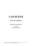
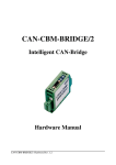
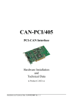
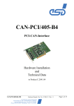
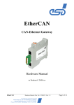
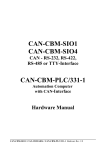
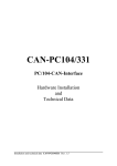
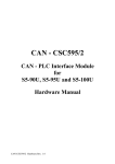
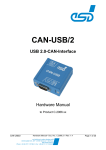
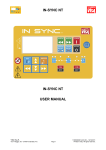
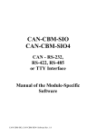
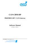
CAN-CBM-DP Profibus-DP / CAN-Gateway DN-CBM-DP Profibus-DP / DeviceNet-Gateway Hardware Manual to Product C.2844.03/.05 and C.2846.02 CAN-CBM-DP / DN-CBM-DP Hardware-Manual • Rev. 1.7 esd electronic system design gmbh Vahrenwalder Str. 207 • 30165 Hannover • Germany www.esd-electronics.com • Fax: 0511/37 29 8-68 Phone: 0511/37 29 80 • International: +49-5 11-37 29 80 Page 1 of 41 NOTE The information in this document has been carefully checked and is believed to be entirely reliable. esd makes no warranty of any kind with regard to the material in this document, and assumes no responsibility for any errors that may appear in this document. esd reserves the right to make changes without notice to this, or any of its products, to improve reliability, performance or design. esd assumes no responsibility for the use of any circuitry other than circuitry which is part of a product of esd gmbh. esd does not convey to the purchaser of the product described herein any license under the patent rights of esd gmbh nor the rights of others. esd electronic system design gmbh Vahrenwalder Str. 207 30165 Hannover Germany Phone: Fax: E-mail: Internet: +49-511-372 98-0 +49-511-372 98-68 [email protected] www.esd-electronics.com USA / Canada: esd electronics Inc. 525 Bernardston Road Suite 1 Greenfield, MA 01301 USA Phone: Fax: E-mail: Internet: Page 2 of 41 +1-800-732-8006 +1-800-732-8093 [email protected] www.esd-electronics.us Hardware-Manual • Rev. 1.7 CAN-CBM-DP / DN-CBM-DP Document file: I:\Texte\Doku\MANUALS\CAN\CBM\DP\Englisch\Hardware\CBMDP17H.en9 Date of print: 2008-02-26 PCB versions: CPU331 Rev. 1.1 CBM-DP Rev. 1.1 CBMPB Rev. 1.1 Changes in the chapters The changes in the user’s manual listed below affect changes in the hardware as well as changes in the description of the facts only. Chapter Changes versus previous version 1.1 Description of PROFIBUS-DP data range inserted. 1.2 Description of PROFIBUS-DP data range inserted. Technical details are subject to change without notice. CAN-CBM-DP / DN-CBM-DP Hardware-Manual • Rev. 1.7 Page 3 of 41 This page is intentionally left blank. Page 4 of 41 Hardware-Manual • Rev. 1.7 CAN-CBM-DP / DN-CBM-DP Contents Page 1. Overview . . . . . . . . . . . . . . . . . . . . . . . . . . . . . . . . . . . . . . . . . . . . . . . . . . . . . . . . . . . . . . . . . 7 1.1 Module Description CAN-CBM-DP . . . . . . . . . . . . . . . . . . . . . . . . . . . . . . . . . . . . . . . 7 1.2 Module Description DN-CBM-DP . . . . . . . . . . . . . . . . . . . . . . . . . . . . . . . . . . . . . . . . 9 1.3 Front View with Connectors and Coding Switches . . . . . . . . . . . . . . . . . . . . . . . . . . . 10 1.4 Summary of Technical Data . . . . . . . . . . . . . . . . . . . . . . . . . . . . . . . . . . . . . . . . . . . . 11 1.4.1 General Technical Data . . . . . . . . . . . . . . . . . . . . . . . . . . . . . . . . . . . . . . . . 11 1.4.2 Microcontroller Circuit . . . . . . . . . . . . . . . . . . . . . . . . . . . . . . . . . . . . . . . . 12 1.4.3 CAN/DeviceNet Interface . . . . . . . . . . . . . . . . . . . . . . . . . . . . . . . . . . . . . . 12 1.4.4 Profibus-DP Interface . . . . . . . . . . . . . . . . . . . . . . . . . . . . . . . . . . . . . . . . . 13 1.4.5 Serial Interface . . . . . . . . . . . . . . . . . . . . . . . . . . . . . . . . . . . . . . . . . . . . . . 13 1.5 Order Information . . . . . . . . . . . . . . . . . . . . . . . . . . . . . . . . . . . . . . . . . . . . . . . . . . . 15 2. Circuit Description . . . . . . . . . . . . . . . . . . . . . . . . . . . . . . . . . . . . . . . . . . . . . . . . . . . . . . . . 2.1 CAN/DeviceNet Circuit . . . . . . . . . . . . . . . . . . . . . . . . . . . . . . . . . . . . . . . . . . . . . . . 2.1.1 Interface Circuit . . . . . . . . . . . . . . . . . . . . . . . . . . . . . . . . . . . . . . . . . . . . . . 2.2 Profibus-DP Circuit . . . . . . . . . . . . . . . . . . . . . . . . . . . . . . . . . . . . . . . . . . . . . . . . . . 2.3 Serial Interface . . . . . . . . . . . . . . . . . . . . . . . . . . . . . . . . . . . . . . . . . . . . . . . . . . . . . . 2.3.1 Configuration . . . . . . . . . . . . . . . . . . . . . . . . . . . . . . . . . . . . . . . . . . . . . . . 2.3.2 Connection of Various Serial Interfaces . . . . . . . . . . . . . . . . . . . . . . . . . . . . 2.4 Function of Coding Switches . . . . . . . . . . . . . . . . . . . . . . . . . . . . . . . . . . . . . . . . . . . 17 17 17 19 20 20 21 24 3. Appendix . . . . . . . . . . . . . . . . . . . . . . . . . . . . . . . . . . . . . . . . . . . . . . . . . . . . . . . . . . . . . . . . 3.1 Connector Assignments . . . . . . . . . . . . . . . . . . . . . . . . . . . . . . . . . . . . . . . . . . . . . . . 3.1.1 CAN-CBM-DP: CAN-Bus (X400, 5-pin Combicon Style) . . . . . . . . . . . . . . 3.1.2 DN-CBM-DP: DeviceNet (X400, 5-pin Combicon Style) . . . . . . . . . . . . . . 3.1.3 Profibus-DP Interface (X100-CBMPB, 9-pin DSUB female) . . . . . . . . . . . . 3.1.4 RS-232 Interface (X100-SIO331, 9-pin DSUB male) . . . . . . . . . . . . . . . . . . 3.1.5 Connection Lines for the RS-232 Interface to a PC . . . . . . . . . . . . . . . . . . . 3.1.6 RS-422 Interface (X100-SIO331, 9-pin DSUB male) . . . . . . . . . . . . . . . . . . 3.1.7 RS-485 Interface (X100-SIO331, 9-pin DSUB male) . . . . . . . . . . . . . . . . . . 3.1.8 TTY-passive Interface (X100-SIO331, 9-pin DSUB male) . . . . . . . . . . . . . . 3.1.9 TTY-active Interface (X100-SIO331, 9-pin DSUB male) . . . . . . . . . . . . . . . 3.1.10 Voltage Supply (X101, UEGM) . . . . . . . . . . . . . . . . . . . . . . . . . . . . . . . . . 25 25 25 26 27 28 29 30 31 32 33 34 4. Correctly Wiring Electrically Isolated CAN Networks . . . . . . . . . . . . . . . . . . . . . . . . . . . . 35 5. CAN-Bus Troubleshooting Guide . . . . . . . . . . . . . . . . . . . . . . . . . . . . . . . . . . . . . . . . . . . . . 5.1 Termination . . . . . . . . . . . . . . . . . . . . . . . . . . . . . . . . . . . . . . . . . . . . . . . . . . . . . . . . 5.2 CAN_H/CAN_L Voltage . . . . . . . . . . . . . . . . . . . . . . . . . . . . . . . . . . . . . . . . . . . . . 5.3 Ground . . . . . . . . . . . . . . . . . . . . . . . . . . . . . . . . . . . . . . . . . . . . . . . . . . . . . . . . . . . 5.4 CAN Transceiver Resistance Test . . . . . . . . . . . . . . . . . . . . . . . . . . . . . . . . . . . . . . . CAN-CBM-DP / DN-CBM-DP Hardware-Manual • Rev. 1.7 39 39 40 40 41 Page 5 of 41 This page is intentionally left blank. Page 6 of 41 Hardware-Manual • Rev. 1.7 CAN-CBM-DP / DN-CBM-DP Overview i 1. Overview This manual describes the hardware of the CAN-interface CAN-CBM-DP- and the hardware of the DeviceNet-interface DN-CBM-DP-module together. Differences are noted. 1.1 Module Description CAN-CBM-DP electrical isolation C A N Physical CAN Layer MSTB2,5/5-5,08 CAN CAN Controller SJA1000 Coding Switches +5 V= DC/DC Converter 2x3-pole UEGM Connector Serial EERPOM +5 V= Microcontroller 68331 RS-232, RS-422, RS-485 or TTY Interface Power Supply 24 V(DC) +5 V= Flash EPROM DC/DCConverter +5 V= DSUB9 Connector D P DSUB9 Connector RS-485 DP-Layer DP DP-Slave Controller SPC3 SRAM electrical isolation Fig. 1.1.1: Block-circuit diagram of the CAN-CBM-DP module By means of the module CAN-CBM-DP any Profibus-DP master can be connected to a CAN network. The DP/CAN gateway acts like a slave I/O component on the DP-bus, with a total of up to 300 bytes input and output data. Maximum 244 bytes of the total of 300 bytes can be used as input data (with 56 byte output data) or maximum 244 bytes can be used as output data (with 56 bytes input data). With the CAN gateway you can connect CAN modules with CANopen or layer 2 implementation to e.g. a SIMATIC-S7. There are no limitations on CANopen PDO’s and SDO’s by the gateway and the complete DeviceNet scanner functionality is supported. The number of CAN participants is not limited by the module, too. The module operates internally with a 68331 micro controller, which buffers the CAN and Profibus DP data into the local SRAM. The firmware and configuration data are kept in the Flash EEPROM. Parameters are stored by means of a serial EEPROM. The ISO 11898-compliant CAN interface allows a maximum data-transfer rate of 1 Mbit/s. The Profibus-DP slave interface automatically recognizes all usual bit rates up to 12 Mbit/s. The DP interface as well as the CAN interface are electronically insulated by optocouplers and DC/DC converters. The CAN is connected by means of a 5-pin screw/plug connector in Combicon design. CAN-CBM-DP / DN-CBM-DP Hardware-Manual • Rev. 1.7 Page 7 of 41 i Overview According to standard, the DP interface is equipped with a 9-pin female DSUB connector. The module has a serial interface (default: RS-232) for servicing and configuration. It is connected by means of a male DSUB9. The data mapping of the CAN-I/O data of the DP slave is done by the Profibus Configuration tool, e.g. PLC SIMATIC MANAGER. Additionally a configuration software is available under Windows 95/98 or Windows NT. CANopen is supported as Layer-7 protocol on CAN. Page 8 of 41 Hardware-Manual • Rev. 1.7 CAN-CBM-DP / DN-CBM-DP Overview i 1.2 Module Description DN-CBM-DP DeviceNet electrical isolation Physical Layer DeviceNet MSTB 2,5/5-5,08 CAN CAN Controller SJA1000 Coding Switches Voltage Controller Serial EERPOM 2x3-pole UEGM Connector Microcontroller 68331 RS-232, RS-422, RS-485 or TTY Interface Power Supply 24 V(DC) +5 V= DSUB9 Connector Flash EPROM DC/DCConverter +5 V= DSUB9 Connector D P Serial RS-485 DP-Layer DP DP-Slave Controller SPC3 SRAM electrical isolation Fig. 1.2.1: Block-circuit diagram of the DN-CBM-DP module The module DN-CBM-DP can link any Profibus-DP master to DeviceNet. The DN-CBM-DP gateway acts like a slave I/O component on the DP-bus, with a total of up to 312 bytes input and output data. Maximum 244 bytes of the total of 312 bytes can be used as input data (with 68 byte output data) or maximum 244 bytes can be used as output data (with 68 bytes input data). The module operates internally with a 68331 micro controller, which buffers the DN and Profibus DP data into the local SRAM. The firmware and configuration data are kept in the Flash EEPROM. Parameters are stored by means of a serial EEPROM. The DeviceNet interface is designed according to the DeviceNet Specification Rev.2.0. All DeviceNet bit rates are supported. The Profibus-DP slave interface automatically recognizes all usual bit rates up to 12 Mbit/s. The DP interface as well as the DeviceNet interface are electronically insulated by optocouplers and DC/DC converters. The DeviceNet is connected by means of a 5-pin screw/plug connector in Combicon design. According to standard, the DP interface is equipped with a 9-pin female DSUB connector. The module has a serial interface (default: RS-232) for servicing and configuration. It is connected by means of a male DSUB9. For mapping the I/O data of the DP slave a configuration software is available under Windows 95/98 or Windows NT. DeviceNet is supported as Layer-7 protocols. CAN-CBM-DP / DN-CBM-DP Hardware-Manual • Rev. 1.7 Page 9 of 41 i Overview 1.3 Front View with Connectors and Coding Switches Power Supply LED3 LED 2 LED 1 PROFI ADR. HIGH PROFI ADR. LOW SERIAL 8 Coding Switch SW211 (High) 0 8 Coding Switch SW210 (Low) 0 Serial Interface (DSUB9, male) Power Supply CAN or DeviceNet Profibus-DP (DSUB9, female) Fig. 1.2.1: Position of connectors and control elements PCB CPU331 PCB CBMPB X100-CBMPB (DSUB9, female) Profibus-DP PCB SIO331 X400 CAN/DeviceNet X100-SIO331 (DSUB9, male) Serial Interface Fig. 1.3.2: Internal module structure with PCB designations and connector names (Figure without connector for supply voltage) Page 10 of 41 Hardware-Manual • Rev. 1.7 CAN-CBM-DP / DN-CBM-DP Overview i 1.4 Summary of Technical Data 1.4.1 General Technical Data Nominal voltage 24 V/DC ±10%, Current (at 20°C): max. 125 mA (+20 mA in TTY operation of serial interface) Supply voltage X100-SIO331 X100-CBMPB X101 Connectors X400 (DSUB9, male) - serial interface (DSUB9, female) - Profibus-DP-interface (6-pin screw connector UEGM) 24V-voltage supply (Combicon design, 5-pin MSTB2.5/5-5.08) - CAN or DeviceNet Temperature range 0...50 C ambient temperature Humidity max. 90%, non-condensing Case dimensions (W x H x D) Width: 40 mm, height 85 mm, depth: 83 mm (including hat rail mounting and jutted out connectors DSUB9, without CAN/DeviceNet connectors) Weight approx. 200 g Table 1.4.1: General data of the CAN-CBM-DP and DN-CBM-DP CAN-CBM-DP / DN-CBM-DP Hardware-Manual • Rev. 1.7 Page 11 of 41 i Overview 1.4.2 Microcontroller Circuit Microcontroller 68331 Memory SRAM: 128 k x 16 Bit (optional 512 k x 16 Bit) Flash-EPROM: 128 k x 8 Bit EEPROM: serial I²C-EEPROM (1024 k x 8 Bit) Debug interface for service and programming Table 1.4.2: Microcontroller circuit 1.4.3 CAN/DeviceNet Interface Number of interfaces CAN-CBM-DP: 1 x CAN DN-CBM-DP: 1 x DeviceNet Connection 5-pin Combicon design MSTB2.5/5-5.08 CAN controller SJA1000, CAN 2.0A/B Electrical insulation of CAN interface from other circuits via optocouplers and DC/DC converters (CAN-CBM-DP) Physical Layer CAN (CAN-CBM-DP) Physical Layer according to ISO 11898, transmission rate programmable from 10 kbit/s to 1 Mbit/s Physical Layer DeviceNet (DN-CBM-DP) Physical Layer according to DeviceNet specification Rev. 2.0, bit rate: 125 kbit/s, 250 kbit/s, 500 kbit/s Table 1.4.3: Data of CAN/DeviceNet interface Page 12 of 41 Hardware-Manual • Rev. 1.7 CAN-CBM-DP / DN-CBM-DP Overview i 1.4.4 Profibus-DP Interface Number of Profibus-DP interfaces 1x Profibus-DP Connection 9-pin DSUB female DP controller Siemens Profibus Controller SPC3, DP-Slave Electrical insulation of ProfibusDP from other circuits via optocouplers and DC/DC converters Physical Layer RS-485 Table 1.4.4: Data of Profibus-DP interface 1.4.5 Serial Interface Controller 68331 Interface Standard: RS-232 Options: RS-422, RS-485, TTY active/passive Connection 9-pin DSUB male Table 1.4.5: Data of serial interface CAN-CBM-DP / DN-CBM-DP Hardware-Manual • Rev. 1.7 Page 13 of 41 This page is intentionally left blank. Page 14 of 41 Hardware-Manual • Rev. 1.7 CAN-CBM-DP / DN-CBM-DP Order Information 1.5 Order Information Type Properties Order No. CAN-CBM-DP DP-CAN-Gateway, CAN-layer 2, CAN 2.0A-firmware for 11 bit CAN identifier, RS232 interface, GSD-file C.2844.03 CAN-CBM-DP-2.0B DP-CAN-Gateway, CAN-layer 2, CAN 2.0A/B-firmware for 11 and 29 bit CAN identifier, RS-232 interface, GSD-file C.2844.05 DN-CBM-DP DP-DeviceNet-Gateway, Firmware for 11 bit CAN identifier, RS-232 interface C.2846.02 Instead of RS-232 supplemented by: (to be specified in order) RS-422 adapter RS-485 adapter TTY-20mA passive TTY-20mA active V.1930.02 V.1930.04 V.1930.06 V.1930.08 CAN-CBM-DP-ME English manual 1*) for C.2844.03/05 incl. configuration software (includes hardware and software manual) C.2844.21 DN-CBM-DP-ME English manual 1*) for C.2846.02 incl. configuration software (includes hardware and software manual) C.2846.21 CAN-CBM-DP-ENG English engineering manual 2*) for C.2844.03/05 and C.2846.02 Content: circuit diagrams, PCB top overlay drawing, data sheets of significant components C.2844.25 1*) 2*) ... ... If module and manual are ordered together, the manual is free of charge. This manual is liable for costs, please contact our support. Table 1.5.1: Order information CAN-CBM-DP / DN-CBM-DP Hardware-Manual • Rev. 1.7 Page 15 of 41 This page is intentionally left blank. Page 16 of 41 Hardware-Manual • Rev. 1.7 CAN-CBM-DP / DN-CBM-DP Circuit Description 2. Circuit Description 2.1 CAN/DeviceNet Circuit 2.1.1 Interface Circuit The CAN-CBM-DP module is equipped with an ISO 11898-compliant CAN interface, the DN-CBM-DP with a DeviceNet interface. The same connector in Combicon design is used for the two types, the assignment of the connector, however, differs. The following figures show both interfaces. VCC DC/DC R05ET05 + 100µF/6.3V 5V GND 5V - +5V VC05D150 + CAN_GND - 2.2M 2.2nF/250V~ Optical Coupler HCPL7100 10K VCCin IN +5V CAN Transceiver 82C251/ +5V Si9200 VCCout OUT ENABLE TX00* GND RX00* to CAN Controller VCC GNDin VDD GNDout Optical Coupler HCPL7100 VCCout OUT +5V TX BUSL RX BUSH R/GND GND GNDout CAN_L CAN_H CAN_GND VCCin IN ENABLE GND X400 MSTB2.5/5-5,08 GNDin 2 4 1 n.c. 3 n.c. 5 Fig. 2.1.1: Circuit of CAN interface CAN-CBM-DP CAN-CBM-DP / DN-CBM-DP Hardware-Manual • Rev. 1.7 Page 17 of 41 Circuit Description +5V 1R X400 MSTB2,5/5-5,08 3K6/1% 100µH MC34063A Sense DC SC V+ +V CAP 220pF 22µF/35V SE Comp 1K2/1% V- -V 1 PRLL5819 PRLL5819 CAN_GND 10M 5 10nF/500V~ Opto Coupler HCPL7100 10K VCCin IN +5V CAN Transceiver 82C251/ +5V Si9200 VCCout OUT ENABLE TX00* GND RX00* to CAN Controller VCC GNDin Opto Coupler HCPL7100 VCCout OUT CAN- VDD GNDout +5V TX BUSL RX BUSH R/GND CAN+ 2 4 GND n.c. VCCin 3 IN ENABLE GND GNDout GNDin Fig. 2.1.2: Circuit of DeviceNet interface DN-CBM-DP Page 18 of 41 Hardware-Manual • Rev. 1.7 CAN-CBM-DP / DN-CBM-DP Circuit Description 2.2 Profibus-DP Circuit DC100 DC/DC R05ET05 VCC +5V + + VC100D150 5V GND - CT101B 10µF/6,3V 5V X100 DSUB9, female - RV100 2,2M +5V +5V CV100 2,2nF/250V~ 6 U101 HCPL-0600 R108 270R RTS R109 680R +5V R110 270R & from DP-controller U102 Optocoupler HCPL7110 VCCin IN U105 75176 +5V VCCout GND Rx to DP-controller VCC GNDin OUT +5V R111 1k2 R112 1k2 RxD-/TxD+ (LTG_A) +5V R113 680R R115 100k VCCin 8 R116 100k +5V RxD+/TxD+ (LTG_B) 3 Rx IN ENABLE GNDout +5V Tx GNDout U103 Optocoupler HCPL7110 VCCout GND 4 OUT ENABLE Tx RTS U104A 74HCPL132 CV100 22nF R107 10K R114 270R GND GNDin 5 Fig. 2.2.1: Circuit of Profibus-DP interface Note: The terminating resistors of the Profibus-DB networks have to be connected externally (see EN 50 170)! CAN-CBM-DP / DN-CBM-DP Hardware-Manual • Rev. 1.7 Page 19 of 41 Circuit Description 2.3 Serial Interface 2.3.1 Configuration The physical interface of the serial configuration interface can be configured as an RS-232, RS-422, RS485, TTY-active or TTY-passive interface. For RS-232 operation an RS-232A driver component is used and for the other interfaces piggy-backs are used. The serial interface is controlled by the 68331. The bit rate of the interface can be set by parameters. For each interface type (RS-232, RS-422, RS-485, TTY) a bit rate of up to 38,4 kbit/s is supported. The following bit rates can be set by means of the software. The values in the second column shown the actual bit rates, which result from the controller-internal conversion. Bit rate (set value) [bit/s] Bit rate (actual value) [bit/s] 38,400 19,200 9,600 4,800 2,400 1,200 600 300 38,462 19,231 9,615 4,808 2,404 1,199 600.2 299.9 Table 2.3.1: Adjustable bit rates Page 20 of 41 Hardware-Manual • Rev. 1.7 CAN-CBM-DP / DN-CBM-DP Circuit Description 2.3.2 Connection of Various Serial Interfaces Below the wiring of the serial interfaces is shown. The figures are used to explain the terms for the signals used in the appendix. In the appendix you can also find the circuit diagrams of the various available piggy-backs. The signal terms are exemplary for the connection of the CBM-DP as transmitter (terminal DTE). 2.3.2.1 The RS-232 Interface The input signals CTS, DSR and DCD are not evaluated by the CAN-CBM-DP and DN-CBM-DP! CAN-CBM-DP (Modem, DCE) TxD RxD DTR CTS GND local signal terms Terminal (DTE) 3 RxD 2 TxD 4 CTS 8 (DTR) 5 GND pin numbers of the 9-pole DSUB connector Fig. 2.3.1: Connection diagram for RS-232 operation CAN-CBM-DP / DN-CBM-DP Hardware-Manual • Rev. 1.7 Page 21 of 41 Circuit Description 2.3.2.2 The RS-422 Interface CAN-CBM-DP (Modem, DCE) TxD RxD GND local signal terms Terminal (DTE) 2 Tx+ 7 Tx- 9 Rx+ 4 Rx- 5 GND RxD TxD GND pin numbers of the 9-pole DSUB connector Fig. 2.3.2: Connection diagram for RS-422 operation 2.3.2.3 The RS-485 Interface CAN-CBM-DP (Modem, DCE) TxD Terminal (DTE) 2 Rx/Tx+ 7 Rx/Tx- RxD RxD RTS +5V TxD 1k 150 1k GND local signal terms 9 TERM+ 4 TERM- 5 GND GND pin numbers of the 9-pole DSUB connector Fig. 2.3.3: Connection diagram for RS-485 operation In order to activate the terminating resistor network on the piggy-back, you have to connect pins 9 and 2 and pins 4 and 7 in the DSUB9 connector, for example. Page 22 of 41 Hardware-Manual • Rev. 1.7 CAN-CBM-DP / DN-CBM-DP Circuit Description 2.3.2.4 The TTY(20 mA) Interface CAN-CBM-DP (Modem, DCE) Terminal (DTE) i=20mA +U TxD 2 Tx+ 7 Tx- i=20mA RxD i=20mA -U +U RxD 9 Rx+ 4 Rx- TxD i=20mA -U pin numbers of the 9-pole DSUB connector local signal terms Fig. 2.3.4: Connection diagram for TTY operation (passive) CAN-CBM-DP (Modem, DCE) i=20mA +24V Terminal (DTE) 3 Tx+ 2 Tx- 8 Rx+ 9 Rx- i=20mA RxD TxD GNDA i=20mA +24V RxD local signal terms i=20mA TxD GNDA pin numbers of the 9-pole DSUB connector Fig. 2.3.5: Connection diagram for TTY operation (active) CAN-CBM-DP / DN-CBM-DP Hardware-Manual • Rev. 1.7 Page 23 of 41 Circuit Description 2.4 Function of Coding Switches The coding switches are used to set the PROFIBUS address. On power-on the PROFIBUS address is read from the coding switches. The settings have to be changed before switching on, because changes have no effect during operation. The CAN-CBM-DP/DN-CBM-DP is operated as a slave station whose addresses can be set in the range decimally from 3 to 124 or hexadecimally from $03 to $C7. If an address smaller than 3 is set, address 3 is valid. If an address larger than 124 (decimal) or C7 (HEX) is set, address 124 is valid. The upper coding switch (SW211) is used to set the MSBs, the lower coding switch (SW210) is used to set the LSBs. The CAN identifiers (CAN-CBM-DP) are set by means of a PROFIBUS-DP configuration tool (e.g. SIMATIC manager). Information about this can be found in the ‘CAN-CBM-DP Software Manual’. The MACID for the operation of the DN-CBM-DP module is set by the configuration received from the PLC via PROFIBUS-DP, too. Page 24 of 41 Hardware-Manual • Rev. 1.7 CAN-CBM-DP / DN-CBM-DP Connector Assignments 3. Appendix 3.1 Connector Assignments 3.1.1 CAN-CBM-DP: CAN-Bus (X400, 5-pin Combicon Style) Pin Assignment of the Combicon socket of the module 5 4 3 2 1 Signal Terms: CAN_L, CAN_H ... CAN_GND... Shield... Pin Signal 5 n.c. 4 CAN_H 3 Shield 2 CAN_L 1 CAN_GND CAN signals reference potential of the CAN physical layers connection of shield line (Shield signal is not connected locally on the CANCBM-DP) Pin assignment of an adapter cable 5-pole Combicon to 9-pole DSUB: The 9-pin DSUB connector is assigned in accordance with CiA DS 102. CAN-CBM-DP / DN-CBM-DP Hardware-Manual • Rev. 1.7 Page 25 of 41 Connector Assignments 3.1.2 DN-CBM-DP: DeviceNet (X400, 5-pin Combicon Style) Pin Position: 1 2 3 4 5 Signal terms: V+... V-... CAN+, CAN-... Shield... Page 26 of 41 Pin Assignment: Pin Signal 1 V- 2 CAN- 3 Shield 4 CAN+ 5 V+ Voltage supply feed (UVCC = 24 V ± 4%) Reference potential to V+ and CAN+/CANCAN-signal lines connection of shield line (Shield signal is not connected locally on the DNCBM-DP) Hardware-Manual • Rev. 1.7 CAN-CBM-DP / DN-CBM-DP Connector Assignments 3.1.3 Profibus-DP Interface (X100-CBMPB, 9-pin DSUB female) Pin Position: Pin Assignment: Pin Signal n.c. 1 n.c. 2 RxD+/TxD+ (I/O) 3 RTS (output) 4 GND 5 Signal 6 +5 V 7 n.c. 8 RxD-/TxD- 9 n.c. (output) (I/O) 9-pin DSUB female Signal Terms: RxD+/TxD+... RxD-/TxD- receive and transmission data RTS... control signal for repeater (‘Request To Send’) +5 V... voltage supply for external terminating resistor networks (max. 50 mA) GND... reference potential CAN-CBM-DP / DN-CBM-DP Hardware-Manual • Rev. 1.7 Page 27 of 41 Connector Assignments 3.1.4 RS-232 Interface (X100-SIO331, 9-pin DSUB male) Pin Position: Pin Assignment: Pin Signal (DSR) (input) 6 RTS (output) 7 (CTS) (input) 8 RIN (input) 9 Signal 1 (DCD) (input) 2 RxD (input) 3 TxD (output) 4 DTR (output) 5 GND 9-pin DSUB male The signal name is indicated looked by the CAN-CBM-module. The input signals CTS, DSR and DCD are not evaluated by the CAN-CBM-DP / DN-CBM-DP! Page 28 of 41 Hardware-Manual • Rev. 1.7 CAN-CBM-DP / DN-CBM-DP Connector Assignments 3.1.5 Connection Lines for the RS-232 Interface to a PC The following two figures show the required assignment for RS-232 connection lines between PC and CAN-CBM-DP/DN-CBM-DP. Adapter cable 9-pin DSUB female to 9-pin DSUB female 1,5 m P1 DSUB female 9-pole 5 4 9 3 8 2 7 1 5 6 4 9 3 8 2 7 1 P2 DSUB female 9-pole 6 P1: P2: PC CAN-CBM-DP DN-CBM-DP 1 1 RxD 2 TxD 3 DTR 4 GND 5 6 2 RxD 3 TxD 4 DTR 5 GND 6 7 CTS 8 9 7 RTS 8 (CTS) 9 RIN local signal names used at CBM module Adapter cable 25-pin DSUB female to 9-pin DSUB female 1,5 m P1 DSUB female 25-pole 13 12 11 10 9 8 7 6 5 4 3 2 1 25 24 23 22 21 20 19 18 17 16 15 14 1 RxD CTS 6 7 7 1 6 P2 DSUB female 9-pole 2 RxD 3 TxD 4 DTR 5 GND 6 GND 8 20 8 2 1 TxD 4 5 9 3 CAN-CBM-DP DN-CBM-DP PC 3 4 P2: P1: 2 5 DTR 7 RTS 8 (CTS) 9 RIN local signal names used at CBM module 25 CAN-CBM-DP / DN-CBM-DP Hardware-Manual • Rev. 1.7 Page 29 of 41 Connector Assignments 3.1.6 RS-422 Interface (X100-SIO331, 9-pin DSUB male) Pin Position: Pin Assignment: Pin Signal Tx- 6 (output) Rx+ 7 8 (input) 9 Signal 1 - 2 Tx+ 3 - 4 Rx- 5 GND (output) (input) 9-pin DSUB male Page 30 of 41 Hardware-Manual • Rev. 1.7 CAN-CBM-DP / DN-CBM-DP Connector Assignments 3.1.7 RS-485 Interface (X100-SIO331, 9-pin DSUB male) Pin Position: Pin Assignment: Pin Signal - 6 Rx/Tx- 7 - 8 Term+ (for Rx/Tx+) *1) 9 Signal 1 - 2 Rx/Tx+ 3 - 4 Term- (for Rx/Tx-) *1) 5 GND 9-pin DSUB male *1) ... The signals Term+ and Term- are connected to a terminating resistor network on the PCB. In order to activate the connection, Term+ has to be connected to the Rx/Tx+ signal and Term- with the Rx/Tx- signal. CAN-CBM-DP / DN-CBM-DP Hardware-Manual • Rev. 1.7 Page 31 of 41 Connector Assignments 3.1.8 TTY-passive Interface (X100-SIO331, 9-pin DSUB male) Pin Position: Pin Assignment: Pin Signal Tx- 6 (transmitter) I2+ *1) Rx+ 7 8 (receiver) 9 Signal 1 - 2 Tx+ 3 I1+ *1) 4 Rx- 5 GND (transmitter) (receiver) 9-pin DSUB male *1) ... Signals I2+ and I1+ are assigned, but are not required for operating this physical interface. Page 32 of 41 Hardware-Manual • Rev. 1.7 CAN-CBM-DP / DN-CBM-DP Connector Assignments 3.1.9 TTY-active Interface (X100-SIO331, 9-pin DSUB male) Pin Position: Pin Assignment: Pin Signal GNDA 6 *1) 7 Rx+ (receiver) 8 Rx- (receiver) 9 Signal 1 - 2 Tx- (transmitter) 3 Tx+ (transmitter) 4 GNDA *1) 5 GND 9-pin DSUB male *1) ... The GNDA signals have been assigned but are not required for operating this physical interface. CAN-CBM-DP / DN-CBM-DP Hardware-Manual • Rev. 1.7 Page 33 of 41 Connector Assignments 3.1.10 Voltage Supply (X101, UEGM) Voltage is supplied by means of the screw connector UEGM, integrated in the case. It can be connected to lines with a cross-section of up to 2.5 mm². Assignment of the screw connectors is the same on both sides of the case. They can be used alternatively. The middle contact is for +24 V and the two outer contacts are for GND. Note: It is not permissible to feed-through the supply voltage, i.e. To use one side as 24 V input and the other side as 24 V output in order to supply other devices! +24V GND GND 8 0 8 0 GND +24V GND Fig 3.1.1: Voltage supply Page 34 of 41 Hardware-Manual • Rev. 1.7 CAN-CBM-DP / DN-CBM-DP Wiring 4. Correctly Wiring Electrically Isolated CAN Networks Generally all instructions applying for wiring regarding an electromagnetic compatible installation, wiring, cross sections of wires, material to be used, minimum distances, lightning protection, etc. have to be followed. The following general rules for the CAN wiring must be followed: 1. A CAN net must not branch (exception: short dead-end feeders) and has to be terminated by the wave impedance of the wire (generally 120 W ±10%) at both ends (between the signals CAN_L and CAN_H and not at GND)! 2. A CAN data wire requires two twisted wires and a wire to conduct the reference potential (CAN_GND)! For this the shield of the wire should be used! 3. The reference potential CAN_GND has to be connected to the earth potential (PE) at one point. Exactly one connection to earth has to be established! 4. The bit rate has to be adapted to the wire length. 5. Dead-end feeders have to kept as short as possible (l < 0.3 m)! 6. When using double shielded wires the external shield has to be connected to the earth potential (PE) at one point. There must be not more than one connection to earth. 7. A suitable type of wire (wave impedance ca. 120 : ±10%) has to be used and the voltage loss in the wire has to be considered! 8. CAN wires should not be laid directly next to disturbing sources. If this cannot be avoided, double shielded wires are preferable. Wire structure Signal assignment of wire and connection of earthing and terminator CAN wire with connectors DSUB9 connector (female or male) pin designation CAN_H CAN_GND 120 Ohm CAN_L 1 2 3 4 5 6 7 8 9 connector case DSUB9 connector (female or male) pin designation CAN_GND (at wire shield) n.c. CAN_L n.c. n.c. n.c. n.c. n.c. n.c. CAN_H n.c. n.c. n.c. n.c. n.c. n.c. n.c. n.c. = not connected 1 2 3 4 5 6 7 8 9 connector case 120 Ohm Shielded wire with transposed wires earth (PE) Figure: Structure and connection of wire CAN-CBM-DP / DN-CBM-DP Hardware-Manual • Rev. 1.7 Page 35 of 41 Wiring Cabling for devices which have only one CAN connector per net use T-connector and dead-end feeder (shorter than 0.3 m) (available as accessory) Figure: Example for correct wiring (when using single shielded wires) Terminal Resistance use external terminator, because this can later be found again more easily! 9-pin DSUB-terminator with male and female contacts and earth terminal are available as accessories Earthing CAN_GND has to be conducted in the CAN wire, because the individual esd modules are electrically isolated from each other! CAN_GND has to be connected to the earth potential (PE) at exactly one point in the net! each CAN user without electrically isolated interface works as an earthing, therefore: do not connect more than one user without potential separation! Earthing CAN e.g. be made at a connector Page 36 of 41 Hardware-Manual • Rev. 1.7 CAN-CBM-DP / DN-CBM-DP Wiring Wire Length Optical couplers are delaying the CAN signals. By using fast optical couplers and testing each board at 1 Mbit/s, esd modules typically reach a wire length of 37 m at 1 Mbit/s within a closed net without impedance disturbances like e.g. longer dead-end feeders. Bit rate [Kbit/s] Typical values of reachable wire length with esd interface lmax [m] CiA recommendations (07/95) for reachable wire lengths lmin [m] 37 59 80 130 180 270 420 570 710 1000 1400 2000 3600 5400 7300 25 50 100 250 500 650 1000 2500 5000 1000 800 666.6 500 333.3 250 166 125 100 66.6 50 33.3 20 12.5 10 Table: Reachable wire lengths depending on the bit rate when using esd-CAN interfaces CAN-CBM-DP / DN-CBM-DP Hardware-Manual • Rev. 1.7 Page 37 of 41 Wiring Examples for CAN Wires Manufacturer Type of wire U.I. LAPP GmbH Schulze-Delitzsch-Straße 25 70565 Stuttgart Germany www.lappkabel.de e.g. UNITRONIC ®-BUS CAN UL/CSA UNITRONIC ®-BUS-FD P CAN UL/CSA ConCab GmbH Äußerer Eichwald 74535 Mainhardt Germany www.concab.de e.g. BUS-PVC-C (1 x 2 x 0.22 mm²) Order No.: 93 022 016 (UL appr.) BUS-Schleppflex-PUR-C (1 x 2 x 0.25 mm²) Order No.: 94 025 016 (UL appr.) SAB Bröckskes GmbH&Co. KG Grefrather Straße 204-212b 41749 Viersen Germany www.sab-brockskes.de e.g. SABIX® CB 620 (1 x 2 x 0.25 mm²) CB 627 (1 x 2 x 0.25 mm²) (UL/CSA approved) (UL/CSA approved) Order No.: 56202251 Order No.: 06272251 (UL appr.) Note: Completely configured CAN wires can be ordered from esd. Page 38 of 41 Hardware-Manual • Rev. 1.7 CAN-CBM-DP / DN-CBM-DP CAN-Bus Troubleshooting Guide 5. CAN-Bus Troubleshooting Guide The CAN-Bus Troubleshooting Guide is a guide to find and eliminate the most frequent hardware-error causes in the wiring of CAN-networks. 2 V 120 : CAN_H CAN_H CAN_L CAN_L CAN_GND CAN_GND 3 V 1 120 : : Figure: Simplified diagram of a CAN network 5.1 Termination The termination is used to match impedance of a node to the impedance of the transmission line being used. When impedance is mismatched, the transmitted signal is not completely absorbed by the load and a portion is reflected back into the transmission line. If the source, transmission line and load impedance are equal these reflections are eliminated. This test measures the series resistance of the CAN data pair conductors and the attached terminating resistors. To test it, please 1. Turn off all power supplies of the attached CAN nodes. 2. Measure the DC resistance between CAN_H and CAN_L at the middle and ends of the network 1 (see figure above). The measured value should be between 50 and 70 at each point of the network. . The measured value should be nearly the same If the value is below 50 , please make sure that: - there is no short circuit between CAN_H and CAN_L wiring - there are not more than two terminating resistors - the nodes do not have faulty transceivers. If the value is higher than 70 , please make sure that: - there are no open circuits in CAN_H or CAN_L wiring - your bus system has two terminating resistors (one at each end) and that they are 120 each. CAN-CBM-DP / DN-CBM-DP Hardware-Manual • Rev. 1.7 Page 39 of 41 CAN-Bus Troubleshooting Guide 5.2 CAN_H/CAN_L Voltage Each node contains a CAN transceiver that outputs differential signals. When the network communication is idle the CAN_H and CAN_L voltages are approximately 2.5 volts. Faulty transceivers can cause the idle voltages to vary and disrupt network communication. To test for faulty transceivers, please 1. Turn on all supplies. 2. Stop all network communication. 3. Measure the DC voltage between CAN_H and GND 2 (see figure above). 4. Measure the DC voltage between CAN_L and GND 3 (see figure above). Normally the voltage should be between 2.0 V and 4.0 V. If it is lower than 2.0 V or higher than 4.0 V, it is possible that one or more nodes have faulty transceivers. For a voltage lower than 2.0 V please check CAN_H and CAN_L conductors for continuity. For a voltage higher than 4.0 V, please check for excessive voltage. To find the node with a faulty transceiver please test the CAN transceiver resistance (see next page). 5.3 Ground The shield of the CAN network has to be grounded at only one location. This test will indicate if the shielding is grounded in several places. To test it, please 1. Disconnect the shield wire (Shield) from the ground. CAN_H CAN_L 2. Measure the DC resistance between Shield and ground (see picture on the right hand). CAN_GND : 3. Connect Shield wire to ground. >1M: Fig.: Simplified schematic diagram of ground test measurement The resistance should be higher than 1 M . If it is lower, please search for additional grounding of the shield wires. Page 40 of 41 Hardware-Manual • Rev. 1.7 CAN-CBM-DP / DN-CBM-DP CAN-Bus Troubleshooting Guide 5.4 CAN Transceiver Resistance Test CAN transceivers have one circuit that controls CAN_H and another circuit that controls CAN_L. Experience has shown that electrical damage to one or both of the circuits may increase the leakage current in these circuits. To measure the current leakage through the CAN circuits, please use an resistance measuring device and: 1. Disconnect the node from the network. Leave the node unpowered 4 (see figure below). 2. Measure the DC resistance between CAN_H and CAN_GND 5 (see figure below). 3. Measure the DC resistance between CAN_L and CAN_GND 6 (see figure below). Normally the resistance should be between 1 M and 4 M or higher. If it is lower than this range, the CAN transceiver is probably faulty. 5 : CAN-node 6 : CAN_H CAN_L CANTransceiver CAN_GND 4 Power 4 Disconnect CAN ! Disconnect Power ! Figure: Simplified diagram of a CAN node CAN-CBM-DP / DN-CBM-DP Hardware-Manual • Rev. 1.7 Page 41 of 41