1
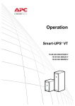
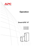
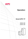
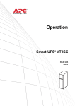
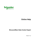
Operation MGE™ Galaxy™ 3500 Series 10-40 kVA 380/400/415 V 10-30 kVA 208/220 V About this Manual This manual is intended for the user of the MGE™ Galaxy™ 3500 series. It refers to important safety warnings and instructions, gives an introduction to the display interface, and provides information on operation, load connection, parts replacement, troubleshooting, total power off and restart. Note: Only graphics of MGE Galaxy 3500 products with built-in batteries are shown in this manual, but the manual is intended for users of one or more units within the MGE Galaxy 3500 series. Most illustrations show 523 mm enclosures but apply to both enclosure sizes. Any differences between the two enclosure sizes will be addressed in the manual. How to find updates to this manual You can check for updates to this manual on www.apc.com. Look for the latest letter revision (A, B ect.) of the manual. : MGE Galaxy 3500 10-40 kVA 380/400/415 V, 10-30 kVA 208/220 V Operation Contents Safety ............................................................................... 1 Overview .......................................................................... 2 User Interface . . . . . . . . . . . . . . . . . . . . . . . . . . . . . . . . . . . . . . . . . . . . 2 Interface area . . . . . . . . . . . . . . . . . . . . . . . . . . . . . . . . . . . . . . . . . . . 2 Display interface . . . . . . . . . . . . . . . . . . . . . . . . . . . . . . . . . . . . . . . . . 2 Menu tree . . . . . . . . . . . . . . . . . . . . . . . . . . . . . . . . . . . . . . . . . . . . . . . 3 Operation ......................................................................... 5 Modes. . . . . . . . . . . . . . . . . . . . . . . . . . . . . . . . . . . . . . . . . . . . . . . . . . . 5 Normal operation . . . . . . . . . . . . . . . . . . . . . . . . . . . . . . . . . . . . . . . . 5 Battery operation . . . . . . . . . . . . . . . . . . . . . . . . . . . . . . . . . . . . . . . . 5 Internal bypass operation . . . . . . . . . . . . . . . . . . . . . . . . . . . . . . . . . 5 External maintenance bypass operation . . . . . . . . . . . . . . . . . . . . . 5 Optional parallel operation . . . . . . . . . . . . . . . . . . . . . . . . . . . . . . . . 5 Single System without External Bypass Panel . . . . . . . . . . . . . . . . . 6 Turn into internal bypass . . . . . . . . . . . . . . . . . . . . . . . . . . . . . . . . . . 6 Turn into normal operation . . . . . . . . . . . . . . . . . . . . . . . . . . . . . . . . 7 Perform a total power off . . . . . . . . . . . . . . . . . . . . . . . . . . . . . . . . . . 8 Perform a restart . . . . . . . . . . . . . . . . . . . . . . . . . . . . . . . . . . . . . . . . . 9 Single System with External Bypass Panel . . . . . . . . . . . . . . . . . . . 10 Turn into external maintenance bypass . . . . . . . . . . . . . . . . . . . . . 10 Turn into normal operation from external maintenance bypass . 11 Perform a total power off . . . . . . . . . . . . . . . . . . . . . . . . . . . . . . . . . 11 Perform a restart . . . . . . . . . . . . . . . . . . . . . . . . . . . . . . . . . . . . . . . . 12 Parallel System . . . . . . . . . . . . . . . . . . . . . . . . . . . . . . . . . . . . . . . . . . 12 Turn into external maintenance bypass . . . . . . . . . . . . . . . . . . . . . 13 Turn into normal operation from external maintenance bypass . 14 Perform a total power off . . . . . . . . . . . . . . . . . . . . . . . . . . . . . . . . . 15 Perform a restart . . . . . . . . . . . . . . . . . . . . . . . . . . . . . . . . . . . . . . . . 15 Isolate one UPS in a parallel system . . . . . . . . . . . . . . . . . . . . . . . 16 Turn the isolated UPS into normal operation . . . . . . . . . . . . . . . . . 16 MGE Galaxy 3500 10-40 kVA 380/400/415 V, 10-30 kVA 208/220 V Operation i Single and Parallel Systems . . . . . . . . . . . . . . . . . . . . . . . . . . . . . . . 17 Turn load off/on via the display interface . . . . . . . . . . . . . . . . . . . . 17 View the Status screens . . . . . . . . . . . . . . . . . . . . . . . . . . . . . . . . . . 18 View Logging . . . . . . . . . . . . . . . . . . . . . . . . . . . . . . . . . . . . . . . . . . . 19 View Statistics . . . . . . . . . . . . . . . . . . . . . . . . . . . . . . . . . . . . . . . . . . 20 Use the Diags screen . . . . . . . . . . . . . . . . . . . . . . . . . . . . . . . . . . . . 20 Configuration ................................................................. 21 Settings . . . . . . . . . . . . . . . . . . . . . . . . . . . . . . . . . . . . . . . . . . . . . . . . 21 Change the Clock and the Alarm thresholds in the Setting menu 21 Change the Beeper setup, the Contrast, and the Language in the Display menu . . . . . . . . . . . . . . . . . . . . . . . . . . . . . . . . . . . . . . . . 23 Maintenance................................................................... 25 Parts Replacement . . . . . . . . . . . . . . . . . . . . . . . . . . . . . . . . . . . . . . . 25 Determine if you need a replacement part . . . . . . . . . . . . . . . . . . . 25 Return parts to APC . . . . . . . . . . . . . . . . . . . . . . . . . . . . . . . . . . . . . 25 Remove the front panel . . . . . . . . . . . . . . . . . . . . . . . . . . . . . . . . . . . 26 Install the front panel . . . . . . . . . . . . . . . . . . . . . . . . . . . . . . . . . . . . 27 Inspect the air filter . . . . . . . . . . . . . . . . . . . . . . . . . . . . . . . . . . . . . . 28 Store the batteries and the UPS system . . . . . . . . . . . . . . . . . . . . . 29 Replace a Network Management Card . . . . . . . . . . . . . . . . . . . . . . . 31 Replace a battery module . . . . . . . . . . . . . . . . . . . . . . . . . . . . . . . . . 31 Troubleshooting ............................................................ 35 Status and Alarm Messages . . . . . . . . . . . . . . . . . . . . . . . . . . . . . . . 35 Display messages . . . . . . . . . . . . . . . . . . . . . . . . . . . . . . . . . . . . . . . 35 ii MGE Galaxy 3500 10-40 kVA 380/400/415 V, 10-30 kVA 208/220 V Operation Safety Warning: All safety instructions in the Safety Sheet (990-2940) must be read, understood and followed prior to handling/using the system. Failure to do so could result in equipment damage, serious injury, or death. Warning: For safety reasons, only qualified personnel is allowed to perform the procedures described under the chapters “Operation” and “Maintenance” . Note: Most illustrations show 523 mm enclosures but apply to both enclosure sizes. Any differences between the two enclosure sizes will be addressed in the manual. MGE Galaxy 3500 10-40 kVA 380/400/415 V, 10-30 kVA 208/220 V Operation 1 Overview User Interface Interface area The four LEDs to the left of the display indicate the operational status of the UPS. The five navigation keys to the right are used to select and open menu items, to access information, change system parameters, and to get context-sensitive help. LOAD ON ON BATT BYPASS Chrg 100% Load 000% 230Vin 000Vout 50Hz Runtime: 00hr 30m FAULT LOAD ON When the green LED is lit, the UPS provides power to the load equipment. ON BATT When the yellow LED is lit, power flows from the batteries to the load. BYPASS When the yellow LED is lit, power to the load is supplied through bypass. FAULT When the red LED is lit, a fault condition exists. LCD SCREEN Displays alarms, status data, instructional help, and configuration items. UP AND DOWN Used to scroll through and select menu items. NAVIGATION KEYS HELP KEY Opens context-sensitive help. ENTER KEY Opens menu items and confirms changes to the system parameters. ESC KEY Returns to the previous screen displayed. Display interface Overview Screen (LCD screen). The Overview Screen is the main entrance to the user functions of the display interface. Overview Screen Chrg 100% Load 000% 230Vin 000Vout 50Hz Runtime: 0hr 0m The ENTER key takes you from the Overview Screen to the Main Screen. 2 MGE Galaxy 3500 10-40 kVA 380/400/415 V, 10-30 kVA 208/220 V Operation Main Screen. From the Main Screen it is possible to command, configure, and monitor the system through the sub menu screens: Control, Status, Setup, Logging, Display, Diags, and Help (see the section “Menu tree” ). Main Screen The selector arrow is controlled by the UP/DOWN keys. The arrow marks the item you may open by pressing ENTER. Control Status Setup Logging Display Diags Help Menu tree Caution: The display provides access to more functions than described in this manual. Those functions should not be accessed without the assistance of APC Customer Support in order to avoid unwanted load impacts. For APC World-Wide Customer Support, refer to the back cover of this manual. If you by accident go beyond the functions described, press ESC to return to previous screens. The menu tree provides a quick overview of the functions and views you may access. MGE Galaxy 3500 10-40 kVA 380/400/415 V, 10-30 kVA 208/220 V Operation 3 If you get beyond the functions described in the menu tree, do not proceed. Press ESC to go back. Control Turn Load Off/On UPS into/out of Bypass Status Vin Vbyp Vout Shutdown Load Default Runtime System Par. redundancy Iin lbyp Iout kW & kVA Frequencies Overview Screen Load & Bat & Temp Batteries Chrg xxx% Load xxx% xxxVin xxxVout xxHz Runtime xxhr Alarms Alarm Thresholds Parallel status Control Display Status Diags Setup Help Logging Clock Other Setup Settings Logging Main Menu Screen View Log Logging Menu View Statistics Language Display Display Setup Contrast Faults and Diagnostics Beeper Setup System Information Int. mech Byp SW Switch Status Q3 External Byp SW Raw Status Data Status from MBP Diags Help 4 On any screen and any line, press ? for context sensitive help MGE Galaxy 3500 10-40 kVA 380/400/415 V, 10-30 kVA 208/220 V Operation Operation Warning: For safety reasons, only qualified personnel is allowed to perform the operation procedures described in this chapter. Modes The UPS has different operation modes. If the installation includes a Maintenance Bypass Panel (MBP), an external maintenance bypass operation mode will also be available. Normal operation The UPS converts utility/mains power to conditioned power for the connected load. Battery operation The UPS provides power to the connected load from its internal and (if available) external batteries for a finite period. The UPS transfers to battery operation if the supply of utility/mains power fails, or is outside the pre-defined limits. Internal bypass operation Internal bypass keeps the load supplied with utility/mains power during maintenance of the UPS power sections. In internal bypass operation, utility/mains power is sent directly to the connected load bypassing all internal UPS functions and filters. Battery back-up is not available in internal bypass operation even though the batteries are in place. External maintenance bypass operation The UPS can be connected to an optional external MBP. When activated, this panel bypasses the entire UPS enclosure, feeding utility/mains power directly to the load. An activated external MBP completely isolates the UPS and allows maintenance to be performed. An external MBP is mandatory if the UPS is running in parallel. Optional parallel operation The connected load is powered by multiple UPS units to increase system redundancy or to increase power. The internal mechanical bypass lever is not available. MGE Galaxy 3500 10-40 kVA 380/400/415 V, 10-30 kVA 208/220 V Operation 5 Single System without External Bypass Panel Warning: For safety reasons, only qualified personnel is allowed to perform the operation procedures described in this chapter. Turn into internal bypass Warning: In bypass operation the batteries are still powered. If a total power off is required, the load must be off, and the batteries must be pulled out to the red disconnect line, see the section “Perform a total power off” on page 8. Caution: The load is not protected by the UPS and the power is not conditioned when the internal mechanical bypass lever is activated. Note: This procedure is not applicable to parallel systems as the internal mechanical bypass lever is unavailable. 1. If the UPS is running and controllable through the display, carry out steps 1-5. If not, go directly to step 6. 2. From the Overview Screen, press ENTER. Chrg 100% Load 000% xxxVin 000Vout x0Hz Runtime: 0hr 0m 3. Go to Control by using the UP/DOWN navigation keys and press ENTER. 4. Go to UPS into Bypass by using the UP/ DOWN Use Use navigation keys and press ENTER. 5. Go to YES, UPS into Bypass by using the UP/DOWN navigation keys and press ENTER. 6. Check that the UPS is in bypass. The green (LOAD ON) and the yellow (BYPASS) LEDs are illuminated. Use Control Status Setup Logging Display Diags Help UPS into Bypass Do Self Test Simulate Power Fail Start Runtime Cal Confirm: UPS into Bypass NO, ABORT YES, UPS into Bypass Press Press Press Press Warning: For safety reasons, only qualified personnel is allowed to perform the following steps. 7. Remove the front panel from the UPS (see “Remove the front panel” on page 26). 6 MGE Galaxy 3500 10-40 kVA 380/400/415 V, 10-30 kVA 208/220 V Operation 8. Turn the internal mechanical bypass lever upwards to activate it. The load will now be supported directly by utility/mains power. 9. Reinstall the front panel. Turn into normal operation Caution: Never attempt to switch back the UPS into normal operation till you have verified that there are no internal UPS faults. 1. Check that the UPS is in bypass. The green (LOAD ON) and the yellow (BYPASS) LEDs are illuminated. 2. Turn the mechanical bypass lever downwards into a horizontal position to deactivate the internal bypass operation. 3. If the UPS has not returned to normal operation: Press ESC to return to the previous menus and turn out of bypass from the display via Control > UPS out of bypass > Yes, UPS out of bypass. 4. Check that the UPS is in normal operation. The yellow (BYPASS) LED turns off and the green (LOAD ON) LED remains illuminated. MGE Galaxy 3500 10-40 kVA 380/400/415 V, 10-30 kVA 208/220 V Operation 7 Perform a total power off Note: In order to carry out this procedure the load supported by the UPS must be turned off. Mains breaker UPS XR Enclosure 1. Check that the load which is supported by the UPS is turned OFF. 2. From the UPS: Turn load OFF from the display via Control > Turn Load Off > Yes, Turn Load Off. 3. From the XR Enclosure(s) (if available): Set the DC disconnect switch(es) to position OFF. 4. From the UPS: Disconnect the batteries by pulling them out to the red disconnect line shown on each battery unit. 5. From the XR Enclosure(s) (if available): Disconnect the batteries by pulling them out to the red disconnect line shown on each battery unit. 6. Set the utility/mains breaker to position OFF or LOCKED-OUT. If the UPS has dual utility/mains supply, set both supplies to position OFF or LOCKED-OUT. Warning: The lockout procedures at the utility/mains breaker must be followed. If necessary, install a padlock. For details on how to remove Battery Locks (if available) see the section “Replace a battery module” and hereunder “Remove and install battery locks (if available)” on page 32. 8 MGE Galaxy 3500 10-40 kVA 380/400/415 V, 10-30 kVA 208/220 V Operation Perform a restart Warning: Only qualified personnel familiar with the construction and the equipment may restart the UPS. 1. Set the utility/mains breaker to position ON. 2. If your installation includes an XR Battery Enclosure with a DC disconnect switch, set the DC disconnect switch to position ON. Note: Wait approximately 30 seconds for the system to boot up and carry out a self test. After system boot-up, the display will automatically ask you to confirm/select voltage and frequency as shown in the following. Voltage confirmation. At restart, the display will prompt you through the following screens: 1. When the Confirm Voltage prompt appears on the screen, go to the desired voltage using the UP/DOWN navigation keys and press ENTER. 2. When the prompt Apply load appears, go to Yes using the UP/DOWN navigation keys and press ENTER if you want the UPS to provide a load output now. (If you do not want a UPS load output at this point, go to No). 3. The green (LOAD ON) LED is now lit. Press ESC two times and the display will show the above Overview Screen. Use Use Confirm Voltage Use 400V Yes, use 400V No, select another Apply load? Yes No Press Press Chrg xxx% |||||||||| Load xxx% |||||||||| xxx Vin xxxVout xxHz Runtime: xxhr xxmin Note: The UPS is now ready to support the load. Note: Auto-detection on frequency – if a problem occurs call APC Customer Support (see the back cover of this manual). MGE Galaxy 3500 10-40 kVA 380/400/415 V, 10-30 kVA 208/220 V Operation 9 Single System with External Bypass Panel Warning: For safety reasons, only qualified personnel is allowed to perform the operation procedures described in this chapter. Turn into external maintenance bypass Warning: In bypass operation the batteries are still powered. If a total power off is required the load must be off and the batteries must be pulled out to the red disconnect line, see the section “Perform a total power off” on page 11. 1. From the Overview Screen, press ENTER. Chrg 100% Load 000% xxxVin 000Vout x0Hz Runtime: 0hr 0m 2. Go to Control by using the UP/DOWN navigation keys and press ENTER. Use 3. Go to UPS into Bypass by using the UP/DOWN navigation keys and press ENTER. Use 4. Go to YES, UPS into Bypass by using the UP/ DOWN navigation keys and press ENTER. Use 5. From the external Maintenance Bypass Panel (MBP): Turn the bypass switch (Q3) to position “|” (ON). Control Status Setup Logging Display Diags Help UPS into Bypass Do Self Test Simulate Power Fail Start Runtime Cal Confirm: UPS into Bypass NO, ABORT YES, UPS into Bypass Press Press Press Press 6. From the external MBP: Turn the output switch (Q2) to position “O” (OFF). Now the load is not supported by the UPS. Note! If you need to turn the UPS completely OFF, proceed with steps 7–11. 7. If you need to turn the UPS completely OFF: From the external MBP: Turn the input switch (Q1) to position “O” (OFF). 8. From the XR Enclosure(s) (if available): Set the DC disconnect switch(es) to position OFF. 9. From the UPS: Disconnect the batteries by pulling them out to the red disconnect line shown on each battery unit. 10.From the XR Enclosure(s) (if available): Disconnect the batteries by pulling them out to the red disconnect line shown on each battery unit. 10 MGE Galaxy 3500 10-40 kVA 380/400/415 V, 10-30 kVA 208/220 V Operation Turn into normal operation from external maintenance bypass Caution: Never attempt to switch back the UPS into normal operation till you have verified that there are no internal UPS faults. 1. If the UPS has been completely turned OFF, proceed with steps 2–10. If the UPS has not been completely turned OFF, proceed with steps 6–10. 2. From the XR Enclosure(s) (if available): Connect the batteries by pushing them in. 3. From the UPS: Connect the batteries by pushing them in. 4. From the XR Enclosure(s) (if available): Set the DC disconnect switch(es) to position ON. 5. From the external MBP: Turn the input switch (Q1) to position “|” (ON). 6. From the external MBP: Turn the output switch (Q2) to position “|” (ON). Now the load is supported by the UPS. 7. From the UPS: Check that the yellow (BYPASS) LED is illuminated and the green (LOAD ON) LED is illuminated. 8. From the external MBP: Turn the bypass switch (Q3) to position “O” (OFF). 9. If the UPS has not returned to normal: From the UPS: Turn out of bypass from the display via Control > UPS out of bypass > Yes, UPS out of bypass. 10.From the UPS: Check that the UPS is in normal operation. The yellow (BYPASS) LED turns off and the green (LOAD ON) LED remains illuminated. Perform a total power off Note: In order to carry out this procedure the load supported by the UPS must be turned off. 1. Check that the load which is supported by the UPS is turned OFF. 2. From the UPS: Turn load OFF from the display via Control > Turn Load Off > Yes, Turn Load Off. 3. From the external MBP: Turn the output switch (Q2) to position “O” (OFF). 4. From the external MBP: Turn the input switch (Q1) to position “O” (OFF). 5. From the XR Enclosure(s) (if available): Set the DC disconnect switch to position OFF. 6. From the UPS: Disconnect the batteries by pulling them out to the red disconnect line shown on each battery unit. 7. From the XR Enclosure(s) (if available): Disconnect the batteries by pulling them out to the red disconnect line shown on each battery unit. MGE Galaxy 3500 10-40 kVA 380/400/415 V, 10-30 kVA 208/220 V Operation 11 Perform a restart Warning: Only qualified personnel familiar with the construction and the equipment may restart the UPS. 1. From the XR Enclosure(s) (if available): Connect the batteries by pushing them in. 2. From the UPS: Connect the batteries by pushing them in. 3. From the XR Enclosure(s) (if available): Set the DC disconnect switch(es) to position ON. 4. From the external MBP: Turn the input switch (Q1) to position “|” (ON). 5. From the external MBP: Turn the output switch (Q2) to position “|” (ON). 6. From the UPS: Turn load ON from the display via Control > Turn Load On > Yes, Turn Load On. 7. Check that the load is ON. Note: The UPS is now ready to support the load. Note: Auto-detection on frequency – if a problem occurs call APC Customer Support (see the back cover of this manual). Parallel System Warning: For safety reasons, only qualified personnel is allowed to perform the operation procedures described in this chapter. Warning: Parallel Operation is not available for the 3:1 version of MGE Galaxy 3500. 12 MGE Galaxy 3500 10-40 kVA 380/400/415 V, 10-30 kVA 208/220 V Operation Turn into external maintenance bypass Warning: In bypass operation the batteries are still charged. If a total power off is required, the load must be off and the batteries must be pulled out to the red disconnect line, see the section “Perform a total power off” on page 14. 1. From the Overview Screen, press ENTER. Chrg 100% Load 000% xxxVin 000Vout x0Hz Runtime: 0hr 0m 2. Go to Control by using the UP/DOWN navigation keys and press ENTER. Use 3. Go to UPS into Bypass by using the UP/ DOWN navigation keys and press ENTER. Use 4. Go to YES, UPS into Bypass by using the UP/DOWN navigation keys and press ENTER. Use 5. From the UPS: Check that all UPS units are in bypass on each of the displays. The yellow bypass LED is illuminated on each UPS unit. Control Status Setup Logging Display Diags Help UPS into Bypass Do Self Test Simulate Power Fail Start Runtime Cal Confirm: UPS into Bypass NO, ABORT YES, UPS into Bypass Press Press Press Press 6. From the external Maintenance Bypass Panel (MBP): Check that the bypass lamp indicator (Q3) is illuminated at Q3. 7. From the external MBP: Turn the bypass switch (Q3) to position “|” (ON). 8. From the external MBP: Check that the lamp indicator of the output isolation breaker (H4) at Q4 is illuminated. 9. From the external MBP: Turn the output isolation breaker (Q4) to position “O” (OFF). The UPS is now in external maintenance bypass with the batteries still powered. Note! If you need to turn the UPS units completely OFF, proceed with steps 11–18. 10.From the UPS: Turn OFF each UPS unit from the display via Control > Turn Load Off > Yes, Turn Load Off. 11. From the external MBP: Check that all the output lamps (UPS 1, UPS2, UPS3) at Q2 are illuminated. 12.From the external MBP: Turn all output switches (Q2) to position “O” (OFF). 13.From the XR Enclosure(s) (if available): Set the DC disconnect switch(es) to position OFF. 14.From the UPS: Disconnect the batteries by pulling them out to the red disconnect line shown on each battery unit. 15.From the XR Enclosure(s) (if available): Disconnect the batteries by pulling them out to the red disconnect line shown on each battery unit. MGE Galaxy 3500 10-40 kVA 380/400/415 V, 10-30 kVA 208/220 V Operation 13 Turn into normal operation from external maintenance bypass Caution: Never attempt to turn the UPS into normal operation till you have verified that there are no internal UPS faults. 1. If the UPS units have been completely turned OFF, proceed with steps 2–16. If the UPS units have not been completely turned OFF, proceed with step 13–16. 2. From the UPS: Connect the batteries in each UPS by pushing them in. 3. From the XR Enclosure(s) (if available): Connect the batteries in each UPS by pushing them in. 4. From the XR Enclosure(s) (if available): Set the DC disconnect switch(es) to position ON. 5. From the external MBP: Turn all input switches (Q1) to position “|” (ON). 6. From the external MBP: Check that all the output lamps (UPS1, UPS2, UPS3) at Q2 are illuminated. 7. From the external MBP: Turn all output switches (Q2) to position “|” (ON). The lamp indicator of the output isolation breaker (Q4) is still illuminated. 8. From the UPS: Turn ON all UPS units from each display via Control > Turn Load ON > Yes, Turn Load ON. The green online LEDs are illuminated on each UPS unit. 9. From the external MBP: Check that all the output lamps (UPS1, UPS2, UPS3) at Q4 are not illuminated. 10.From the UPS: Turn the UPS units into bypass from one UPS display via Control > UPS into bypass > Yes, UPS into bypass. Check that the UPS units are in bypass. The green (LOAD ON) and the yellow (BYPASS) LEDs are illuminated. 11. From the external MBP: Check that the lamp indicator of the output isolation breaker (Q4) is illuminated. 12.From the external MBP: Turn the output isolation breaker (Q4) to position “|” (ON). Now the lamps Q3 + Q4 are illuminated. 13.From the external MBP: Turn the bypass switch (Q3) to position “O” (OFF). The lamp indicator of the output isolation breaker (Q4) at Q4 is not illuminated, but the bypass lamp (Q3) at Q3 is illuminated, until the UPS is running in normal operation. 14.From the UPS: Turn the UPS units out of bypass from the display via Control > UPS out of bypass > Yes, UPS out of bypass. Perform a total power off Note: In order to carry out this procedure the load supported by the UPS must be turned off. 1. Check that the load which is supported by the UPS is turned OFF. 2. From the UPS: Turn load OFF from each of the UPS displays via Control > Turn Load Off > Yes, Turn Load Off. 3. From the external MBP: Turn the output isolation breaker (Q4) to position “O” (OFF). 4. From the external MBP: Turn all output switches (Q2) to position “O” (OFF). 5. From the XR Enclosure(s) (if available): Set the DC disconnect switch(es) to position OFF. 6. From the XR Enclosure(s) (if available): Disconnect the batteries on the UPS units by pulling them out to the red disconnect line shown on each battery unit. 14 MGE Galaxy 3500 10-40 kVA 380/400/415 V, 10-30 kVA 208/220 V Operation Perform a restart Warning: Only qualified personnel familiar with the construction and the equipment may restart the UPS system. 1. From the XR Enclosure(s) (if available): Connect the batteries by pushing them in. 2. From the UPS: Connect the batteries by pushing them in. 3. From the XR Enclosure(s) (if available): Set the DC disconnect switch(es) to position ON. 4. From the external MBP: Turn all output switches (Q2) to position “|” (ON). 5. From the external MBP: Turn the output isolation breaker (Q4) to position “|” (ON). 6. From the UPS: Turn load ON from the display of each UPS via Control > Turn Load On > Yes, Turn Load On. 7. Check that the load is ON. Note: The UPS system is now ready to support the load. Note: Auto-detection on frequency – if a problem occurs call APC Customer Support (see the back cover of this manual). Isolate one UPS in a parallel system 1. From the UPS: From the Main screen select Status and scroll down to Status of actual redundancy: n+ in order to check that the remaining UPS(s) will be able to support the load when one UPS is isolated. 2. From the UPS: Turn load OFF (from the display on the UPS to be isolated) via Control > Turn Load Off > Yes, Turn Load Off. 3. From the external MBP: Check that the output lamp (Q2) at Q2 (of the UPS to be isolated) is illuminated. 4. From the external MBP: Turn the output switch (Q2) (of the UPS to be isolated) to position “O” (OFF). 5. From the XR Enclosure(s) (if available): Set the DC disconnect switch(es) to position OFF. 6. From the UPS: Disconnect the batteries in the UPS to be isolated by pulling them out to the red disconnect line shown on each battery unit. 7. From the XR Enclosure(s) (if available): Disconnect the batteries by pulling them out to the red disconnect line shown on each battery unit. MGE Galaxy 3500 10-40 kVA 380/400/415 V, 10-30 kVA 208/220 V Operation 15 Turn the isolated UPS into normal operation 1. From the XR Enclosure(s) (if available): Connect the batteries by pushing them in. 2. From the UPS: Connect the batteries by pushing them in. 3. From the XR Enclosure(s) (if available): Set the DC disconnect switch(es) to position ON. 4. From the external MBP: Check that the output lamp (Q2) at Q2 (of the UPS to be turned into normal operation) is illuminated. 5. From the external MBP: Turn the output switch (Q2) (of the UPS to be turned into normal operation) to position “|” (ON) . 6. From the UPS: Turn load ON (from the display on the UPS to be turned into normal operation) via Control > Turn Load on > Yes, turn Load on. 7. From the UPS: Press ESC two times to get back to the Overview Screen. 8. From the UPS: On each Overview Screen, check that the load percentage of the UPS units is approximately the same. 16 MGE Galaxy 3500 10-40 kVA 380/400/415 V, 10-30 kVA 208/220 V Operation Single and Parallel Systems Turn load off/on via the display interface Warning: Disconnecting the UPS output to the load does NOT de-energize the UPS! Always follow the total power off procedure if you need to de-energize the UPS in emergency situations, see the section Perform a total power off under respectively “Single System without External Bypass Panel” on page 6, “Single System with External Bypass Panel” on page 10 and “Parallel System” on page 12. Turn Load off – Disconnect the UPS output to the load equipment. 1. From the Overview Screen, press ENTER. Chrg 100% Load 000% xxxVin 000Vout x0Hz Runtime: 0hr 0m 2. Go to Control by using the UP/DOWN navigation keys and press ENTER. Use 3. Go to Turn Load Off by using the UP/ DOWN navigation keys and press ENTER. Use 4. Go to YES, Turn Load OFF by using the UP/DOWN navigation keys and press ENTER. Use 5. If the UPS is running in parallel operation this procedure must be carried out on each UPS. Control Status Setup Logging Display Diags Help Turn Load Off Confirm: Turn Load OFF NO, Abort YES, Turn Load OFF MGE Galaxy 3500 10-40 kVA 380/400/415 V, 10-30 kVA 208/220 V Operation Press Press Press Press 17 Turn load on – Connect the UPS output to the load equipment. 1. From the Overview Screen, press ENTER. Chrg 100% Load 000% xxxVin 000Vout x0Hz Runtime: 0hr 0m 2. Go to Control by using the UP/DOWN navigation keys and press ENTER. Use 3. Go to Turn Load On by using the UP/ DOWN navigation keys and press ENTER. Use 4. Go to YES, Turn Load ON by using the UP/DOWN navigation keys and press ENTER. Use 5. If the UPS is running in parallel operation this procedure must be carried out on each UPS. Control Status Setup Logging Display Diags Help Press Press Press Turn Load On Confirm: Turn Load OFF NO, Abort YES, Turn Load ON Press View the Status screens 1. From the Overview Screen, press ENTER. Chrg 100% Load 000% xxxVin 000Vout x0Hz Runtime: 0hr 0m 2. Go to Status by using the UP/DOWN navigation keys and press ENTER. 3. Use the UP/DOWN keys to go through the below parameters and press the ESC key to return to the previous menus. View 18 Use Control Status Setup Logging Display Diags Help Press Press Parameters Voltage on all phases Utility/mains voltage (V), bypass voltage (V), and output voltage (V) for each phase. Current on all phases Utility/mains current (A), bypass current (A), and output current (A) for each phase. kVA and kW Apparent power (kVA) and real power (kW) generated by the UPS and the connected load. Frequencies Utility/mains frequency, bypass frequency, and output frequency in Hertz (Hz). Load and batteries Load: Percentage of the load in relation to the total UPS capacity. MGE Galaxy 3500 10-40 kVA 380/400/415 V, 10-30 kVA 208/220 V Operation View Parameters Bat Voltage Shows either the positive or negative half of the battery voltage (the lower value of the two will appear). Bat Cap Percentage charge on the batteries in relation to the total battery capacity. Runtime: The predicted runtime at the present load. Batteries Bat AmpHr: Battery capacity, including both external and internal batteries. UPS Temp: The highest external battery temperature. Alarm thresholds Load: An alarm will be set when the load is above the threshold level. Runtime: An alarm will be set when the runtime is below the threshold level. Parallel Status Local UPS is slave/master: # of UPSs OK: Indicates the number of parallel UPS units that is OK. # of UPSs fail: Indicates the number of parallel UPS that has failed. Par load Status KVA and KW: Total apparent power (kVA) and real power (kW) generated by the parallel UPS units and the connected load. Par redundancy: n+1, an alarm will be set if the redundancy level is below the threshold level. Parallel Operation Mode The parallel operation mode can be off, load on, requested bypass, in bypass due to fault or maintenance. View Logging View the 100 most recent UPS log events, and view the logged details of the events, such as date, time of occurrence, and event number. 1. From the Overview Screen, press ENTER. Chrg 100% Load 000% xxxVin 000Vout x0Hz Runtime: 0hr 0m 2. Go to Logging by using the UP/DOWN navigation keys and press ENTER. Use 3. Go to View Log by using the UP/DOWN navigation keys and press ENTER. Use 4. Go to On Line by using the UP/DOWN navigation keys and press ENTER. Use Control Status Setup Logging Display Diags Help View log Clear log View statistics 24-Sep 15:06:48 #15 Mains out of Range On Line =================== Press Press Press Press 5. The top line states date, time, and event number. Lines 2, 3, and 4 are part of the Logging Screen (example) event list. To view the entire list: Use the UP/ DOWN keys to go through the log events and press ENTER to get a detailed description of a particular event. MGE Galaxy 3500 10-40 kVA 380/400/415 V, 10-30 kVA 208/220 V Operation 19 View Statistics View the statistics on the operation mode changes, the inverter time, and the duration of battery operation. 1. From the Overview Screen, press ENTER. Chrg 100% Load 000% xxxVin 000Vout x0Hz Runtime: 0hr 0m 2. Go to Logging by using the UP/DOWN navigation keys and press ENTER. Use 3. Go to View Statistics by using the UP/ DOWN navigation keys and press ENTER. Use Control Status Setup Logging Display Diags Help View log Clear log View statistics =================== Press Press Press Logging Screen Use the Diags screen View troubleshooting information. 1. From the Overview Screen, press ENTER. Chrg 100% Load 000% xxxVin 000Vout x0Hz Runtime: 0hr 0m 2. Go to Diags by using the UP/DOWN navigation keys and press ENTER. Use 3. Go to Fault & Diagnostics by using the UP/ DOWN navigation keys and press ENTER. Use Control Status Setup Logging Display Diags Help Fault & Diagnostics System Information Switch status Raw Status Dump Diags Screen Note: For more details on the Fault and Diagnostics screens, see the section “Troubleshooting” on page 35. 20 MGE Galaxy 3500 10-40 kVA 380/400/415 V, 10-30 kVA 208/220 V Operation Press Press Press Configuration Settings Change the Clock and the Alarm thresholds in the Setting menu Chrg xxx% Load xxx% xxxxVin Runtime Clock Load Alarms Runtime Shutdown Par. Redundancy Default System Control Display Status Diags Setup Help Logging Setup Settings Other Clock. The Clock menu changes the date and the clock settings and it time-stamps events in the event log. To avoid inaccuracies, change the clock-setting at daylight-saving time. 1. From the Overview Screen, press ENTER. Chrg 100% Load 000% xxxVin 000Vout x0Hz Runtime: 0hr 0m 2. Go to Setup by using the UP/DOWN navigation keys and press ENTER. Use 3. Go to Clock by using the UP/DOWN navigation keys and press ENTER. Use Control Status Setup Logging Display Diags Help Settings: Shutdown Default System Press Press Alarms Clock Other 4. Press ENTER. Date: 24-Sep-2006 Time: 13:45:51 MGE Galaxy 3500 10-40 kVA 380/400/415 V, 10-30 kVA 208/220 V Operation Press Press 21 5. The day is now active. Use the UP/DOWN navigation keys to set the date and press ENTER. 6. The month is now active. Use the UP/DOWN navigation keys to set the month, press ENTER and do the same to set the year, and press ENTER. 7. Press the DOWN navigation key to activate the Time line. 8. The procedure to change the Time features is the same as described for date and month. Change date Use Use Use Date: 24-Sep-2006 Time: 13:45:51 Change month Date: 24-Sep-2006 Time: 13:45:51 Date: 24-Sep-2006 Time: 13:45:51 Press Press Press Press to return to previous screen(s) Alarm thresholds. The procedure for changing the Alarm thresholds is the same as described under the Clock changes. Be aware of the below notes. Note: If the load level exceeds the pre-programmed threshold, the UPS will display a warning. Note: Redundancy: The state of redundancy that will trigger an alarm: Choices are: • N+0 – The power requirement exceeds the redundancy limit: Redundancy is not available. • N+1 – The power requirement does not utilize the last unit: Redundancy is available. • N+2 – The power requirement does not utilize the last two units: Redundancy is available. • N+3 – The power requirement does not utilize the last three units: Redundancy is available. 22 MGE Galaxy 3500 10-40 kVA 380/400/415 V, 10-30 kVA 208/220 V Operation Change the Beeper setup, the Contrast, and the Language in the Display menu Chrg xxx% Load xxx% xxxxVin Runtime Control Display Status Diags Setup Help Logging Beeper setup Display Display setup Contrast Language Work your way through the menu screens and make your changes with the UP/DOWN and the ENTER keys as described for the Clock and the Alarms in the Settings menu. The Beeper setup. In the Beeper setup you can choose between the following options: • Never: If you select this setting, the beeper will be active at internal UPS errors only. • PwrFail+30: If you select this setting, the beeper will be active at internal UPS errors and at utility/mains or bypass errors. The beeper will only sound if the fault has been present for more than 30 seconds. • PwrFail: If you select this setting, the beeper will be active at internal UPS errors and at utility/ mains or bypass errors. The beeper will sound immediately when the error is occurring. • LOW BATT: If you select this setting, the beeper will be active at internal UPS errors at utility/ mains or bypass errors, at power failures, and at a low battery level (if the UPS runs in battery operation). MGE Galaxy 3500 10-40 kVA 380/400/415 V, 10-30 kVA 208/220 V Operation 23 Maintenance Warning: For safety reasons, only qualified personnel is allowed to perform the replacement procedures described in this chapter. Parts Replacement Determine if you need a replacement part To determine if you need a replacement part, contact APC Customer Support and follow the procedure below so that the APC Customer Support representative can assist you promptly: 1. In the event of a module failure, the display interface may show additional “fault list” screens. Press any key to scroll through these fault lists, record the information, and provide it to the representative. 2. Write down the serial number of the unit so that you will have it easily accessible when you contact APC Customer Support. 3. If possible, call APC Customer Support from a telephone that is within reach of the UPS display interface so that you can gather and report additional information to the representative. 4. Be prepared to provide a detailed description of the problem. A representative will help you solve the problem over the telephone, if possible, or will assign a Return Material Authorization (RMA) number to you. If a module is returned to APC, this RMA number must be clearly printed on the outside of the package. 5. If the unit is within the warranty period, repairs or replacements will be performed free of charge. If it is not within the warranty period, there will be a charge. 6. If the unit is covered by an APC service contract, have the contract available to provide information to the representative. Return parts to APC Call APC Customer Support to obtain an RMA number. To return a failed module to APC, pack the module in the original shipping materials, and return it by insured, prepaid carrier. The APC Customer Support representative will provide the destination address. If you no longer have the original shipping materials, ask the representative about obtaining a new set. Pack the module properly to avoid damage in transit. Never use styrofoam beads or other loose packaging materials when shipping a module, as the module may settle in transit and become damaged. Enclose a letter in the package with your name, RMA number, address, a copy of the sales receipt, description of the problem, a phone number, and a check as payment (if necessary). Note: Damages sustained in transit are not covered under warranty. MGE Galaxy 3500 10-40 kVA 380/400/415 V, 10-30 kVA 208/220 V Operation 25 Remove the front panel Serial: Model: BATTER Y UNIT Serial: Model: BATTER Y UNIT Serial: Model: BATTER Y UNIT Serial: Model: BATTER Y UNIT Serial: Model: BATTER Y UNIT Serial: Model: BATTER Y UNIT Serial: Model: BATTER Y UNIT Serial: Model: BATTER Y UNIT 1. Use a coin or similar to turn the two black lock devices on either side of the display in the direction of each other to a vertical position. 2. Push the front panel upwards and pull it outwards to disengage the locking device at the top of the enclosure. 3. Lift the front panel free of the two slots at the bottom of the enclosure. 26 MGE Galaxy 3500 10-40 kVA 380/400/415 V, 10-30 kVA 208/220 V Operation Install the front panel Serial: Model: BATTER Y UNIT Serial: Model: BATTER Y UNIT Serial: Model: BATTER Y UNIT Serial: Model: BATTER Y UNIT Serial: Model: BATTER Y UNIT Serial: Model: BATTER Y UNIT Serial: Model: BATTER Y UNIT Serial: Model: BATTER Y UNIT 1. Insert the two guide taps at the bottom of the front panel into the two slots at the bottom of the enclosure. 2. Push the front panel against the enclosure to engage the locking device at the top of the enclosure. 3. Turn the two black lock devices away from the display to a horizontal level by using a coin or a similar tool. MGE Galaxy 3500 10-40 kVA 380/400/415 V, 10-30 kVA 208/220 V Operation 27 Inspect the air filter The UPS and XR Enclosure front panels are fitted with air filters on the inside of the front panels for extra protection of systems installed in environments with conductive dust. Check the air filters once a month. If the air filters show visible dust or other impurities, the air filters must be replaced. Serial: Model: BATTERY UNIT Serial: Model: BATTERY UNIT Serial: Model: BATTERY UNIT Serial: Model: BATTERY UNIT Serial: Model: BATTERY UNIT Serial: Model: BATTERY 12 pcs UNIT Serial: Model: BATTERY UNIT Serial: Model: BATTERY UNIT 1. Remove the front panel from the enclosure. See “Remove the front panel” on page 26. 2. Remove the wing nuts from the plate between the upper and lower air filter. 3. Remove the plate. 28 MGE Galaxy 3500 10-40 kVA 380/400/415 V, 10-30 kVA 208/220 V Operation 4. Push the top air filter downwards, and pull outwards to remove. 5. Pull the lower air filter outwards, and push upwards to remove. 6. Position the new air filters and make sure that the metal side of the air filters face outwards. 7. Remount the plate between the upper and lower air filters and reattach the two wing nuts. 8. Reinstall the front panel. Store the batteries and the UPS system Note: The battery modules must be stored indoors and with their protective packaging still in place. Note: Stored batteries should be recharged at regular intervals, depending on the storage temperature: Ambient temperature: -15° to 40°C/5°F to 104°F Relative humidity: 25-85% Non-condensing Storage place free from vibration, dust, direct sunlight, and moisture. Storage Temperature Recharge Interval -15° to 20°C/5°F to 68°F 9 months 20° to 30°C/68°F to 86°F 6 months 30° to 40°C/86°F to 104°F 3 months Caution: Do not store the batteries for more than 12 months. User- replaceable parts (only qualified personnel). Part APC Part Nos. Battery Module SYBT4 Network Management Card with temperature sensor AP9631 Airfilter for 352mm enclosures G35TOPT1 Air filter for 523mm enclosures G35TOPT2 Note: APC recommends that a whole battery module (four batteries) is replaced at the same time to ensure optimal runtime. However, it is only necessary to replace two batteries at the same time. See the section “Directions for replacement” on page 33. MGE Galaxy 3500 10-40 kVA 380/400/415 V, 10-30 kVA 208/220 V Operation 29 User interface (front). Network Management Card with temperature sensor: used for remote system control and monitoring, e-mail notifications etc. For configuration and use, refer to the separate user manual: Network Management Card with Environmental Monitor – shipped with the UPS. Computer-interface port for the connection of computers with APC Powerchute® software. Internal mechanical bypass lever: used to bypass the upstream utility/mains power around the UPS to support the load directly = internal bypass operation. Not applicable in parallel systems. Service port (for APC maintenance personnel only). Display port for the connection of display communication cable. Parallel operation port. Documentation storage. Power module. 30 MGE Galaxy 3500 10-40 kVA 380/400/415 V, 10-30 kVA 208/220 V Operation Replace a Network Management Card 1. Loosen the two Torx screws (one on each side of the card). 2. Carefully pull out the card. 3. Install the new card. 4. Reattach the two Torx screws. Replace a battery module General safety prior to battery module replacement. Note: When replacing battery modules, replace with same part number. Caution: Batteries must be replaced by qualified personnel only. Caution: Servicing of batteries should be performed or supervised by personnel knowledgeable of batteries and the required precautions. Keep unauthorized personnel away from batteries. Do not dispose of battery or batteries in a fire. The battery may explode. Do not open or multilate the battery or batteries. Released electrolyte is harmful to the skin and eyes. It may be toxic. A battery can present a risk of electrical shock and high short circuit current. The following precautions should be observed when working on batteries: • Remove watches, rings, or other metal objects. • Use tools with insulated handles. • Wear rubber gloves and boots. • Do not lay tools or metal parts on top of batteries. • Disconnect charging source prior to connecting or disconnecting battery terminals. MGE Galaxy 3500 10-40 kVA 380/400/415 V, 10-30 kVA 208/220 V Operation 31 Heavy: Use two people to lift components weighing between 18–32 kg/40–70 lb. Battery Module. One battery module consists of four battery units (shipping in the enclosures). 4 x 24 kg/4 x 53 lbs Remove and install battery locks (if available). If your system is equipped with battery locks, follow the below procedure to remove the battery locks. 1. Remove the M6 screw attaching the battery lock to the shelf. 2. Push the battery lock to the left, push it upwards and remove. 3. Use the reverse procedure for the installation of battery locks. . Replacement. Caution: Batteries must be replaced by qualified personnel only (see the section “General safety prior to battery module replacement” on page 31). 32 MGE Galaxy 3500 10-40 kVA 380/400/415 V, 10-30 kVA 208/220 V Operation Directions for replacement. APC recommends that a whole battery module (four batteries) is replaced at the same time to ensure optimal runtime (see Example 1). However, it is only necessary to replace two batteries at the same time according to Example 2 and 3 in the below tables. 523 mm/(20.59 in) Enclosure Column A Column B Column C Column D Example 1 New New New New Example 2 New New Old Old Example 3 Old Old New New Column A Column B New New New New New New Old Old Old Old New New 352 mm/(14 in) Enclosure Example 1 Example 2 Example 3 Follow the below procedures if you need to change or add a battery module, e.g. if you receive a display message reporting a bad battery, or if you need to add batteries for increased runtime. XR UPS MGE Galaxy 3500 10-40 kVA 380/400/415 V, 10-30 kVA 208/220 V Operation 33 1. When removing battery modules, start from the highest level and work down. 2. Holding the battery handle, gently push the battery upwards and pull it halfway out of the enclosure. A lock mechanism prevents it from being pulled all the way out. 3. To release the battery from the lock mechanism, gently push the battery upwards again and pull it out, while another person supports the battery. Installation. If additional batteries are needed for extra runtime, or if you install battery replacement modules, be aware of the following: Caution: Do not install battery modules in the UPS until you are ready to power up the system. Disregarding this caution can result in a deep discharge of the batteries and cause permanent damage. The time between battery installation and powering up the UPS should not exceed 72 hours/ three days. UPS / XR 1. Install the battery module in the lowest available bay (four across in 523 mm/(20 in) UPS versions, two across in 352 mm/(14 in) UPS versions). 2. Position the battery unit to slide in between the grooves and push it completely into the UPS to ensure connection. Note: If a problem is reported, ensure that the modules in question are correctly installed. If the problem persists, see the section “Troubleshooting” on page 35. Note: Allow for a 24-hour recharging period of the batteries after system start-up. 34 MGE Galaxy 3500 10-40 kVA 380/400/415 V, 10-30 kVA 208/220 V Operation Troubleshooting Status and Alarm Messages This section lists the status and alarm messages that the UPS might display. The messages are listed in alphabetical order, and a suggested corrective action is listed with each alarm message to help you troubleshoot problems. Display messages Display Message Meaning Corrective Action Automatic Self Test Started. The UPS has started preprogrammed battery test. No corrective action is necessary. ABus Communication Fault. Communication fault detected on the ABus. Check ABus wiring. If this does not help contact APC. ABus Termination Fault. ABus termination is missing. Check if termination is present. If this does not help contact APC. Batt Temperature Exceeded Upper Limit. The temperature of one or more battery units has exceeded the system specifications. Contact APC Customer Support Battery over-voltage warning. The battery voltage is too high and the charger has been deactivated. Contact APC Customer Support (see the back cover). Bypass Not Available Input Freq/Volt Out Of Range. The frequency or voltage is out of acceptable range for bypass. This message occurs when the UPS is online, and indicates that the bypass mode may not be available if required. Correct the input voltage to provide an acceptable voltage or frequency. Discharged Battery. The UPS is in battery operation and the battery charge is low. Note: Runtime is limited in duration. No corrective action is necessary. Shut down the system and the load equipment or restore incoming voltage. Emergency PSU Fault. The redundant Emergency Power Supply Unit (PSU) is not working. The UPS will continue to work normally, but the PSU should be replaced. Contact APC Customer Support (see the back cover). EPO Activated. The Emergency Power Off switch has been activated. Deactivate the Emergency Power Off switch. Fan fault. A fan has failed. Contact APC Customer Support (see the back cover). Int. Mech. Bypass Switch Closed. The internal mechanical switchgear is closed. No corrective action necessary. The UPS is in internal mechanical bypass operation. (see the back cover). Galaxy® 3500 3:3 and 3:1 10-40 kVA 380/400/415 V, 208/220 V, 200/208 V Operation 35 Display Message Meaning Corrective Action Int. Mech. Bypass Switch Open. The internal mechanical switchgear is OFF. No corrective action is necessary. Low-Battery. The UPS is in battery operation and the battery charge is low. Shut down the system and the load equipment or restore incoming voltage. Note: Runtime is limited in duration. Load Is No Longer Above Alarm Threshold. The load previously exceeded the alarm threshold and the situation has been corrected either because the load decreased or the threshold was increased. No corrective action is necessary. Load Power Is Above Alarm Threshold. The load has exceeded the userspecified load alarm threshold. Option 1: Use the display interface to raise the alarm threshold. Option 2: Reduce the load. Parallel Redundancy Below Alarm Threshold. The load has exceeded the user specified load alarm threshold. Option 1: Use the display interface to raise the alarm threshold. Option 2: Reduce the load. Parallel redundancy is now restored. Mains Not Available. Input Freq/Volt Out of Range. The frequency or voltage is out of acceptable range for normal operation. Correct the input voltage to provide acceptable voltage or frequency. Min Runtime Restored. The system runtime dropped below the configured minimum and has been restored. Additional Battery Modules were installed, the existing Battery Modules were recharged, the load was reduced, or the threshold was decreased. No corrective action is necessary. No Batteries Are No battery power is available. Check that the batteries are inserted properly. No Master is Present in the Parallel System. No parallel master is present. The parallel system will not be able to function properly. Contact APC. Number of Battery Modules Decreased. One or more battery modules were removed. No corrective action is necessary. Number of Battery One or more battery modules were added. No corrective action is necessary. Connected. Modules Increased. 36 Galaxy® 3500 3:3 and 3:1 10-40 kVA 380/400/415 V, 208/220 V, 200/208 V Operation Display Message Meaning Corrective Action Overload on a Parallel Unit. One or more systems has overload. Note that the entire parallel system will not be able to return from bypass. No corrective action is necessary. PBus Communication Fault on Cable 1. Communication fault detected on PBus 1. Check PBus 1 wiring. If this does not help contact APC. PBus Communication Fault on Cable 2. Communication fault detected on PBus 2. Check PBUS 2 wiring. If this does not help contact APC. PBus Termination Fault on Cable 1. PBus 1 termination is missing. Check if termination is present. If this does not help contact APC. PBus Termination Fault on Cable 2. PBus 2 termination is missing. Check if termination is present. If this does not help contact APC. Parallel Configuration Fault. The parallel system has not been configured correct. Contact APC. Parallel Redundancy Restored. The parallel redundancy has been restored. No corrective action is necessary. Replace Batt(s). One or more Battery Modules need replacement (only applicable with internal batteries). See the section “How to replace a battery module” for procedures. Runtime Is Below Alarm Threshold. The predicted runtime is lower than the user-specified minimum runtime alarm threshold. Either the battery capacity has decreased, or the load has increased. Option 1: Allow the battery modules to recharge. Option 2: If possible, increase the number of battery modules. Option 3: Reduce the load. Option 4: Decrease the alarm threshold. Contact APC Customer Support (see the back cover). Site Wiring Fault. Wrong phase rotation on the input side. The UPS will continue to supply conditioned power from batt. An electrician should check that the UPS has been wired properly. Galaxy® 3500 3:3 and 3:1 10-40 kVA 380/400/415 V, 208/220 V, 200/208 V Operation 37 Display Message Meaning Corrective Action Shutdown Due To Low Battery. The UPS was in Battery Operation and shut down the load when no more battery power was available. No corrective action is necessary. Note: If the problem reoccurs, consider increasing the battery capacity. Static Bypass Switch Fault. The Static Bypass Switch has failed. Contact APC Customer Support (see the back cover). System Failure Detected by Surveillance. The system has detected an internal error. Check for other alarms and contact APC customer support if the problem persists. System Start Up Configuration Failed. System configuration error. Unable to determine system voltage and/or Enclosure size. Check for other alarms and contact APC customer support if the problem persists. System Not Synchronized to Bypass. The system cannot synchronize to bypass. The mode may not be available. Option 1: Decrease the input frequency sensitivity. Contact APC Customer Support (see the back cover). Option 2: Correct the bypass input voltage to provide acceptable voltage or frequency. UPS In Bypass Due To Fault. The UPS has transferred to Bypass Mode because a fault has occurred. Contact APC Customer Support (see the back cover). UPS In Bypass Due To Overload. The load exceeded the power capacity. The UPS has switched to Bypass Mode. Decrease the load. UPS Is Overloaded. The load exceeded the system power capacity. Option 1: Decrease the load. Option 2: Check the load distribution on the 3 phases via the display. If the load is unevenly distributed, adjust the load distribution. 38 Weak Batt(s) Detected. Reduced Runtime. One or more weak batteries detected. Replace the weak batteries. XR Battery Fuse Blown. XR Battery Fuse blown. Runtime is lower than expected. Replace the blown fuse in XR Enclosure (only applicable if your installation includes an XR Enclosure). Galaxy® 3500 3:3 and 3:1 10-40 kVA 380/400/415 V, 208/220 V, 200/208 V Operation APC Worldwide Customer Support Customer support for this or any other APC product is available at no charge in any of the following ways: • Visit the APC Web site to access documents in the APC Knowledge Base and to submit customer support requests. – www.apc.com (Corporate Headquarters) Connect to localized APC Web sites for specific countries, each of which provides customer support information. – www.apc.com/support/ Global support searching APC Knowledge Base and using e-support. • Contact the APC Customer Support Center by telephone or e-mail. – Local, country-specific centers: go to www.apc.com/support/contact for contact information. For information on how to obtain local customer support, contact the APC representative or other distributors from whom you purchased your APC product. © 2009 APC by Schneider Electric. APC, the APC logo, and TRADEMARK NAMES are owned by Schneider Electric Industries S.A.S., American Power Conversion Corporation, or their affiliated companies. All other trademarks are property of their respective owners. 990-2386C-001 *990-2386C-001* 6/2009