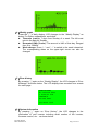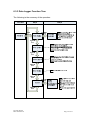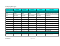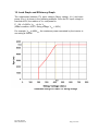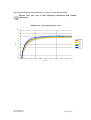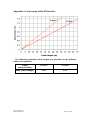
1
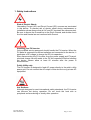
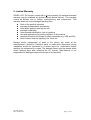
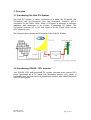
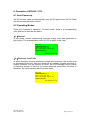
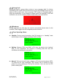
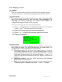
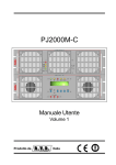
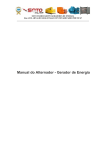
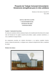
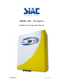
SOLEIL 10TL PV Inverter Installation and Operation Manual IV317E Rev.00 Date 2010-06-18 Pag. 1 of 57 Content READ THIS USER MANUAL BEFORE YOU START ....................... 4 1. SAFETY INSTRUCTIONS ............................................................. 5 2. LIMITED WARRANTY ................................................................... 7 3. OVERVIEW .................................................................................... 8 3.1 INTRODUCING THE GRID PV SYSTEM ............................................................................................. 8 3.2 INTRODUCING SOLEIL 10TL INVERTER ......................................................................................... 8 3.2.1 Dimensions of SOLEIL 10TL Inverter.................................................................................... 9 3.2.2 Identification .......................................................................................................................... 9 3.3 INTRODUCING GRAPHIC DATA LOGGER ........................................................................................ 11 3.3.1 Configuration ....................................................................................................................... 12 3.3.2 Features ............................................................................................................................... 12 3.3.3 Connection ........................................................................................................................... 12 3.3.4 Appearance .......................................................................................................................... 13 4. FEATURES .................................................................................. 14 5. INSTALLATION ............................................................................ 15 5.1 INSIDE THE PACKAGE .................................................................................................................... 15 5.2 MOUNTING YOUR SOLEIL 10TL .................................................................................................. 15 5.3 CONNECTING THE AC-OUTPUT CABLE ......................................................................................... 21 5.4 AC OUTPUT CONNECTOR SEAL .................................................................................................... 24 1. SCREW THE AC OUTPUT PLATE IN POSITION ON THE RIGHT SIDE AND USING TOWER SCREWS WITH HOLES ON THE LEFT SIDE. ................................................................................................................... 24 2. INSERT THE STEEL WIRE THROUGH BOTH HOLES OF THE TOWER SCREWS AND SEAL THE ENDS OF THE STEEL WIRE WITH THE SLEEVE. ........................................................................................................... 24 5.5 CONNECTING THE PV-PANEL ........................................................................................................ 24 5.6 CONNECTING TO THE LINE CIRCUIT BREAKER .............................................................................. 28 5.7 INSTALLATION CHECKLIST ............................................................................................................ 29 6. OPERATION OF SOLEIL 10TL ................................................... 30 6.1 AUTO POWER-UP .......................................................................................................................... 30 6.2 OPERATING MODES ...................................................................................................................... 30 6.3 USING THE LCD DISPLAY AND DATA LOGGER .............................................................................. 32 6.3.1 Operation ............................................................................................................................. 32 6.3.2 Display on LCD ................................................................................................................... 33 6.3.3 Data Logger Function Tree: ................................................................................................ 36 Note: Auto test function is required by DK5940. The test includes maximum and minimum AC voltage threshold, and maximum and minimum AC frequency threshold. If all of the above tests have been performed, the display shows the message TEST PASSED. ......................................... 42 7. COMMUNICATION INTERFACE ................................................. 43 7.1. RS-232 (ON INVERTER) ................................................................................................................ 43 7.2. COMMUNICATIONS SLOT FOR RS-485 MODBUS CONVERTER CARD ............................................ 43 7.3. USB (ON DATA LOGGER) ............................................................................................................. 43 8. DOWNLOADING DATA INSIDE DATA LOGGER ....................... 44 8.1. HOW TO EJECT / INJECT THE DATA LOGGER .................................................................................. 44 8.2. HOW TO ACCESS AND MANAGE LOG DATA .................................................................................. 45 9. TROUBLESHOOTING ................................................................. 49 IV317E Rev.00 Date 2010-06-18 Pag. 2 of 57 10. SPECIFICATIONS...................................................................... 52 11. COMPLIANCE OF STANDARDS .............................................. 53 12. LOAD GRAPH AND EFFICIENCY GRAPH .............................. 54 APPENDIX I: LINE LOSSES OF THE PV-INVERTER .................... 56 APPENDIX II: SELECTING THE LINE CIRCUIT BREAKERS ....... 57 IV317E Rev.00 Date 2010-06-18 Pag. 3 of 57 Read this User Manual before you start Congratulations on purchasing your SOLEIL 10TL Grid PV-Inverter (referred to in this manual as “PV-Inverter”, or simply the “device”). This PV-Inverter is a highly reliable product due to its innovative design and excellent quality control. The device is dedicated to high demand, 3 phase grid-linked PV systems. Additionally this product is IP65 rated for dusty or humid environments and is suitable for outdoor use. This manual contains important information regarding installation and safety operation of this unit. Be sure to read this manual carefully before using your PV-Inverter. If you encounter any difficulties during installation or operation, please refer to this manual before contacting your local dealer or representative. Thank you for choosing our product. Please keep this manual on hand for quick reference. Start enjoying SOLEIL 10TL and your life! IV317E Rev.00 Date 2010-06-18 Pag. 4 of 57 1. Safety Instructions Risk of Electric Shock: Alternating Current (AC) and Direct Current (DC) sources are terminated in this device. To prevent risk of electric shock during maintenance or installation please ensure that all AC and DC terminals are disconnected. Be sure to secure the Ground line to the Grid’s Ground, and double check the Line and Neutral are not confused with Ground. Handling your PV-Inverter: Only qualified service personnel should handle the PV-Inverter. When the PV-panel is exposed to sufficient radiation and connected to the device, it generates a DC voltage to charge the DC link capacitors. After disconnecting the PV-Inverter from the power supply and PV-panel, electrical charge can still reside in the DC link capacitors. Before handling the device, please allow at least 60 minutes after the power is disconnected. Public Utility only: The PV-Inverter is designed to feed AC power directly to the public utility power grid. Do not connect the AC-output of this device to any private AC equipment. Hot Surfaces: Although designed to meet international safety standards, the PV-Inverter can become hot during operation. Do not touch the heat sink or peripheral surfaces during or shortly after operation. IV317E Rev.00 Date 2010-06-18 Pag. 5 of 57 Maintaining and Servicing your PV-Inverter: Only authorized personnel are allowed to open the inverter for service purpose. CAUTION – Risk of electric shock from energy stored in capacitor, do not remove cover until 8 minutes after disconnecting all sources of supply. Unpacking and Installation: The SOLEIL 10TL PV-Inverter weighs 37 kg (81.5 lb). To avoid injury and for safety purpose, be sure to use proper lifting techniques and secure the help of someone to assist in the unpacking and installation of the inverter. IV317E Rev.00 Date 2010-06-18 Pag. 6 of 57 2. Limited Warranty SOLEIL 10TL PV-Inverter comes with a 5-year warranty. An optional extended warranty may be available by special request before delivery. This warranty covers all defects due to design, manufacturing and components. This warranty does not cover damages resulting from: Seal on the product is broken Improper transportation and delivery Unqualified persons opening the unit Improper installation Unauthorized modification, test or repairing Use and application beyond the definition in this manual Application beyond the scope of safety standards (e.g. VDE and DK) Acts of nature such as lightning, fire, storm etc. Repairs and/or replacement of parts or the device are made at the manufacturer’s discretion. Defective parts or malfunction discovered during installation should be presented in a written report for confirmation before applying for replacement or repair. The damage report must be issued within seven working days after receiving the PV Inverter. Manufacturer is not responsible for damages beyond the scope of this warranty. IV317E Rev.00 Date 2010-06-18 Pag. 7 of 57 3. Overview 3.1 Introducing the Grid PV System The Grid PV System is mainly composed of 4 parts: the PV-panels, the PV-Inverter, the AC-Connection Unit (the connection Interface) and a connection to the Public Utility. When a PV-panel is exposed to sufficient irradiation and connected to an inverter, it generates DC power. The PV-Inverter converts DC to AC and feeds in to the Public Utility via the AC-Connection unit. The following figure shows the PV-Inverter in the Grid PV System. 3.2 Introducing SOLEIL 10TL Inverter Your SOLEIL 10TL grid-connected PV inverter converts direct current (DC) power generated by a PV panel into alternating current (AC), which is compatible with the local electricity distribution network; also called the public utility, or grid system. IV317E Rev.00 Date 2010-06-18 Pag. 8 of 57 3.2.1 Dimensions of SOLEIL 10TL Inverter The dimension is in millimeters. 3.2.2 Identification On the left side of SOLEIL 10TL shows the type plate of the inverter. The type plate shows the Type, Specifications, and the Serial Number of the inverter. When encounter any difficulties during installation or operation, please record the Serial Number (SN) before contacting your local dealer or representative. IV317E Rev.00 Date 2010-06-18 Pag. 9 of 57 3.2.3 Specific Parts of SOLEIL 10TL Inverter The descriptions of the major parts of SOLEIL 10TL Inverter are indicated below: (1) 3 Pairs of DC-Input Terminals: Each input pair consists of positive and negative terminals. Refer to Installation Section for set-up information. (2) Cooling Fan: The inverter is equipped with 3 air cooling fans to eject heat dissipated by the heat sink. When the temperature of heat sink reaches 50ºC the fans automatically turn on. (3) RS232 Interface: Connect this port directly to your PC via an RS232 serial cable. (4) AC-Output Cable Gland: The cable gland is for securing the AC power wires L1 (Line 1), L2 (Line 2), L3 (Line 3), N (Neutral), Gnd (PE): 4/6mm2 (5) Ground (PE) Cable Gland: The cable gland is for securing the Ground (PE) wire for safety purpose. Refer to Installation Section for set-up information. G (Ground, PE): 10mm2 wires. (6) Communication Slot and Cover: The cover behind is a slot is to accommodate the RS485 MODBUS converter card. (7) Graphic Data Logger: This device displays and records useful information about the inverter operating status. IV317E Rev.00 Date 2010-06-18 Pag. 10 of 57 3.3 Introducing Graphic Data Logger To show the information of inverter, there is a graphic Data Logger in the unit. This Data Logger can show various information of the inverter such as operational status and warning message. In addition, it can be removed from its slot to a place user prefers. A standard 1.8-meter cord is attached with the Data Logger. If the user wishes to extend the length, a standard RS232 (DB9) cable of maximum 15 meters in length can be use for communication purpose.* * This only applies to inverter with removable data logger. IV317E Rev.00 Date 2010-06-18 Pag. 11 of 57 3.3.1 Configuration The following table indicates the main specification of the Data Logger: LCD Displayed Information Storage Period Storage Media Data Download Monochrome Each I/P power, O/P power, Operation mode and warning message 3 years SD card Via mini USB 3.3.2 Features Removable Data Logger * The Data Logger is removable from its inverter. The display is a module designed so that users can remove and put back the module easily. Between the display module and inverter, there is a standard DB9 RS232 cable at length of 1.8m in-between. The display can be mounted on wall after taking out from its slot at inverter. Multicolored back light The backlight of the LCD changes according to its status. There are 3 colors and their indications are: Green: Start-up and normal status Red: Fault Status. In this status, inverter disconnected from grid due to system fault or inverter failure. These faults and failures are defined in “error message table” later on. Yellow: Warning Status. Inverter disconnected from grid due to system fault for the past 48 hours, but inverter reconnected again. Data download You can download and access logger data with a PC via mini USB cable and manage internal data. For detail information, please refer to 8. Downloading Data inside Data Logger. 3.3.3 Connection The Data Logger can be either located on the inverter or remotely mounted on a wall. A 1.8-meter cord connects the display module and the main inverter unit.* * This only applies to inverter with removable data logger IV317E Rev.00 Date 2010-06-18 Pag. 12 of 57 3.3.4 Appearance LCD: 128 x 64 graphic, monochrome Navigation Pad: “↑”, “↓”, “→” , “←” and “OK” in the center. Back light: 3 colors Pac:0W TEMPERATURE:42.8 Iac:0.0/0.0/0.0A Vac:219.4/219.3/219.3V STATUS:Normal Pac:0W TEMPERATURE:42.8 Iac:0.0/0.0/0.0A Vac:0.0/0.0/0.0V STATUS:Fault No Utility Pac:0W TEMPERATURE:42.8 Iac:0.0/0.0/0.0A Vac:219.4/219.3/219.3V STATUS:Normal 02/12/09 15:57 02/12/09 15:58 IV317E Rev.00 Date 2010-06-18 02/12/09 15:59 Pag. 13 of 57 4. Features Transformerless design Euro efficiency ≧ 95% at nominal DC input Islanding detection methods: passive and active MPPT efficiency >99% Firmware update capability GFCI embedded Lead-free, RoHS complied 3 MPP trackers Graphic data logger IV317E Rev.00 Date 2010-06-18 Pag. 14 of 57 5. Installation 5.1 Inside the Package The following items are included in the SOLEIL 10TL Package: (1) PV-Inverter x 1 (2) Installation and Operation Manual x 1 (3) Mounting Screws x 4 and Snap Bushings x 4 (4) Safety-lock screws x 2 (5) Mounting Bracket for the inverter x 1 (6) Service Card x 1 (7) Mounting plate of the data logger x 1 (8) Screws for mounting the data logger x 2 (9) AC Output Cover x 1 (10) Rubber Bushing for AC connection (2 types) (11) DC connector (3 pairs) 5.2 Mounting your SOLEIL 10TL Suggestions before mounting To obtain optimal results from your PV-Inverter, please consider the following guidelines before installing the device: Do not expose the PV-Inverter to direct sunlight. Direct sunlight increases the internal temperature that may reduce conversion efficiency. Check the ambient temperature of installation is within specified range -20 ~ +55C. Check the altitude of installation is less than 2000m. The AC grid voltage is 400Vx3, -15% +10%, 50Hz. Electric utility company has approved the grid connection. Qualified personnel are performing the installation. Adequate convection space surrounds the inverter. Inverter is being installed away from explosive vapors. No flammable items are to be near the inverter. No mounting on wooden flammable surface. SOLEIL 10TL can be installed and operated at locations where the ambient temperature is up to 55C. However, for optimal operation, it is recommended that SOLEIL 10TL is installed where the ambient temperature is between 0~40C. IV317E Rev.00 Date 2010-06-18 Pag. 15 of 57 To mount the inverter to a wall, please follow the steps: (1)It is recommended to choose a dry place, out of direct sunlight with ambient temperature between 0 and 40°C (2)Select a wall or solid vertical surface which is strong enough to support the inverter. (3)The PV-Inverter requires adequate cooling space for heat dissipation. Reserve at least 20cm above and 20cm (measured start from the bottom of the AC cover) below the inverter. Each inverter should have minimum of 20cm space to each other for multiple inverters installation. IV317E Rev.00 Date 2010-06-18 Pag. 16 of 57 (4) Fix the Bracket by using Outer Mounting Holes: (a) To install the device to a wall, mark 4 outer holes at the back of the bracket as illustrated below. (b) Drill the 4 marked holes in the wall, and then drive in the 4 Snap Bushings. Now insert the screws, and tighten. (c) Mount the PV-Inverter onto the base plate as illustrated below. IV317E Rev.00 Date 2010-06-18 Pag. 17 of 57 (5) Fix the Bracket by Using Central Mounting Holes: (a) To install the device to a narrow upright, mark 3 central holes at the back of the bracket as illustrated below. (b) Drill the 3 marked holes in the wall, and then drive in the 3 Snap Bushings. Now insert the screws, and tighten. (c) Mount the PV-Inverter onto the base plate as illustrated below. IV317E Rev.00 Date 2010-06-18 Pag. 18 of 57 (6) Mount the PV-Inverter onto the bracket as illustrated: (7) Insert the Safety Lock screws to fix the PV-Inverter in place. (8) Ensure the device is properly fixed to the bracket. IV317E Rev.00 Date 2010-06-18 Pag. 19 of 57 (9)Users can install Data Logger separately from the main unit. The mounting plate of the data logger and 2 screws are included in the accessories package: * (a) Fix the mounting plate of the data logger by 2 screws. (b) Drill 2 holes in the wall, insert the screws, and tighten to fix the Data Logger in place. * This section applies only to inverter with removable data logger. IV317E Rev.00 Date 2010-06-18 Pag. 20 of 57 5.3 Connecting the AC-Output Cable Connect your PV-Inverter to the AC-Junction box via the AC-output cable and Ground cable as shown in the following steps: (1) Find the recommended AC-output cable size: Do not use cables where losses will exceed 1%, see Appendix 1 L1 (Line 1), L2 (Line 2), L3 (Line 3), N (Neutral), Gnd (PE): 4/6mm2 cross-sectional area wire Gnd (PE): 10mm2 cross-sectional area wire (2) Remove the rubber plug from inside the AC and Ground connector socket. (3) Insert AC cables to the left side of the connection lock, rubber bushing in the accessory package, and AC-output cover. Then, insert Ground cable to the right side of the connection lock, rubber bushing, and AC-output cover. (4) The choice of cable together with the way it is routed, the ambient temperatures the inverter operates at, and other underlying conditions determines the maximum AC fuse protection used for the inverter. See Appendix 2 IV317E Rev.00 Date 2010-06-18 Pag. 21 of 57 (5) Insert the AC-output cables; Brown wire to L1, the Black wire to L2, the Grey wire to L3, the Blue wire to N (Neutral), and the Yellow-Green wire to Gnd (PE) of the terminal block. (6) Fix the L1, L2, L3, N, and Gnd (PE). Please note that all 5 wires should be firmly connected. (7) Fix the other 10mm2 Gnd (PE) wire firmly. IV317E Rev.00 Date 2010-06-18 Pag. 22 of 57 (8) Fix the AC output cover back with a screwdriver. (9) Twist on the connector cable gland to lock the bushing and cable. IV317E Rev.00 Date 2010-06-18 Pag. 23 of 57 5.4 AC Output Connector Seal (only for DK5940 models) 1. Screw the AC output plate in position on the right side and using tower screws with holes on the left side. 2. Insert the steel wire through both holes of the tower screws and seal the ends of the steel wire with the sleeve. 5.5 Connecting the PV-Panel For connecting the DC input, the connected strings must consist of modules of the same type. The number, orientation, and tilt of the panels may differ for different application usage. The following are the specification of the plug connectors. Connector Type Female panel receptacle Cable connection dimension Max. Rated Current Ø 3mm connecting system 20A Ø 3mm connecting system 20A Male panel receptacle Suggestions before connecting the PV Panel To obtain optimal results from your PV-Inverter, please consider the following guidelines before connecting the PV Panel to the device: (1)First make sure the maximum open circuit voltage (Voc) of each PV string is below 800VDC under any condition. IV317E Rev.00 Date 2010-06-18 Pag. 24 of 57 (2)Always connect PV-Panel positive (+) terminal to PV-Inverter DC positive (+) terminal, and PV-Panel negative (-) terminal to PV-Inverter DC negative (-) terminal. (3)Each set of PV-Inverter DC terminal converts maximum DC input current of 13A. As a result, 3 pairs of PV-Inverter DC terminals can take a combined input current of up to 39A. (4)Methods to detach MC4 connector: Two ways of using the same tool to detach the MC4 connector can be seen in Fig. 1 and Fig. 2: Fig. 1 Fig. 2 IV317E Rev.00 Date 2010-06-18 Pag. 25 of 57 The following diagrams show the PV system with/without SOLEIL 10TL DC Switch (DCW 10-3-3). Illustration of the PV System with SOLEIL 10TL DC Switch (DCW 10-3-3): IV317E Rev.00 Date 2010-06-18 Pag. 26 of 57 Illustration of the PV System without SOLEIL 10TL DC-Switch: Caution: If you wish to disconnect the DC input cable from the inverter for maintenance or other purpose, please make sure you disconnect the cable on the AC terminal side first. Failure to do so might cause the PV panels to damage due to reverse current or sudden over voltage. IV317E Rev.00 Date 2010-06-18 Pag. 27 of 57 5.6 Connecting to the Line Circuit Breaker The AC line circuit breaker is an interface between your PV-Inverter and the Public Utility. It may consist of an electrical breaker, fuse and terminals for connection to both the PV-Inverter and the Public Utility. This AC line circuit breaker must be designed by a qualified technician to comply with local safety standards. IV317E Rev.00 Date 2010-06-18 Pag. 28 of 57 5.7 Installation Checklist (1) High voltages exist when the PV-Panel is exposed to the Sun. Exposed terminals of the PV-Panel are under tension, and can cause electric shock. Avoid making physical contact with those parts of the device. (2) After the PV-Panels are connected to the PV-Inverter, the output voltage is greater than 300VDC and when the AC grid is not connected to the inverter, the Data Logger LCD displays the following: Pac:0W TEMPERATURE:42.8 Iac:0.0/0.0/0.0A Vac:0.0/0.0/0.0V STATUS:Fault No Utility / / (3) Check the connection between your PV-Inverter and the AC Connection System, and then check the connection between the Public Utility and the AC junction box. Close the AC breaker or fuse in the unit. (4) Under normal operation, the Data Logger LCD shows the following as an example: Pac:0W TEMPERATURE:42.8 Iac:0.0/0.0/0.0A Vac:219.4/219.3/219.3V STATUS:Normal 02/12/09 15:59 (5) When the display is green, the inverter is feeding power to the grid. Under such condition, you have installed the inverter successfully. Before connecting PV-Panels to DC terminals, make sure the polarity of each connection is correct. An incorrect connection could permanently damage the device. IV317E Rev.00 Date 2010-06-18 Pag. 29 of 57 6. Operation of SOLEIL 10TL 6.1 Auto Power-up The PV-Inverter starts up automatically once the DC-power from the PV Panel is sufficient and the fuse is closed. 6.2 Operating Modes There are 4 modes of operation. For each mode, there is a corresponding color and text to indicate the status. (1)Normal In this mode, inverter continuously converts energy from solar generator to grid (utility). The corresponding color of LCD is green in this case. Pac:0W TEMPERATURE:42.8 Iac:0.0/0.0/0.0A Vac:219.4/219.3/219.3V STATUS:Normal 02/12/09 15:59 (2)Recovery from Fault In some situations such as abnormal voltage and frequency, the inverter has to disconnect from grid. After the situations are cleared, inverter recovers to normal condition. For the coming 48 hours, the LCD backlight will be yellow as following picture. If there is no further abnormal event after 48 hours of operation, the color switches back to green again. Pac:0W TEMPERATURE:42.8 Iac:0.0/0.0/0.0A Vac:219.4/219.3/219.3V STATUS:Normal 02/12/09 15:59 IV317E Rev.00 Date 2010-06-18 Pag. 30 of 57 (3)During Fault During grid fault or system failure (refer to “error message table” for further information) the inverter disconnects from the grid, the backlight turns red, and alarm is ON to notify user. User can press “OK” button on navigation pad to clear fault notification. In this condition, please check the message. If the fault notification can not be cleared, please contact with your local service. (4)Shutdown During night and very dark day, the inverter automatically shuts down. In this condition, Data Logger and the navigation pad are inactive. (5)Three Operating States: Standby: During normal operation, the PV-Inverter is in “standby” state and the open circuit voltage is between 200V to 300V. Pac:0W TEMPERATURE:42.8 Iac:0.0/0.0/0.0A Vac:219.4/219.3/219.3V STATUS:STANDBY 02/12/09 15:59 Waiting: Between 300V and 350V in DC side, the device is in “waiting” state, in the meanwhile, the inverter is checking both DC And AC conditions and waiting for connection. Pac:0W TEMPERATURE:42.8 Iac:0.0/0.0/0.0A Vac:219.4/219.3/219.3V STATUS:Waiting 02/12/09 15:59 Normal: To be in “normal” state, voltage on DC side must be above 350V. To check the DC wire connection, this inverter tries to disturb its input power for every starting-up. During the process, user can see the DC power reading drift. Pac:0W TEMPERATURE:42.8 Iac:0.0/0.0/0.0A Vac:219.4/219.3/219.3V STATUS:Normal 02/12/09 15:59 IV317E Rev.00 Date 2010-06-18 Pag. 31 of 57 6.3 Using the LCD Display and Data Logger 6.3.1 Operation (1)Keys on the data logger: On the data logger, there are 5 keys used to change and operate. Generally, the functions of keys are defined as followings. “→”: View the lower layer (1st to 2nd) or move the cursor right “←” : View upper layer (2nd to 1st) or move the cursor left “↑” : View the previous screen or move the cursor up “↓” : View the next screen or move the cursor down “OK”: Set or confirm (2)Back light of LCD As described in previous section, the color of backlight changes according to operation status. To save power, the light remains illuminated only for 3 minutes after last operation. However, in case a failure or error occurs, other than the backlight goes red, the backlight flashes every second until user presses the key according to instruction on the LCD. (3)Audio Alarm To inform the user, data logger will emit audio alarm in cases of following: (a)Inverter failure (b)Memory capacity of data logger is less than 5% (c)Convection fan is not able to rotate for any reason This alarm also can be turned “off” by setting in the “System Display”. To do this, please refer to “System Display” section afterwards. (4)Behavior in case memory is full Once the capacity of memory is less than 5%, data logger will emit audible alarm. At that moment, user should manage the data inside and try to clear the memory by using a PC. In case user ignores the warning and does not clear the memory, after memory is 100% full, the latest data will overwrite the earlier ones. IV317E Rev.00 Date 2010-06-18 Pag. 32 of 57 6.3.2 Display on LCD (1)Startup After the inverter starts up, the LCD shows logo and firmware version. The frame lasts for 3 seconds and changes to text information below. (2)Text display The display shows four measurements and one status. The bottom-right part of the display shows the time and date. On occurrence of a “warning” or “error” message, the bottom line “Status” is automatically replaced by the error message. The user can change the four monitoring parameters. (a)Press “→” to high-light the monitoring parameter at the first line. By using “↑” and “↓”, the user can shift to the next line. (b)Press “OK” to begin setting the monitoring parameter. (c)Press “↑” or “↓” to select the monitoring parameter of the line. (d)Press “OK” to confirm. Pac:3308W TEMPERATURE:37.0 Iac:5.1/5.1/5.2A Vac:220.5/217.3/218.6V STATUS:Normal 02/12/09 15:59 (3)Daily graph By pressing the “↓” key in text display, screen on LCD is transformed to daily graph as below. The graph indicates the AC power trend of a specified date. Further explanations are stated below: Time-axis (x-axis): On the frame, the longest period is 12 hours. The number represents the hour. The first recorded data of a day is plotted on the left most point. In case the recorded data of a day is longer than 12 hours, press “OK” first and then press “→” and “←” to move the graph to time interested. Press “OK” again to terminate the moving. Power-axis (y-axis): From 0 to 13KW. Each point is the averaged power during 6-minute interval. Date: On the upper right corner, the date of present display is shown. To see daily graph of expected day, press “→“ and “←” to select IV317E Rev.00 Date 2010-06-18 Pag. 33 of 57 (4)Weekly graph Press the “↓” of daily display, LCD changes to the “Weekly Display” as below. For further explanations, see below: Time-axis (x-axis): 7 days from Sunday of a week. The left most point is the data for Sunday. Generated KWh (Y-axis): The amount in kWh of that day. Ranged from 0 to 130kWh. Week change: Press “←“ and “→” to switch to the week interested. The corresponding dates on the upper-right corner can also be changed. (5)Error history By pressing “↓” again on the “Weekly Display”, the LCD changes to “Error Message” as shown below. The LCD displays two recorded error events for each page. ERROR HISTORY E1:Isolation fault @ 02/12/09 2:44 VALUE=N/A E2:Grid fault @01/12/09 10:21 (6)System Information By pressing “↓” again on “Error History”, the LCD changes to the information of your inverter including serial number of the inverter, firmware version, etc… as shown below. IV317E Rev.00 Date 2010-06-18 Pag. 34 of 57 SYSTEM INFORMATION S/N: ST20090623 Version: O0.11-00.07 MEMORY: 0.1% DATE: 02/12/09 WED TIME: 02:52:32 GMT+01 AUDIO ALARM: ON LANGUAGE: ENG The following are the monitoring parameters shown in “System Display”: SN: The serial number of the inverter Version: The firmware version of the inverter Memory: The memory status of the Data Logger Date: The date setting of the inverter Time: The time setting of the inverter Audio Alarm: “On” or “Off”, the status of the setting Language: The language setting of display To change the Date, Time, Audio and Language settings: (a)Press “→” and then press“↑” or “↓” to change the parameter to the desired setting. (b)Press “OK” to confirm. Use “↑” and “↓” to alter the value (c) Press “OK” to confirm. IV317E Rev.00 Date 2010-06-18 Pag. 35 of 57 6.3.3 Data Logger Function Tree: The following is the summary of the operation: IV317E Rev.00 Date 2010-06-18 Pag. 36 of 57 6.4 Display Messages Operating conditions In English In German In Spanish In Italian Description Normal Working Status Power off No display No display No display No display In case of input voltage < 200V, PV inverter is totally shutdown Standby Status: Standby Status: Standby ESTADO: ENCENDIDO Stato: Standby Input voltage range: 200V ~ 260V Initialization & waiting Status: Waiting Status: Warten ESTADO: PREPARADO Stato: In attesa Input voltage range: 260 ~ 350V Check grid Status: Checking xxxs Status: Netz-Prüf xxxs ESTADO: TEST xxxs Stato: Ricerca MPP xxxs In case of PV voltage > 350V, inverter is checking feeding conditions Feeding grid, MPPT Status: Normal Status: Normalbetriebe ESTADO: CONECTADO RED Stato: Conneso Normale Inverter is feeding power. After 10 seconds of this display, LCD will show wattage. Waiting for reconnect to grid Status: Reconnect xxxs Status: Kontakt xxxs ESTADO: RECONEX xxxs Stato: Connes.Retexxxs The time for reconnect to grid FLASH Status: FLASH Status: FLASH ESTADO: FLASH Stato: Aggiornamento FLASH firmware SLAVE FLASH Status: SLAVE FLASH Status: SLAVE FLASH ESTADO: FLASH SEC Stato: Aggiorn. Slave SLAVE FLASH firmware FAULT Status: Fault Status: Fehler ESTADO: FALLO Stato: errore See “System Fault”, “Inverter Fault” to know the fault detail Pdc: xxxx/xxxx/xxxxW Pdc: xxxx/xxxx/xxxxW Pdc: xxxx/xxxx/xxxxW The individual DC input power Monitoring Parameters Instantaneous Input power IV317E Rev.00 Date 2010-06-18 Pdc: xxxx/xxxx/xxxxW Pag. 37 of 57 Operating conditions In English In German In Spanish In Italian Description Instantaneous Output power Pac: xxxxxW Pac: xxxxxW Pac: xxxxxW P.Istant.: xxxxxW The real time output power in xxxx W Accumulated energy information Etot: xxxxxxxxx.xkWh E-tot: xxxxxxxxx.xkWh Etot: xxxxxxxxx.xkWh Etot: xxxxxxxxx.xkWh Total energy to has been fed to grid since inverter was installed 3-phase Grid voltage Vac: xxx.x/xxx.x/xxx.xV Uac: xxx.x/xxx.x/xxx.xV Vac: xxx.x/xxx.x/xxx.xV VAC: xxx.x/xxx.x/xxx.xV Grid voltage in xxx.x VAC for 3 phases Grid frequency Frequency: xx.xHz Frequency: xx.x Hz Fac: xx.x Hz Frequenza: xx.x Hz Grid frequency in xx.x Hz Feeding current Iac: xx.x/xx.x/xx.xA Iac: xx.x/xx.x/xx.xA Iac: xx.x/xx.x/xx.xA IAC: xx.x/xx.x/xx.xA Feeding current amount in xx.x A PV array voltage Vdc: xxx/xxx/xxxV Udc: xxx/xxx/xxxV Vdc: xxx/xxx/xxxV VDC: xxx/xxx/xxxV Input voltage of PV array, xxx VDC PV array current Idc: xx.x/xx.x/xx.xA Idc: xx.x/xx.x/xx.xA Idc: xx.x/xx.x/xx.xA IDC: xx.x/xx.x/xx.xA Input DC current of tracker n Daily Energy Etoday: xxx.xkWh E-Heute: xxx.xkWh Ehoy: xxx.xkWh Oggi: xxx.xkWh The accumulated kWh of that day Working Hour H-total: xxxxxxhr h-Gesamt: xxxxxxhr Hfun: xxxxxx Ore tot. Funz.: xxxxxx Total working hours of inverter Internal Temperature Temperature: xx.xºC Temperatur: xx.xºC TEMPERATURA: xx.xºC Tempo.Interna: xx.x°C Temperature is indicated in Celsius Isolation failure Isolation Fault Isolationsfehler ERR AISLAMIENTO Err.Isolameto Earth fault of the PV-panels or failure of surge voltage protection GFCI active Ground I Fault Fehlerstrom ERR DERIVACION Disp.terra alta Leakage current on ground conductor is too high System Fault IV317E Rev.00 Date 2010-06-18 Pag. 38 of 57 Operating conditions In English In German In Spanish In Italian Description Grid failure Grid Fault Netzfehler ERR RED Dati rete insuf. Grid measured data is beyond the specification (voltage & frequency) Relay failure Relay Failure Relaisfehler ERR CONTACTOR AC Err.impedenza The output relay is out of order No utility No Utility Kein Netz SIN RED No rete Utility is not available Input voltage too high PV over voltage DC-Überspg SOBRETENSION DC SovravoltaggioPV Input voltage higher than 800V Consistent failure Consistent fault Konsistenzfehler ERR MICROS Err.processore The readings of 2 microprocessors are not consistent. It could be caused by CPU and/or other circuit do not function well. Temperature too high Over temperature Übertemperatur SOBRETEMPERATURA Temp.in eccesso The internal temperature is higher than normal value Output DC injection too high DC INJ High DC INJ zu hoch NIVEL DC ALTO Uscita DC alta Output DC injection is too high EEPROM problem EEPROM failure EEPROM Fehler ERR EEPROM Err EEPROM Reading/writing of EEPROM failed Communication failure between microprocessors Sci Failure CPU Fehlfunktion ERR COM Err.accesso dati The communication between MCU inside is abnormal DC bus voltage is too high High DC Bus U/dc bus zu hoch NIVEL BUS ALTO DC Bus alto The DC BUS inside is higher than expected DC bus voltage is too low Low DC Bus U/dcbus zu klein NIVEL BUS BAJO DC Bus basso The DC BUS inside is lower than expected Output DC sensor abnormal DC Sensor Fault DC Sensor Fehler ERR SENSOR DC Err.Sensore DC The output DC sensor is abnormal Inverter Fault IV317E Rev.00 Date 2010-06-18 Pag. 39 of 57 Operating conditions In English In German In Spanish In Italian Description GFCI detection problem GFCI Failure FI-Fehler ERR DIFERENCIAL Err.Sens.Terra The GFCI circuit is abnormal Master and Slave firmware mismatch M-S Ver. Fault M-S Ver. Fault ERR VER MICRO FW incompatibile Firmware mismatch between Master and Slave Memory card full Memory Full Memory Full MEMORIA LLENA Memoria piena There is not enough space to store data Serial Number SN: xxxxxxxxxxxxxxxx SN: xxxxxxxxxxxxxxxx S/N: xxxxxxxxxxxxxxxx Seriale: xxxxxxxxxxxxxxxx 16 characters, unique serial number Firmware version Version: xx.xx-xx.xx Version: xx.xx-xx.xx FIRMWARE: xx.xx-xx.xx Ver.FW: xx.xx-xx.xx The Master and Slave CPU F/W version information SD card memory Memory: xx.x% Speicher: xx.x% MEMORIA: xx.x% Utilizzo mem: xx.x% Memory utilization percentage on SD card Date display Date: DD/MM/YY Sun Datum: DD/MM/YY Son. FECHA:DD/MM/YY DOM DATA:DD/MM/YY Dom. Date display Date display Date: DD/MM/YY Mon Datum:DD/MM/YY Mon. FECHA:DD/MM/YY LUN DATA:DD/MM/YY Lun. Date display Date display Date: DD/MM/YY Tue Datum:DD/MM/YY Die. FECHA:DD/MM/YY MAR DATA:DD/MM/YY Mar. Date display Date display Date: DD/MM/YY Wed Datum:DD/MM/YY Mit. FECHA:DD/MM/YY MIE DATA:DD/MM/YY Mer. Date display Date display Date: DD/MM/YY Thu Datum:DD/MM/YY Don. FECHA:DD/MM/YY JUE DATA:DD/MM/YY Gio. Date display Date display Date: DD/MM/YY Fri Datum:DD/MM/YY Frei. DATA:DD/MM/YY Ven. Date display System Information IV317E Rev.00 Date 2010-06-18 FECHA:DD/MM/YY VIE Pag. 40 of 57 Operating conditions In English Date display Date: DD/MM/YY Sat Time display In German In Spanish Datum:DD/MM/YY Sam. FECHA: DD/MM/YY SAB In Italian Description DATA: DD/MM/YY Sab. Date display Time: HH/MM/SS GMT+xx Zeit:HH/MM/SS GMT+xx HORA: HH/MM/SS GMT+xx Ora: HH/MM/SS GMT+xx Time display Audible alarm setting on Audible Alarm: On Alarm: An ALARMA SONORA: ON Allarme: attivo Set up audible alarm Audible alarm setting off Audible Alarm: Off Alarm: Aus ALARMA SONORA: OFF Allarme: disattivato Set up audible alarm Setting Language Language: English Sprache: Englisch IDIOMA: ENG Lingua: ENG Set up of the display language Setting Language Language: ESP Sprache: ESP IDIOMA: ESP Lingua: Spagnolo Set up of the display language Setting Language Language: German Sprache: Deutsch IDIOMA: GER Lingua: Tedesco Set up of the display language Setting Language Language: ITA Sprache: ITA IDIOMA: ITA Lingua: Italiano Set up of the display language Memory is to be full Memory left xx.x% memory left xx.x% MEMORIA LIBRE xx.x% Memoria rimasta xx.x% When the memory space of card is less than 5%, this warning should be displayed in the status. Fan Lock Fan Lock FanLock ERR VENTILADOR BloccoVentil. The fan for heat dissipation is stopped abnormally Ver xx.xx Ver xx.xx Ver xx.xx Ver xx.xx LCD Firmware version Warning Message Other Message Initial screen IV317E Rev.00 Date 2010-06-18 Pag. 41 of 57 Operating conditions In English USB connection USB CONNECT Daily graph No Daily Records Daily graph In German USB angeschlossen In Spanish In Italian Description CONEXION USB USB Connessa Connect to PC with USB Keine Tagesaufz. NO HAY DATOS Giorno: Nessun dato No data for daily graph display Please Wait Bitte warten ESPERE POR FAVOR Attendere prego data processing Weekly graph No Weekly Records Keine Wochenaufz. NO HAY DATOS Settim: Nessun Dato No data for weekly graph display Error history Error History Fehlergeschichte NO HAY DATOS Archivio errori banner Error history No Error History Keine Fehlergeschi. NO HAY DATOS Nessun Dato No data for error history display Error history Value= N/A Value= N/A VALOR= SIN VALOR Valore= N/D fault value is not available Error history Value= xxxx xxxx xxxx Value= xxxx xxxx xxxx VALOR= xxxx xxxx xxxx Valore= xxxx xxxx xxxx display fault value System display SYSTEM INFORMATION Systemanzeige INFORMACION SISTEMA Informazioni sistema banner Display after error Press OK to Clear Presse OK zum Löschen PULSE OK PARA BORRAR tasto OK per tomare Press OK to clear fault message box Auto Test* PRESS OK TO START PRESS OK TO START tasto OK per tomare Press OK to start Auto Test PRESS OK TO START Note: Auto test function is required by DK5940. The test includes maximum and minimum AC voltage threshold, and maximum and minimum AC frequency threshold. If all of the above tests have been performed, the display shows the message TEST PASSED. IV317E Rev.00 Date 2010-06-18 Pag. 42 of 57 7. Communication Interface 7.1. RS-232 (on inverter) Your PV-Inverter is equipped with a versatile communications interface. Use SOLEIL 10TL “Pro Control” to monitor the status of multiple inverters. Firmware upgrades are also available via this interface. SOLEIL 10TL is integrated with a DB9 socket for the RS-232 interface. Open the DB9 socket cover before use. Pin assignment of this DB9 socket is stated as below: 7.2. Communications slot for RS-485 ModBus Converter Card Your PV-Inverter has an extended slot for the communication interface. A SOLEIL 10TL RS-485 ModBus card is fitted to extend the communication functions of the inverter. To use this slot, please use a screwdriver to open the cover, insert the card into the slot and wire through the rubber bushing. For further information, refer to manual of related interface card. 7.3. USB (on Data Logger) The Data Logger comes with a mini USB connector for your PC USB host interface. Open the mini USB socket cover before use. IV317E Rev.00 Date 2010-06-18 Pag. 43 of 57 8. Downloading Data inside Data Logger To manage the data inside the Data Logger, please take out the Data Logger from inverter and access its internal data via USB cable. The Data Logger is powered directly by the PC’s USB port. * 8.1. How to eject / inject the Data Logger (1)Unscrew the LCD panel and then take the data logger out of the chassis. (2)After taking out, you can see a cable between Data Logger and inverter, unbind the cable if necessary. The cable can be extended to 1.8m at most. To get further extension, you can use a standard RS-232 cable to do that. To separate the Data Logger from inverter, disconnect RS-232 connector on it. (3)When you want to place back the Data Logger, please use the tie provided to bind the cable as shown above. Then, cram the cable and slide the Data Logger into the inverter, slightly push the Data Logger on the side, the Data Logger will be locked. * This section only applies to inverter with removable data logger. IV317E Rev.00 Date 2010-06-18 Pag. 44 of 57 8.2. How to Access and Manage Log Data (1) Remove the Data Logger from the inverter and disconnect the RS-232 cable. Unscrew and take off the cover of mini-B USB port.** For PC with Windows ME, 2000, and XP, it is not necessary to install driver to access the data logger. For PC with Windows 98, to access the data logger, driver for the data logger is needed. **Do not remove the data Logger while the inverter unit is working.** (2)Connect the mini USB to Data Logger and Type A USB to PC. LED will show “USB CONNECT” when Data Logger is connected to PC properly. (3)Click “My Computer” – “Removable Disk” in your PC. * This section applies to inverter with removable data logger. For inverters with embedded data logger, you can find the mini USB connector at the side of the inverter for accessing the data. IV317E Rev.00 Date 2010-06-18 Pag. 45 of 57 (4)Copy the “DAILY” folder in the “Removable Disk” and paste it on the “Desktop.” (5)Execute Pro-Control program. Then, click “File”, select “Export/Import”. Please contact your local dealer or representative for the installation for this program. (6)Select “Date from” and “Date to” the period which you prefer. Then, click “Import” button. IV317E Rev.00 Date 2010-06-18 Pag. 46 of 57 (7)Select “DAILY.dat” file under your previous saved DAILY folder. Then, click “Open” button. (8)Click “View” button and the log data will be processed by Pro-Control software in few seconds. (9)Click “Export” button IV317E Rev.00 Date 2010-06-18 Pag. 47 of 57 (10)Click “Save” button. Then, log data will be saved in .CSV format in your preferred directory in your PC (11) Click “OK” button. (12)Double click “DAILY.CSV” file in your preferred directory in your PC. After that, you can manipulate the log data with Microsoft Excel. IV317E Rev.00 Date 2010-06-18 Pag. 48 of 57 9. Troubleshooting Your PV-Inverter requires very little maintenance. When unexpected situation occurs, please refer to the following table for quick troubleshooting before contacting your local service. The following table lists common fault messages and ways to cope with the fault or error. Fault Analysis and Actions Fault Message Fault definition The ground 1. current detected by inverter is higher than threshold 2. Ground I Fault 3. 4. Grid measured 1. data is beyond the specification (voltage & frequency) 2. 3. System Fault 4. 5. 6. Grid Fault 7. Inverter is not able to detect AC voltage 1. 2. 3. No Utility 4. 5. IV317E Rev.00 Date 2010-06-18 Proposed Actions for End-user Obstacle, humidity 1. Disconnect AC 1. or water exits connection of inverter between AC LINE by opening AC and/or NEUTRAL to switch. 2. earth ground 2. Check the AC Obstacle, humidity junction box and 3. or water exits wiring of system. between AC LINE Clear obstacle ONLY 4. and/or NEUTRAL to IN SAFE earth ground in the CONDITIONS junction box 3. Reconnect AC 5. The Insulation of connection, check the AC wires is broken status of inverter that could be bit by 4. If the problem rat or any animals persists, call local Inverter is abnormal service The detected AC 1. If this problem 1. voltage is occurs seldom (such beyond/under the as 1 time a day), no setting of inverter action is necessary 2. The detected AC 2. If the problem occurs frequency is frequently, do the beyond/under the actions below 3. setting of inverter 3. Find the device with AC connection is high power not correct consumption near 4. Grid condition is your AC system weak or unstable 4. Use inverter Other high-power software to check 5. consumption device the setting of is affecting the grid inverter. The setting system should be in the The setting of range listed in inverter is deviated specification 6. from its default 5. If the settings are not values correct, call your Inverter is abnormal service for changing 6. Use inverter software or monitoring device to collect data. Send the data to professionals for further investigation 7. Consult your utility power supplier, understand the grid conditions 8. Ask help of your installer Grid is not available 1. Make sure the 1. AC connection is breaker and switch incorrect on AC side are close AC switch between 2. Check the AC wiring 2. 3. inverter and utility 3. If the problem continues, call your is not ON AC fuse and/or local service breaker is open Inverter is abnormal Possible Causes Proposed Actions for Professionals Disconnect AC side of inverter by opening AC switch Disconnect the DC side from the inverter Check both the AC and DC wiring and insulation Reconnect AC connection, check the status of inverter If the problem persists, please Update the firmware according to instructions, or Replace the inverter Check the system connection including polarities and security first Find the devices with high power consumption near the AC system Consult the utility power supplier, understand the grid conditions Use inverter software to monitor the frequency and voltage If the measured data beyond the setting, under the permission of utility supplier, use the software to change parameters If the situation is not improved after changing parameters, please Update the firmware according to instructions, or Replace the inverter Make sure the breaker and switch on AC side are close Check the AC wiring If the problem continues, replace the inverter Pag. 49 of 57 Fault Message PV over Voltage Consistent Fault Over Temperature Inverter Failure Relay Failure DC INJ High EEPROM Failure SCI Failure High DC Bus IV317E Rev.00 Date 2010-06-18 Proposed Actions for Proposed Actions for End-user Professionals The detected 1. Open DC connection 1. Check the open PV 1. The PV array PV voltage is voltage is too high of inverter and voltage, and see if it is higher than 2. Inverter is abnormal reconnect more than or too close to specification 2. If the fault continues, specification call your local 2. If PV voltage is much less service than specification and the problem still occurs, please replace the inverter The readings of 1. Software problem 1. Open all DC 1. Open all DC connections 2 2. Circuits inside connections of of inverter microprocessors inverter are inverter 2. Wait for 3 minutes are inconsistent abnormal 2. Wait for 3 minutes 3. Reconnect DC connection 3. Inverter is abnormal 3. Reconnect DC and check connection and 4. If the fault continues check Update the firmware 4. If the fault continues, according to call your local instructions, or service Replace the inverter The detected 1. Ambient 1. Make sure the 1. Make sure the ambient temperature is temperature is too ambient temperature temperature of installation high high of installation is less is less than 55C 2. Heat dissipation than 55C 2. Check the space near the problem 2. Check the space heat sink 3. Inverter is abnormal near the heat sink 3. Remove any obstacle that 3. Remove any obstacle block the heat dissipation that block the heat near heat sink dissipation near heat 4. If the problem persists, sink replace it 4. Call local service if the problems persists The checking of Inverter is abnormal 1. Disconnect ALL PV 1. Make sure installation is AC relay is (+) and PV (-) under specification of abnormal 2. Wait for 1 minutes each model for “High DC 3. After no display on Bus” LCD, reconnect 2. Do the same actions as again and check left column again 4. If the message 3. If the problem persists, appears again, call please try to your local service Upgrade the latest firmware according to instruction or firmware release note, or Replace the unit DC current 1. The AC sensor at 1. Observe the faulty 1. Reconnect DC connection component in output is abnormal condition for 1 and check AC output is 2. Grid DC current is minute. 2. If the fault continues higher than higher than the 2. If it does not restore Update the firmware permission permissible value. to normal operation, according to 3. Inverter is abnormal please call service. instructions, or Replace the inverter EEPROM inside 1. Software problem 1. Disconnect PV (+) 1. Do the same actions as inverter is 2. Circuits inside and PV (-) from the left column again abnormal inverter are input, start the unit 2. If the fault continues abnormal again. Update the firmware 3. Inverter is abnormal 2. If it does not work, according to please call service. instructions, or Replace the inverter Communication 1. Software problem 1 Disconnect PV (+) 1. Do the same actions as between the two 2. Circuits inside and PV (-) from the left column again CPUs is inverter are input, start the unit 2. If the fault continues abnormal abnormal again. Update the firmware 3. Inverter is abnormal 2 If it does not work, according to please call service. instructions, or Replace the inverter DC BUS voltage Inverter is abnormal 1. Disconnect PV (+) 1. Do the same actions as inside inverter is and PV (-) from the left column again higher than input, start the unit 2. If the fault continues expectation again. Update the firmware 2. If so, please call according to service. instructions, or Replace the inverter Fault definition Possible Causes Pag. 50 of 57 Fault Message Fault definition Possible Causes DC BUS voltage inside inverter is Low DC Bus lower than expectation Inverter is abnormal DC Sensor Fault The DC sensor at output is abnormal Proposed Actions for End-user 1. Disconnect PV (+) and PV (-) from the input, start the unit again. 2. If it does not work, please call service. Proposed Actions for Professionals 1. Do the same actions as left column again 2. If the fault continues Update the firmware according to instructions, or Replace the inverter The GFCI GFCI Failure detection circuit is abnormal Warning: Dangerous high voltage exists on both DC and AC wires and connections. For the end-user: Please do NOT touch any live parts. IV317E Rev.00 Date 2010-06-18 Pag. 51 of 57 10. Specifications Model Nominal AC output power Max. AC output power in 10 minutes Input Nominal DC voltage Maximum PV power / Tracker Maximum PV open voltage Full load rated voltage range MPPT voltage range Operating voltage range Maximum DC input current / Tracker Output Operational voltage Operational frequency range Maximum AC-current Nominal AC-current AC wiring system Current distortion Power factor Conversion efficiency(max) European efficiency System Protection degree Operational temperature range Continuous full power temperature range Humidity Heat Dispersal Manufacturing process Acoustic noise level SOLEIL 10TL 10000W 11000W 640VDC 5500W per tracker 800 VDC 320 ~ 720VDC 245 ~ 720VDC 200 ~ 800VDC 13 ADC 400V , -15% +10% 47.5~50.2 Hz (VDE0126-1-1) 49.7-50.3 Hz (DK5940) 17.5ARMS (under11000W) 14.5ARMS (under 10000W) 3-phase, 4 wire < 3% > 0.99 96.5% 95% @ nominal input Chassis: IP65; Fan: IP55 -20 to 55°C -20 to 40°C 0 to 95%, non-condensing Air force cooling, variable fan speed control according to temperature on heat sink Lead-free, complied with RoHS GP2 < 50dB Communication & Features Display Comm. Interfaces F/W upgrade Mechanical WxDxH (mm) Weight (kg) 128X64 Graphic LCD Standard RS-232, RS-485 ModBUs Yes, via RS-232 444.0 x 155.2 x 584.6 37kg *The product’s specifications are subject to change without notice. IV317E Rev.00 Date 2010-06-18 Pag. 52 of 57 11. Compliance of Standards EMC: DIN EN 61000-6-3 (VDE0839-6-3, EMV-interference emission) (class B) DIN EN 61000-6-2 (VDE 0839-6-2, EMV-interference immunity) 2004/108/EC (CE) Grid Interface Regulation: VDE0126-1-1 (2006) DK5940 Safety: DIN EN 50178 (4.98) (VDE 0160) (IEC62103) IV317E Rev.00 Date 2010-06-18 Pag. 53 of 57 12. Load Graph and Efficiency Graph The relationship between PV input voltage (String voltage, VPV) and input power (PMPP) is shown in the following example. Once the PV input voltage is less than 423V, the relation of VPV and power is: PPV(W) = 0.0205 x V2PV + 4.8 x VPV (under condition: 423V > String voltage, VPV > 200V) For example: VPV is 400VDC, the maximum power converted by the inverter in one string is 5200W. Allowable String DC Power v.s. String Voltage IV317E Rev.00 Date 2010-06-18 Pag. 54 of 57 The typical efficiency chart related to VDC and PAC is as shown below. Results may vary due to test equipment tolerances and product differences. SOLEIL 10TL conversion efficiency curve Sunville 10000 conversion efficiency curve 100 98 96 94 η (%) 450V 92 500V 90 550V 600V 88 640V 86 84 82 80 0 1000 2000 3000 4000 5000 6000 7000 8000 9000 10000 Pac (W) IV317E Rev.00 Date 2010-06-18 Pag. 55 of 57 Appendix I: Line losses of the PV-Inverter The following maximum cable lengths are possible for the different cable cross-sections: Cable cross-section Max. cable length IV317E Rev.00 Date 2010-06-18 4.0mm2 6.0mm2 34m 51m Pag. 56 of 57 Appendix II: SELECTING THE LINE CIRCUIT BREAKERS the maximum possible nominal current for the cable used and the maximum possible fuse protection for the SOLEIL 10TL limit the maximum possible nominal current for the line circuit breaker additionally, check the thermal suitability of the line circuit breakers When selecting line circuit breakers, a number of load factors needs to be taken into account. These can be found in the respective datasheets. For example, one manufacturer’s circuit breaker may be designed for an ambient temperature of 50°C. IV317E Rev.00 Date 2010-06-18 Pag. 57 of 57 Rev. 000 Data Modifica Descrizione modifica 2010-06-18 - Prima emissione. Allineato a REV1.1 ITA Compilato Verificato Emesso C. Carminati E. Rusconi P. Baggi STATO DELLE REVISIONI MANUALE DI ISTRUZIONE E INSTALLAZIONE SOLEIL 10TL (ING) MD111 Rev00 ID:NUMBER IV317E Page. FR1 of FR1