1
US 6,443,839 B2
6
5
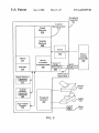
FIG. 3 is a block diagram depicting a more detailed
tracking information using the card reader 26, the key pad
example of a gaming peripheral in accordance With this
22, and the ?orescent display 26. During the game, the
player vieWs game information using the video display 34.
invention.
Usually, during the course of a game, a player is required to
make a number of decisions Which affect the outcome of the
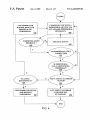
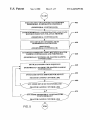
FIG. 4 is a How diagram depicting the gaming peripheral
poWer-up and communication process With the master gam
game. The player makes these choices using the player input
sWitches 32. During certain game events, the gaming
ing controller.
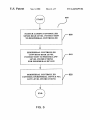
FIG. 5 is a How diagram depicting the post poWer-up
machine 2 may display visual and auditory effects that can
be perceived by the player. These effects add to the excite
communication phase betWeen the gaming peripheral and
master gaming controller.
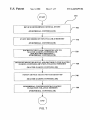
FIG. 6 is a How diagram depicting the details of a general
10
communication process of a peripheral device via a standard
peripheral interface as presented in FIG. 5.
FIG. 7 is a How diagram depicting the details of a general
event transaction as presented in FIG. 5.
15
lights behind the front glass 16 on the top box 6 or from
lights behind the belly glass 40. After the player has com
DESCRIPTION OF THE PREFERRED
EMBODIMENTS
pleted a game, the player may receive game tokens from the
coin tray 38 or the ticket 20 from the printer 18, Which may
be used for further games. Further, the player may receive a
ticket 20 for food, merchandise, or games from the printer
18.
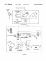
FIG. 2 is a block diagram depicting a gaming peripheral
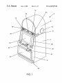
Turning ?rst to FIG. 1, a video gaming machine 2 of the
present invention is shoWn. Machine 2 includes a main
cabinet 4, Which generally surrounds the machine interior
(not shoWn) and is vieWable by users. The main cabinet
includes a main door 8 on the front of the machine Which
opens to provide access to the interior of the machine.
Typically, the main door 8 and/or any other portals Which
ment of a game, Which makes a player more likely to
continue playing. Auditory effects include various sounds
that are projected by the speakers 10, 12, 14. Visual effects
include ?ashing lights, strobing lights or other patterns
displayed from lights on the gaming machine 2 including
and its connection to a master gaming controller. The master
25
gaming controller 200 shoWn in FIG. 2 is housed Within the
main cabinet 4 of the gaming machine 2 shoWn in FIG. 1.
provide access to the interior of the machine utiliZe a locking
The master gaming controller 200 controls one or more
mechanism of some sort as a security feature to limit access
games played on the gaming machine 2. Typically, the
to the interior of the gaming machine. Attached to the main
door are player input sWitches 32, a coin acceptor 28, and a
bill validator 30, a coin tray 38, a belly glass 40, and a
monitor mask 42. VieWable through the main door is a video
“back plane” 202, Which is attached to the back of the main
cabinet 4 of the gaming machine 2. The back plane 202 may
display monitor 34 and an information panel 36. The display
monitor 34 Will typically be a cathode ray tube, high
resolution ?at-panel LCD, or other conventional electroni
cally controlled video monitor. The information panel 36 is
a back-lit, silk screened glass panel With lettering to indicate
general game information including, for example, the num
master gaming controller is connected to a mother board or
include an acceptor (not shoWn) for mechanically engaging
or latching to the master gaming controller 200 and a root
expansion hub 206 containing one or more standard com
munications ports 208. The standard communication ports
35
communication ports.
The standard communication ports 208, root expansion
ber of coins played. The bill validator 30, player input
sWitches 32, video display monitor 34, and information
hub 206, hub 210 and hub 230 and the connections to the
devices comprise a communication system that alloWs the
master gaming controller 200 to communicate With devices
connected to this system. The devices and the connections
shoWn in the ?gure are only one embodiment of the present
invention. Typically, a device is not required to be plugged
panel are devices used to play a game on the game machine
2. The devices are controlled by circuitry (not shoWn)
housed inside the main cabinet 4 of the machine 2. Many
possible games, including traditional slot games, video slot
games, video poker, keno, and lottery, may be provided With
gaming machines of this invention.
into a particular port. Examples of devices, Which might be
45
The gaming machine 2 includes a top box 6, Which sits on
top of the main cabinet 4. The top box 6 houses a number of
remote hub 210, a coin acceptor 216, a bill validator and a
gaming peripheral 228. These devices may be housed Within
the main cabinet 4 of the gaming machine 2 or may reside
outside of the main cabinet 4. Other examples of devices
tracking information, and a card reader 26 for entering a
Which might incorporate a standard communication port 208
that communicate With the master gaming controller 200,
include the coin hopper 212, the bill validator 214, the coin
magnetic striped card containing player tracking informa
55
acceptor 216, the button panel 218, the light array 236, the
printer 238, the card reader 240, the camera 242, in FIG. 2
and the speaker 10 Which is part of an audio system, the
circuitry (not shoWn) housed Within the main cabinet 4 of the
machine 2. Peripheral control circuitry in top box 6 also
display screen 34, the information panel 36, the key pad 22
in FIG. 1. These devices might be connected directly to the
mother board 202 containing the root expansion hub 206
provides some control functions for the top box devices. The
top box 6 is designed to be removable from the machine 2.
Typically, the top box 6 is replaced to repair a device Within
using one or more of the standard communication ports 208
or through one or more devices containing standard com
the top box 6 or to install a neW top box 6 With a different
set of devices.
When a user Wishes to play the gaming machine 2, he or
she inserts cash through the coin acceptor 28 or bill validator
30. At the start of the game, the player may enter playing
connected to a root expansion hub 206 With standard com
munication ports 208 on a mother board 202 With a master
gaming controller 200, include ?ber optic conversion 204, a
devices including speakers 10, 12, 14, a glass panel With
display lamps 16, a ticket printer 18 Which prints bar-coded
tickets 20, a key pad 22 for entering player tracking
information, a ?orescent display 24 for displaying player
tion. The top box 6 may house different or additional devices
than shoWn in the FIGS. 1 and 2. The devices housed in the
top box 6 add features to a game played on the machine 2.
During a game, these devices are controlled, in part, by
208 are used to connect to other devices containing standard
65
munication ports, Which are connected to the root expansion
hub 206 on the mother board 202. For example, the coin
hopper 212 is connected to a standard communication port
222 on the bill validator 214. The bill validator 214 is
connected to the root expansion hub 206 on the mother