1
Distributed by
Any reference to Raytheon or
RTN in this manual should be
interpreted as Raymarine.
The names Raytheon and RTN
are owned by the
Raytheon Company.
USER’S GUIDE
D
Noo.. 8811220077__11
meenntt N
Dooccuum
FFeebbrruuaarryy 22000022
RayTech
Navigator 4.0
R
Raayym
maarriinnee,, IInncc..
FFFttt... LLLaaau
o
n
D
n
g
n
n
g
E
d
u
d
on
n
gD
Diiivvviiisssiiio
ng
giiin
neeeeeerrriiin
En
ng
daaallleee E
ud
deeerrrd
ttthhh
9
S
t
.
0
0
N
W
4
1
8
1
NW
W4
49
9 S
Stt..
18
80
00
0N
FFFttt... LLLaaau
9
3
3
3
0
d
u
d
30
09
9
33
33
ud
deeerrrd
daaallleee FFFLLL 3
S
A
U
U
US
SA
A
w
w
w
w
m
n
o
m
ww
ww
w...rrraaayyym
maaarrriiin
neee...ccco
om
m
vi
D
DIISSC
CLLA
AIIM
ME
ER
RSS A
AN
ND
DW
WA
AR
RR
RA
AN
NTTYY
WARNING: This electronic chart is an aid to navigation designed to facilitate the use of authorized
government charts, not to replace them. Only official government charts and notices to mariners contain
all of the current information needed for the safety of navigation, and the captain is responsible for their
prudent use.
The program and its charts do NOT excuse the user from carrying the required official charts
and documents.
Raymarine, Inc., ("Raymarine") does not warrant that this Product is error free or that it is compatible
with products manufactured by any person or entity other than Raymarine.
This Product utilizes digital chart data, and electronic information from the Global Positioning System
("GPS") and weather information which may contain errors. Raymarine does not warrant the accuracy of
such information and you are advised that errors in such information may cause the product to malfunction
or give incorrect readings. Raymarine is not responsible for damages or injuries caused by your use or
inability to use the Product, by the interaction of the Product with products manufactured by others or by
errors in chart data or information utilized by the Product provided by third parties.
Except for the limited warranty regarding the magnetic media contained in the license agreement
accompanying the Product, this Product is provided "AS IS" without warranty of any kind, either
express or implied, including but not limited to the implied warranties of merchantability and fitness
for a particular purpose, and any others which may arise from course of performance, course of dealing,
or usage of trade.
WARNING: Nautical navigation is an inherently dangerous undertaking and should only be engaged in
by persons trained and experienced in navigation. This Product is intended for use only by persons
trained in nautical navigation and only as a navigational aid, not as the sole method of navigation.
NOTICE: You may not use this Product unless you agree to the terms of the license agreement. By
pressing the button titled "I AGREE", you agree to be bound by the terms of the license agreement and to
release and hold Raymarine harmless from and against any and all claims, obligations, and liabilities with
respect to the Product, except those specifically reserved in the license agreement. If you do not agree with
the terms of the license agreement, press the button entitled "I DO NOT AGREE" and the program will
exit. If you choose this option you may return the program within thirty (30) days of the date of purchase
by following the instructions contained in the license agreement.
First Edition, February 2002 Document Number: 81207_1
Copyright ©, Raymarine, Inc., 2002 All Rights Reserved.
Windows and NT are registered trademarks of Microsoft, Inc. Pentium is a registered trademark of Intel.
NVIDIA and GeForce are trademarks or registered trademarks of NVIDIA, Corp. Maptech is a registered trademark
of Maptech. C-Map and C-Map NT are registered trademarks of C-Map SRL. SeaTalk is a trademark of Nautech
Limited. Raymarine is a registered trademark, and Navigator is a trademark, of Raymarine, Inc. All other product
names mentioned are trademarks or registered trademarks (if applicable) of their respective companies. RayTech
Navigator has been licensed subject to a license agreement between you and Raymarine, Inc. Under copyright laws,
use of this manual is intended for the original licensee. No portion of this manual may be reproduced or transmitted
in any form by any means, electronic or mechanical, including photocopying, recording, or information storage and
retrieval systems, for any purpose other than the licensee’s use, without express written permission of Raymarine, Inc.,
and provided in the licensing agreement between you and Raymarine, Inc.
Printed in the U.S.A.
ii
A
Ab
bo
ou
utt T
Th
hiiss U
Usseerr’’ss G
Gu
uiid
dee
G
Deessccrriippttiioonn
Guuiiddee D
This User’s Guide describes how to install and operate Raymarine’s
RayTech Navigator marine navigation software. It assumes that the
PC on which the software will be installed meets the requirements for
running Navigator (see Chapter 2 for details), and that all peripheral
equipment that you intend to operate concurrently with Navigator has
been installed and is fully operational and compatible. In many cases,
you will be directed to refer to the user manual(s) that came with your
peripheral devices for specific installation/operation instructions.
This Guide is intended for users with varying technical and nautical
backgrounds, but assumes a general level of PC and related software
environment experience, as well as a moderate knowledge of nautical
terminology and practices. Certain portions of Navigator and this
Guide are targeted toward the experienced sailor, and these areas
are clearly identified as such.
TTeecchhnniiccaall A
Accccuurraaccyy
The technical and graphical information contained within this User’s
Guide, to the best of our knowledge, was correct at the time of printing.
However, Raymarine’s policy of continuous product improvement and
updating may change product specifications and operating nature with
out prior notice. As a result, unavoidable differences between the
product and this Guide may occur from time to time, liability for
which cannot be accepted by Raymarine.
iii
C
Coonnvveennttiioonnss
This section explains and gives examples of the writing conventions and margin symbols
used within this Guide.
G
Coonnvveennttiioonnss
Geenneerraall C
Ø
Text that represents items you see on the screen are shown
in this font. For example:
On the Polars screen, click the Polar tab.
Ø
Text that represents text you are required to type-in is shown
in this font. For example:
Point your browser to www.raymarine.com.
Ø
When you are required to access/choose items from drop-down
menus, the word select is used. Menus levels are shown
separated by a forward slash “/”. For example:
From the File menu, select Setup/System.
Ø
When you are required to “press a button” on the screen,
the word click is used. For example:
Click Apply to plot new variables after editing.
M
Maarrggiinn SSyym
mbboollss
Ø
Ø
symbol in a margin it means there is an
When you see the
important Note worth reading within the accompanying text.
When you see the
symbol in a margin it can indicate a tip,
words to the wise, or simply some additional, useful information.
iv
P
Prro
od
du
ucctt T
Teecch
hn
niiccaall S
Su
up
pp
po
orrtt
This section gives National and International telephone numbers, email
and surface mail addresses, and an Internet address for use should you
encounter any difficulties while using RayTech Navigator.
TTeelleepphhoonnee ((U
Sttaatteess))
Unniitteedd S
Toll-Free:
1-800-539-5539 X2333
Standard:
1-603-881-5200 X2333
FAX:
1-603-864-4756
TTeelleepphhoonnee ((E
Euurrooppee))
Telephone:
+44 (0)23 9271 4713
FAX:
+44 (0)23 9266 1228
E
Addddrreessss
maaiill A
Em
[email protected]
M
Maaiilliinngg A
Addddrreesssseess
United States:
Raymarine, Inc.
22 Cotton rd, Unit D
Nashua, NH 03063-4219
Europe:
Raymarine Ltd
Anchorage Park
Portsmouth, Hampshire
England PO3 5TD
IInntteerrnneett
www.raymarine.com
v
vi
T
Taab
bllee o
off C
Co
on
ntteen
nttss
C
Chhaapptteerr 11 -- IInnttrroodduuccttiioonn.................................................................... 11--11
W
Naavviiggaattoorr....................................................11--11
RaayyTTeecchh N
mee ttoo R
Weellccoom
EEaassyy M
Waayyppooiinnttss .......... 11--22
Roouutteess aanndd W
Ussiinngg R
Naavviiggaattiioonn U
Maarriinnee N
M
maattss ffoorr FFlleexxiibbiilliittyy.................................................................. 11--22
Chhaarrtt FFoorrm
Muullttiippllee C
C
Reeppoorrttiinngg.................. 11--33
Occeeaannooggrraapphhiicc R
Weeaatthheerr//O
mpprreehheennssiivvee W
Coom
AAddvvaanncceedd G
wiitthh
Usseerr IInntteerrffaaccee w
Grraapphhiiccaall U
C
Diissppllaayyss.............................................................................. 11--44
miizzaabbllee TToooollbbaarrss//D
Cuussttoom
®
®
®
IInntteeggrraatteess w
Raayytthheeoonn’’ss SSeeaaTTaallkk aanndd
wiitthh R
N
Deevviicceess ........................................................................ 11--55
Ouuttppuutt D
Daattaa O
MEEAA 00118833 D
NM
33--D
Diissppllaayy.................................................................................................................. 11--55
Coonnttoouurr D
DC
O
Moodduulleess ................................................................................................11--66
Oppttiioonnaall M
SSaaiill R
Moodduullee........................................................................................................................ 11--66
Raacceerr M
FFiisshhiinngg PPrroo M
Moodduullee...................................................................................................................... 11--77
C
Chhaapptteerr 22 -- IInnssttaalllliinngg tthhee S
Sooffttw
waarree…
…....…
…....................22--11
O
Ovveerrvviieew
w ..........................................................................................................................22--11
B
Beeffoorree Y
Yoouu B
Beeggiinn ................................................................................................22--11
H
Haarrddw
waarree R
Reeqquuiirreem
meennttss...................................................................................................... 22--22
SSeettttiinngg YYoouurr PPC
CM
Moonniittoorr’’ss C
Coolloorrss ffoorr BBeesstt D
Diissppllaayy........................ 22--22
IInnssttaallliinngg N
Naavviiggaattoorr............................................................................................22--33
IInnssttaallliinngg FFrroom
CD
D.................................................................................................................. 22--33
m aa C
IInnssttaallliinngg FFrroom
m tthhee IInntteerrnneett.............................................................................................. 22--99
vii
RayTech Navigator User’s Guide
C
Chhaapptteerr 33 -- U
Ussiinngg N
Naavviiggaattoorr''ss IInntteerrffaaccee ................ 33--11
O
w.......................................................................................................................... 33--11
Ovveerrvviieew
M
Deessccrriippttiioonnss .......................... 33--11
mppoonneenntt D
Coom
Maaiinn IInntteerrffaaccee C
D
Meennuuss............................................................................................ 33--33
wnn M
Doow
Drroopp--D
FFiillee M
Meennuu .................................................................................................................................................. 33--33
W
Meennuu ................................................................................................................................ 33--33
Waayyppooiinntt M
R
Meennuu............................................................................................................................................ 33--44
Roouuttee M
TToooollss M
Meennuu ............................................................................................................................................ 33--44
TToooollss//PPrree--SSttaarrtt M
Meennuu .............................................................................................................. 33--55
VViieew
Meennuu .............................................................................................................................................. 33--55
wM
W
Meennuu .................................................................................................................................... 33--66
wM
Wiinnddoow
H
Meennuu................................................................................................................................................ 33--66
Heellpp M
TToooollbbaarrss............................................................................................................................ 33--77
SSttaannddaarrdd TToooollbbaarr............................................................................................................................ 33--77
W
Roouutteess TToooollbbaarr.................................................................................... 33--77
Waayyppooiinntt aanndd R
C
Chhaarrttiinngg TToooollbbaarr ............................................................................................................................ 33--88
AAllaarrm
mss TToooollbbaarr.................................................................................................................................. 33--88
AAnniim
maattiioonn TToooollbbaarr........................................................................................................................ 33--99
TTiiddeess//C
Cuurrrreennttss TToooollbbaarr.......................................................................................................... 33--99
33--D
D VViieew
w TToooollbbaarr..........................................................................................................................33--1100
FFiisshhiinngg TToooollbbaarr ..............................................................................................................................33--1100
YYaacchhtt R
Raacciinngg TToooollbbaarr............................................................................................................33--1111
PPrree--SSttaarrtt TToooollbbaarr..........................................................................................................................33--1111
W
Weeaatthheerr TToooollbbaarr ..........................................................................................................................33--1111
PPaatthhffiinnddeerr PPaanneell TToooollbbaarr..................................................................................................33--1122
FFuunnccttiioonnbbaarr M
Meennuuss ...................................................................................... 33--1122
x
viii
Table of Contents
SSttaannddaarrdd FFuunnccttiioonnbbaarr.......................................................................................................... 33--1122
R
R
B
Rooouuuttteee B
Buuuttttttooonnn..............................................................................................................................................................................................................................333---111444
G
B
G
Buuuttttttooonnn....................................................................................................................................................................................................................................333---111444
Goootttooo B
M
B
M
Buuuttttttooonnn..............................................................................................................................................................................................................................333---111444
Maaarrrkkksss B
T
B
M
T
Buuuttttttooonnn.....................................................................................................................................................................333---111555
Mooorrreee""" B
Toooppp---LLLeeevvveeelll """M
S
B
M
S
Buuuttttttooonnn.........................................................................................................................................................333---111555
Mooorrreee""" B
Seeecccooonnnddd---LLLeeevvveeelll"""M
F
B
F
Buuuttttttooonnn..........................................................................................................................................................................................................................................333---111666
Fiiillleee B
W
B
m
A
W
Buuuttttttooonnn..................................................................................................................................................................333---111666
maaatttiiiooonnn B
Annniiim
Weeeaaattthhheeerrr A
S
B
S
Buuuttttttooonnn.................................................................................................................................................................................................................................333---111777
Seeetttuuuppp B
R
Raaddaarr FFuunnccttiioonnbbaarr.................................................................................................................... 33--1177
H
B
M
H
Buuuttttttooonnn.......................................................................................................................................................................................333---111999
Mooodddeee B
Heeeaaadddiiinnnggg M
.
.
n
o
t
t
u
B
s
t
e
g
r
a
T
T
Buuttttoonn......................................................................................................................................................................................................................333---111999
Taarrggeettss B
M
B
M
Buuuttttttooonnn..............................................................................................................................................................................................................................333---111999
Maaarrrpppaaa B
G
B
G
Buuuttttttooonnn....................................................................................................................................................................................................................................333---222000
Gaaaiiinnn B
V
B
B
E
M
R
V
Buuuttttttooonnnsss ......................................................................................................................................................................................................333---222111
BLLL B
EB
M///E
RM
VR
T
B
T
Buuuttttttooonnn....................................................................................................................................................................................................................................333---222222
Tuuunnneee B
SSoonnaarr FFuunnccttiioonnbbaarr.................................................................................................................... 33--2222
F
B
F
Buuuttttttooonnn.........................................................................................................................................................................................................333---222444
Frrreeeqqquuueeennncccyyy B
Z
Z
m
B
Zoooooom
mB
Buuuttttttooonnn.................................................................................................................................................................................................................................333---222444
B
B
m
B
Booottttttooom
m LLLoooccckkk B
Buuuttttttooonnn................................................................................................................................................................................................333---222555
A
A
S
B
A---S
Scccooopppeee B
Buuuttttttooonnn..................................................................................................................................................................................................................333---222555
V
V
R
M
E
B
B
VR
RM
M///E
EB
BLLL B
Buuuttttttooonnnsss ......................................................................................................................................................................................................333---222666
A
A
m
B
Alllaaarrrm
mB
Buuuttttttooonnn.................................................................................................................................................................................................................................333---222777
C
Cuussttoom
miizziinngg tthhee IInntteerrffaaccee....................................................................33--2288
U
Ussiinngg tthhee C
Cuussttoom
miizzee D
Diiaalloogg BBooxx ........................................................................ 33--2288
C
C
m
m
T
Cooom
mm
maaannndddsss T
Taaabbb..................................................................................................................................................................................................................333---222999
T
T
T
Taaabbb..............................................................................................................................................................................................................................333---333000
Toooooolllbbbaaarrrsss T
K
T
K
Taaabbb...........................................................................................................................................................................................................................333---333222
Keeeyyybbboooaaarrrddd T
M
T
M
Taaabbb.............................................................................................................................................................................................................................................333---333333
Meeennnuuu T
O
T
O
Taaabbb....................................................................................................................................................................................................................................333---333444
Oppptttiiiooonnnsss T
ix
RayTech Navigator User’s Guide
C
Chhaapptteerr 44 -- W
Woorrkkiinngg W
Wiitthh C
Chhaarrttss aanndd R
Roouutteess 44--11
O
w.......................................................................................................................... 44--11
Ovveerrvviieew
IInnssttaallliinngg C
Chhaarrttss.................................................................................................... 44--11
AAbboouutt U
Naavviiggoottoorr.................................................................... 44--11
Wiitthh N
Chhaarrttss W
Ussiinngg C
W
Chhaarrttss............................................................................................................ 44--22
Whheerree ttoo SSttoorree C
IInnssttaallliinngg M
Chhaarrttss............................ 44--22
OAAAA//BBSSBB C
NO
CXX aanndd N
MaappTTeecchh PPC
W
Roouutteess .................................................................................... 44--66
Wiitthh R
Woorrkkiinngg W
C
Roouuttee............................................................................................................................ 44--77
Crreeaattiinngg aa R
EEddiittiinngg R
Waayyppooiinnttss..................................................................................44--1100
Roouutteess aanndd W
W
D
M
A
B
W
Deeellleeetttiiinnnggg.........................................................444---111000
Mooovvviiinnnggg,,, aaannnddd D
Addddddiiinnnggg,,, M
Baaasssiiicccsss::: A
Waaayyypppoooiiinnnttt B
M
W
M
Waaayyypppoooiiinnntttsss ..........................................................................................................................................................................................444---111888
Mooodddiiifffyyyiiinnnggg W
S
W
R
S
Waaayyypppoooiiinnntttsss...............................................................................................................................................................444---222000
Reeelllaaatttiiivvveee W
Seeettttttiiinnnggg R
a
W
h
t
i
W
g
n
i
k
r
o
W
G
W
Grrrooouuupppssssss....................................................................................................................................444---222222
Waayyypppoooiiinnnttt G
Wiitthh W
Woorrkkiinngg W
U
B
R
W
U
Biiinnn.......................................................................................................................................444---222666
Reeecccyyycccllleee B
Waaayyypppoooiiinnnttt R
Usssiiinnnggg ttthhheee W
C
Naavviiggaattoorr FFuunnccttiioonnss.... 55--11
Addvvaanncceedd N
Chhaapptteerr 55 -- A
O
Ovveerrvviieew
w.......................................................................................................................... 44--11
U
Ussiinngg R
Raaddaarr W
Wiitthh N
Naavviiggaattoorr................................................................ 55--11
D
Diissppllaayyiinngg tthhee R
Raaddaarr SSccrreeeenn........................................................................................ 55--33
D
Diissppllaayyiinngg tthhee ""TToopp LLiinnee"" SSttaattuuss H
Heeaaddeerr.................................................... 55--33
D
Diissppllaayyiinngg tthhee C
Coonnttrrooll PPaanneell ........................................................................................ 55--44
U
Ussiinngg tthhee PPaatthhffiinnddeerr PPaanneell TToooollbbaarr.................................................................... 55--55
U
Ussiinngg tthhee R
Raannggee C
Coonnttrrooll.................................................................................................... 55--66
C
R
C
Raaannngggeee...................................................................................................................................................................................................555---666
Chhhaaannngggiiinnnggg ttthhheee R
T
S
R
T
S
Raaannngggeee S
Scccaaallleee..................................................................................................................................................................555---777
Stttaaannndddaaarrrddd R
Thhheee S
D
R
R
m
A
D
Raaadddaaarrr R
Raaannngggeee.......................................................................................................................................555---888
Accctttuuuaaalll R
miiinnniiinnnggg A
Deeettteeerrrm
x
viii
Table of Contents
IInntteerrpprreettiinngg aanndd AAddjjuussttiinngg tthhee R
Raaddaarr PPiiccttuurree ........................................ 55--99
IIddeennttiiffyyiinngg FFaallssee EEcchhoo R
Reettuurrnnss.............................................................................. 55--1100
S
S
Siiidddeee LLLooobbbeeesss.......................................................................................................................................................................................................................................555---111111
IIInnndddiiirrreeecccttt (((F
E
F
Eccchhhoooeeesss.................................................................................................................................................................................555---111111
Faaalllssseee))) E
M
E
M
Eccchhhoooeeesss..................................................................................................................................................................................................................555---111222
Muuullltttiiipppllleee E
B
E
w
S
S
B
Effffffeeecccttt..........................................................................................................................................555---111222
wE
Shhhaaadddooow
Seeeccctttooorrrsss ooorrr S
Bllliiinnnddd S
R
Coonnttrrooll.................................................................................................................. 55--1133
Gaaiinn C
Raaddaarr G
SSeeaa C
Coonnttrrooll.................................................................................................................. 55--1144
Clluutttteerr C
R
Coonnttrrooll................................................................................................................ 55--1166
Clluutttteerr C
Raaiinn C
TTuunniinngg tthhee R
Reecceeiivveerr .............................................................................................................. 55--1188
C
Diissppllaayy .................................................................................... 55--1199
Chhaannggiinngg tthhee TTaarrggeett D
IIInnnttteeerrrfffeeerrreeennnccceee R
R
Reeejjjeeeccctttiiiooonnn....................................................................................................................................................................................555---222000
T
E
T
Exxxpppaaannnsssiiiooonnn.........................................................................................................................................................................................................555---222000
Taaarrrgggeeettt E
T
W
T
Waaakkkeeesss...........................................................................................................................................................................................................................555---222111
Taaarrrgggeeettt W
M
M//EEBBLL.......................... 55--2211
RM
Ussiinngg VVR
Raannggee aanndd BBeeaarriinngg U
Meeaassuurriinngg R
M
V
m
T
B
R
M
Veeesssssseeelll....................................555---222333
mV
Taaarrrgggeeettt fffrrrooom
Beeeaaarrriiinnnggg tttooo T
Raaannngggeee aaannnddd B
Meeeaaasssuuurrriiinnnggg R
U
B
E
M
R
V
U
BLLL ...............................................................................................................................................................................................................555---222333
EB
M///E
RM
VR
Usssiiinnnggg V
M
B
E
M
R
V
M
BLLL................................................................................................................................................................................................555---222444
EB
M///E
RM
VR
Mooovvviiinnnggg aaa V
PPllaacciinngg M
Maarrkkss.................................................................................................................................. 55--2255
IInnrroodduuccttiioonn ttoo M
MAAR
RPPAA........................................................................................................ 55--2266
S
S
N
Saaafffeeetttyyy N
Noootttiiiccceeesss........................................................................................................................................................................................................................555---222666
R
R
A
m
Riiissskkk A
Asssssseeessssssm
meeennnttt............................................................................................................................................................................................................555---222777
T
T
D
Taaarrrgggeeettt D
Daaatttaaa....................................................................................................................................................................................................................................555---222777
T
a
r
g
e
t
V
T
H
Taarrggeett V
Veeeccctttooorrr aaannnddd H
Hiiissstttooorrryyy.....................................................................................................................................................................555---222888
R
R
R
S
Raaadddaaarrr R
Raaannngggeee S
Scccaaallleeesss..........................................................................................................................................................................................555---222888
A
A
M
A
R
P
A
T
Acccqqquuuiiirrriiinnnggg aaa M
MA
AR
RP
PA
AT
Taaarrrgggeeettt............................................................................................................................................................555---222999
D
T
R
P
A
M
A
D
PA
AT
Taaarrrgggeeettt..................................................................................................................................................................555---333000
MA
AR
RP
Deeellleeetttiiinnnggg aaa M
U
B
A
D
A
R
P
M
U
Boooxxx................................................................................................................................................555---333000
RP
PA
AD
Diiiaaallloooggg B
MA
AR
Usssiiinnnggg ttthhheee M
ix
RayTech Navigator User’s Guide
U
Ussiinngg S
Soonnaarr W
Wiitthh N
Naavviiggaattoorr............................................................ 55--3322
PPaatthhffiinnddeerr PPaanneell ffoorr SSoonnaarr............................................................................................55--3333
FFiisshh IInnddiiccaattiioonnss..............................................................................................................................55--3333
E
S
B
F
E
Spppeeeeeeddd..................................................................................................................555---333555
Boooaaattt S
Frrreeeqqquuueeennncccyyy aaannnddd B
Effffffeeecccttt ooofff F
BBoottttoom
m IInnddiiccaattiioonnss......................................................................................................................55--3355
D
D..............................................................................................................................55--3366
Deepptthh TTaarrggeett IID
SSeelleeccttiinngg tthhee BBaacckkggrroouunndd C
Coolloorr............................................................................55--3377
C
Chhaannggiinngg tthhee SSccrroolll SSppeeeedd............................................................................................55--3377
AAddjjuussttiinngg tthhee R
Coonnttrrooll........................................................................................55--3399
Raannggee C
SSeelleeccttiinngg tthhee PPoow
weerr SSeettttiinngg ........................................................................................55--4400
SSeelleeccttiinngg tthhee FFrreeqquueennccyy....................................................................................................55--4400
AAddjjuussttiinngg tthhee D
Gaaiinn ((SSeennssiittiivviittyy))......................................................55--4411
Diissppllaayy G
AAddjjuussttiinngg tthhee C
Gaaiinn....................................................................................................55--4422
Coolloorr G
U
Ussiinngg tthhee AA--SSccooppee ....................................................................................................................55--4433
U
m LLoocckk....................................................................................................................55--4444
Ussiinngg BBoottttoom
U
Whhiittee LLiinnee..............................................................................................................55--4455
Ussiinngg tthhee W
U
m..........................................................................................................................................55--4455
Ussiinngg ZZoooom
U
Ussiinngg AAllaarrm
mss......................................................................................................................................55--4466
U
Ussiinngg VVR
RM
M............................................................................................................................................55--4477
U
Ussiinngg W
Waayyppoonnttss............................................................................................................................55--4499
U
Ussiinngg P
Poollaarrss ttoo O
Oppttiim
miizzee Y
Yoouurr P
Peerrffoorrm
maannccee.......... 55--5500
C
Coollleeccttiinngg D
Daattaa................................................................................................................................55--5511
E
Enntteerriinngg aanndd E
Eddiittiinngg D
Daattaa.................................................................. 55--5511
PPoollaarrss PPaarraam
meetteerrss SSccrreeeenn ............................................................................................55--5522
D
Daattaa TTeessttss SSccrreeeenn......................................................................................................................55--5544
H
Poollaarr P
Plloott................................ 55--5599
Reeaadd aa P
w ttoo G
Grraapphh aanndd R
Hoow
U
MC
C PPlloott SSccrreeeennss ........55--6622
wnnw
wiinndd,, aanndd VVM
Doow
Uppw
wiinndd,, D
Ussiinngg tthhee U
x
viii
Table of Contents
C
Caalliibbrraattiinngg ttoo E
Ennssuurree D
Daattaa A
Accccuurraaccyy..................................55--6655
BBooaatt SSppeeeedd C
Caalliibbrraattiioonn...................................................................................................... 55--6655
C
Caalliibbrraattiioonn............................................................................................................ 55--6666
mppaassss C
Coom
AAppppaarreenntt W
Caalliibbrraattiioonn........................................................................ 55--6666
Wiinndd AAnnggllee C
TTrruuee W
Caalliibbrraattiioonn...................................................................................... 55--6677
Wiinndd AAnnggllee C
TTrruuee W
Caalliibbrraattiioonn.................................................................................... 55--6699
Wiinndd SSppeeeedd C
U
Paanneell ......................................55--7700
meenntt P
Ennggiinnee IInnssttrruum
Ussiinngg tthhee E
D
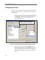
Diissppllaayyiinngg tthhee PPaanneell.............................................................................................................. 55--7711
C
Coonnffiigguurriinngg tthhee PPaanneell.......................................................................................................... 55--7722
A
A -Appppeennddiixx A
C
A--11
meennttss ......................A
Peerriipphheerraall IInnssttrruum
Coonnnneeccttiinngg P
ix
C
Ch
haap
ptteerr 11
IIn
nttrro
od
du
uccttiio
on
n
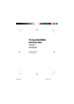
Welcome to RayTech Navigator
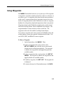
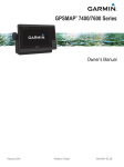
This User’s Guide describes how to use Raymarine®’s RayTech
Navigator marine navigation software (Figure 1-1). RayTech
Navigator operates within a standard Windows® environment, and
enables you to utilize the latest digital charts and Global Positioning
System (GPS) instrumentation to help you pilot your vessel to virtually
anywhere in the world. Navigator easily interfaces with your boat’s
onboard navigational systems, offering you the flexibility to allow
Navigator to autopilot your vessel to any destination you choose to
plot. Navigator also incorporates the capability to download the latest
weather and oceanographic information and display it on any chart,
thus keeping you apprised of foul weather near you or your destination.
Furthermore, Navigator is the perfect choice for the serious sailor
or fisherman, offering advanced optional modules that enhance
Navigator’s route-plotting and fish-finding performance. The subsections that follow detail the sophisticated capabilities and features of
RayTech Navigator.
Figure 1-1. Typical RayTech Navigator Chart Screen
1-1
RayTech Navigator User’s Guide
Easy Marine Navigation Using Routes and Waypoints
RayTech Navigator takes the guesswork out of marine navigation by
enabling you to easily chart, plot, and execute simple or complex
routes. A route is composed of a series of waypoints that you select
on the screen, with each waypoint denoting a certain position along
the path of the route. A route typically has a starting waypoint and an
ending waypoint, and as many intermediate waypoints as you need or
want. Using Navigator, you can create a route to any destination with
a few simple clicks of the mouse, and then follow it manually or
enable your vessel’s autopilot to follow the route/waypoints you have
designated. Routes and waypoints can easily be changed “on the fly,”
should weather or other factors necessitate a change in course.
Multiple Chart Formats for Flexibility
Navigator uses the latest digitized versions of the paper charts
traditionally used in marine navigation, and supports a variety of
popular chart formats:
• C-Map® NT
• Maptech® NOAA/BSB
• Maptech PCX
• Maptech Photo Regions and Topographical Charts
• SoftCharts® Nautical Charts and PhotoNavigator
These charts fall into three basic types:
• Vector –
1-2
A paper chart that has been digitized
into a format consisting of line segments.
Vector charts can be easier to read than
a rasterized chart, but may not include
the level of detail found in Raster charts.
The C-MAP chart is an example of a
vector chart.
Introduction
• Raster –
A paper chart that has been scanned into
a high resolution image. A raster chart
has the advantage of being virtually
identical to the original paper chart from
which it was scanned. The MapTech
NOAA/BSB and PCX charts are
examples of raster charts.
• Aerial Imagery – A high resolution, geo-referenced rasterized
photograph taken from aerial or satellite
sources. You can overlay your vessel’s
position on such an image, and get a
visual estimation of your position with
reference to actual, photography-based
landmarks. The MapTech Photo Region
chart is an example of an aerial imagery
chart.
Comprehensive Weather/Oceanographic Reporting
Navigator offers you the capability to download and display the latest
weather and ocean conditions, and then superimpose this information
upon your charts in several layers. Weather and oceanographic (sea
tides and currents) files (in GRIB format) can be downloaded directly
from the internet or requested via email. After you have acquired your
files, you can fully animate them to show the predicted weather and
ocean currents over a specified period of time. Typical weather files
contain information in 6, 12, and 24 hour intervals, covering a period
of several days. Navigator can further break this information down
into intervals as small as 30 minutes, giving you a comprehensive
presentation of atmospheric and marine conditions.
1-3
RayTech Navigator User’s Guide
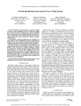
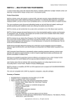
Advanced Graphical User Interface with
Customizable Toolbars/Displays
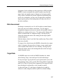
You operate Navigator via an easy-to-use Graphical User Interface
(GUI) complete with many customizable Toolbars, Function bars, and
“floating” Databoxes (Figure 1-2). Using an intuitive menu hierarchy,
you can display only those tools that you commonly use, or customize
screens to show you only pertinent information, with just a few mouse
clicks. You can zoom deeply into charts to display the maximum level
of detail for the region you are in, animate weather and oceanographic
files to monitor the meteorological events in your area, and create
comprehensive logs containing virtually every piece of data that you
might encounter and collect on a voyage. Navigator’s flexible GUI
enables you to tailor its powerful resources to suit your needs quickly
and easily.
Toolbars, Function bars, and Databoxes can
be moved and displayed anywhere you need
them
Figure 1-2. Navigator’s Toolbars, Functionbars, and Databoxes
1-4
Introduction
Integrates with Raymarine’s SeaTalk® and NMEA 0183
Data Output Devices
Navigator is designed to work transparently with Raymarine’s SeaTalk
data communications package, or any other device that outputs data
in NMEA 0183 format. This enables parameters such as Heading,
Wind Speed/Direction, Sea Temperature, and a variety of others to be
accessed and displayed within Navigator. Navigator can also connect
to such onboard systems as Ockam, B&G, and KVH via a standard
RS-232 data cable. This enables the information collected by
Navigator to be relayed and displayed on your vessel’s standard
onboard instrumentation systems.
Navigator also connects to Radar systems that are capable of
outputting Cursor Range and Bearing, and also to ARPA Radar
systems. This allows targets identified by Radar to be plotted on
directly onto Navigator’s chart displays. You can also connect
Navigator to a variety of proprietary instruments, and generate
comprehensive log files which can then be analyzed from within
Navigator or saved and exported for future external analysis.
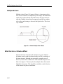
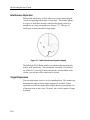
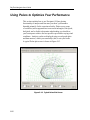
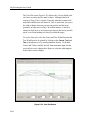
3-D Contour Display
Navigator’s advanced 3-D Contour Display shows your vessel, the
ocean floor, and other related information using a 3-D vector-style
display. This enables you to view any area, such as favored fishing
and sailing spots, harbor entrances, and so forth, within a full, 3dimensional window. Images can be rotated 360° so you can view
your vessel’s position from virtually an angle. 3-D Contour gives you
useful navigational perspectives that you might not be able to ascertain
from a conventional display.
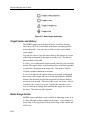
The 3-D Contour Display includes:
• Past navigational markers
• Depth markers
• Transducer cone images
1-5
RayTech Navigator User’s Guide
Optional Modules
RayTech Navigator offer two comprehensive optional modules to
increase Navigator’s capabilities: Sail Racer and Fishing Pro.
Sail Racer Module
Navigator’s Sail Racer Module is targeted toward the professional
sailboat racer, and includes DataTrak, Polars, Route Optimization,
Advanced Weather Routing, Pre Start display, Navigation Numbers,
and a specialized Racing toolbar.
• DataTrak is an instrument-recording program that captures a
variety of incoming navigational and performance-related data
and displays it on time-based graphs in multiple windows.
• Polars uses a group of variables (such as apparent/true/
corrected wind angles, boat speed, heel/pitch, and so forth)
to determine what heading you should set your boat upon to
achieve the best possible speed under varying wind conditions.
Analysis results are displayed using multiple graph plots which
you can modify (edit) to suit your needs.
• Route Optimization determines your ideal route based upon
ocean current, wind speed and direction, in addition to your
vessel’s Polar characteristics, then plots this route upon the
chart you desire.
• Advanced Weather Routing consists of detailed, 7-day
animated weather files, text-based advisories for North
American coastal regions, and offshore forecasts/advisories.
• The Racing toolbar displays special icons that are used within
racing environments such as The America’s Cup, and enables
you to set marks and courses quickly and accurately based upon
GPS or laser-guided input.
1-6
Introduction
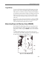
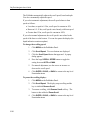
Fishing Pro Module
The Fishing Pro Module enables you to use Navigator to easily locate
the world’s best fishing areas using up-to-the-minute, satellite-based
oceanographic data.
The module includes:
• The latest ocean temperature data presented as overlays
upon your navigational charts to aid you in finding the
warmer locations where fish may be hiding.
• Plankton content areas of the ocean presented as overlays
upon your navigational charts so that you can easily
identify clear, fish filled waters.
• 3-D bathymetric charts to precisely identify ocean bottom
contours, enabling you to readily pinpoint the areas where
fish are more likely to concentrate.
• Complete engine monitoring capability, which displays
a realistic on-screen gauge cluster (including tachometer,
oil pressure, turbocharger boost, and more). This feature
allows you to easily check your vessel’s engine-related
systems from within Navigator.
1-7
C
Ch
haap
ptteerr 22
IIn
nssttaalllliin
ng
g tth
hee S
So
offttw
waarree
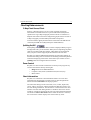
Overview
This chapter explains how to install RayTech Navigator onto your PC,
and contains the following:
• Minimum and recommended system requirements
• How to set your PC to display Navigator in optimal color
• Installing Navigator from CD-ROM
• Installing Navigator from the Internet
Note: How to connect external devices such as GPS,
Radar/Sonar, and autopilots is explained in
Appendix A, “Connecting Peripheral Instruments.”
Before You Begin
Before you can begin installing Navigator, you need to make sure that
the PC you intend to use meets the minimum hardware requirements
for running the software. This subsection lists the minimum and
recommended hardware requirements that your PC must comply
with to properly run Navigator. It also explains how to set your PC
to display the best color scheme within Navigator, and also how to
connect any peripheral devices (instruments) that you may have.
2-1
RayTech Navigator User’s Guide
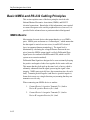
Hardware Requirements
This subsection lists the minimum hardware requirements that your
PC must conform to in order to run Navigator properly.
While Navigator is designed to run successfully on the minimum
configuration, we also include a recommended hardware setup that
ensures optimal performance from the Navigator software.
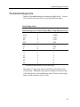
Minimum System Requirements:
• Pentium® III
• 64MB of RAM
• 100MB available free space on your disk drive
• Monitor capable of displaying 640 x 480 resolution
• CD ROM drive
• Windows 98/ME/2000/XP (will not run on Windows 95/NT4)
Recommended System Requirements:
• Pentium III or higher
• 128MB of RAM or more
• NVIDIA® GeForce graphics card
• Windows 2000/XP
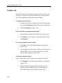
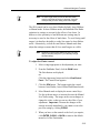
Setting Your PC Monitor’s Colors for Best Display
To fully utilize Navigator’s color display properties, we recommend
that you set your PC’s monitor to the highest color display/resolution
setting that it can support above 256-colors. (It is important to note
that Navigator will not run if 256-colors, or less, are selected.)
This is typically done by displaying the Desktop Properties screen in
Windows (right-click the mouse with the cursor on your desktop),
then clicking the Settings tab. Choose the highest color setting your
monitor and PC can handle. Refer to your PC/Windows user manual
for more information about setting display colors and resolution.
2-2
Installing the Software
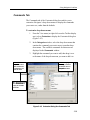
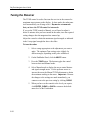
Installing Navigator
The steps you follow to install Navigator depend upon whether you
are installing from a CD or from Raymarine’s Web site on the
Internet. Both of these methods are explained in this section, and both
consist of a short sequence of installation wizard screens containing
simple steps that you must complete. After you have successfully
installed Navigator, you will need your Navigator License Key(s).
A License Key is a sequence of digits and characters you enter initial
configuration (explained later in this chapter) to activate Navigator
and enable its various options modules. You need a unique License
Key for Navigator, and one for each optional module you are adding.
These keys can be purchased for immediate use on the Raymarine
Web site.
The subsections that follow explain how to install Navigator.
Installing From a CD
To install Navigator from a CD:
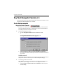
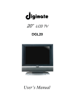
1.
Insert the CD into your PC. After a moment or two,
the InstallShield Wizard Welcome screen (Figure 2-1)
is displayed.
2-3
RayTech Navigator User’s Guide
Figure 2-1. InstallShield Wizard Welcome Screen
2.
Click Next. The InstallShield Wizard (ISW) License
Agreement screen (Figure 2-2) is displayed. This screen
contains Navigator’s Licensing Agreement/Legal Disclaimers.
Click I accept… , then
click Next to continue
Figure 2-2. InstallShield Wizard License Agreement Screen
2-4
Installing the Software
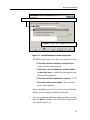
3.
Make our Legal Department happy by reading all the text,
then click the checkbox beside “I accept …” and click Next
to display the ISW Customer Information screen (Figure 2-3).
Type your name and organization,
set access, then click Next to continue
Figure 2-3 InstallShield Wizard Customer Information Screen
4.
Type the name of the person and the organization to whom
this version of Navigator is being licensed, then choose
whether you want Navigator to be used just by that specific
individual or by anyone with access to the computer. Click
Next to display the ISW Setup Type screen (Figure 2-4).
2-5
RayTech Navigator User’s Guide
Select the installation setup you want,
then click Next to continue
Figure 2-4 InstallShield Wizard Setup Type Screen
The ISW Setup Type screen allows you to choose which
components of Navigator you want installed. The choices
are as follows:
Ø Complete – Installs Navigator and all subcomponents
Ø Custom –
5.
Installs only the Navigator subcomponents
you choose (A selection screen is displayed
after you pick this option and click Next.)
Click Complete or Custom, then click Next to continue.
If you select Complete, skip to Step 10.
If you select Custom, continue with this step.
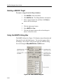
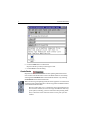
The ISW Custom Setup screen (Figure 2-5) is displayed,
and enables you to select the Navigator components you
want installed. As shown in Figure 2-5, select the
drop-down menu beside a component, then choose an
installation approach from the displayed menu items.
2-6
Installing the Software
First, click drop-down menu beside component, then, choose the method of installation
Click Space to check the space available on your drives
Figure 2-5. InstallShield Wizard Custom Setup Screen
The ISW Custom Setup screen choices are defined as follows:
Ø This feature will be installed on local hard drive –
installs selected component only
Ø This feature, and all subfeatures, will be installed
on local hard drive – installs selected component and
all related subcomponents
Ø This feature will be installed when required – ?????
Ø This feature will not be available – does not install
the selected component
Keep in mind that you need a License Key for each Optional
Module you are installing in addition to Navigator.
6.
Select the components and the installation methods you want,
then click Next to continue. The ISW Ready to Install screen
is displayed (Figure 2-6).
2-7
RayTech Navigator User’s Guide
Figure 2-6. InstallShield Wizard Ready to Install Screen
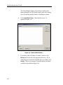
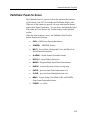
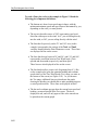
7.
Click Install on the ISW Ready to Install screen to begin the
installation. The progress of the installation is displayed on
the screen, and after a few moments, the ISW Completed
screen (Figure 2-7) appears.
8.
Click Finish to complete the installation.
Figure 2-7. InstallShield Wizard Completed Screen
2-8
Installing the Software
Installing From the Internet
Installation from Raymarine’s Web site is very similar to installing
from a CD.
To install Navigator from the Internet, do the following:
1.
Point your Internet browser to:
www.raymarine.com/raytech
2.
Follow the instructions on the screen to download Navigator.
2-9
C
Ch
haap
ptteerr 33
U
Ussiin
ng
gN
Naavviig
gaatto
orr’’ss IIn
ntteerrffaaccee
Overview
This chapter shows you around Navigator’s user interface, illustrating
and explaining the functions and components of the following:
• Navigator main interface
• Main drop-down menus
• Toolbars
• Functionbars (Standard, Radar, and Sonar)
The sections that follow give you details about all drop-down menu
hierarchies/submenus and how to access them, as well as how to
display the various Toolbars and Functionbars and what they do.
All menu levels and functions are illustrated and described,
enabling you to work smoothly and efficiently within Navigator.
Main Interface Component Descriptions
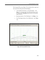
This section illustrates the main user interface, and identifies its
various components. The interface is composed of standard dropdown and pop-up menus, Toolbars and Functionbars. You simply
point-and-click to access most functions, and you can right-click on
most any component to display context-sensitive help. Toolbars and
Functionbars can be moved around the Navigator screens and charts
(by clicking and dragging), and “docked” (positioned) wherever you
need them to display. Navigator retains your settings from session to
session, and re-displays the interface the same way each time.
3-1
RayTech Navigator User’s Guide
Figure 3-1. Navigator’s Main Interface
3-2
Using Navigator’s Interface
Drop-Down Menus
This section shows each of the main interface drop-down menus
(File, Waypoint, etc. — Figures 3-2 through 3-9) and gives brief
functional descriptions of each menu item.
File Menu
Figure 3-2. File Drop-Down Menu Item Descriptions
Waypoint Menu
Figure 3-3. Waypoint Drop-Down Menu Item Descriptions
3-3
RayTech Navigator User’s Guide
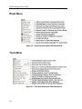
Route Menu
Figure 3-4. Route Drop-Down Menu Item Descriptions
Tools Menu
Figure 3-5. Tools Drop-Down Menu Item Descriptions
3-4
Using Navigator’s Interface
Tools/Pre-Start Menu
Figure 3-6. Tools/Pre-Start Drop-Down Menu Item Descriptions
View Menu
Figure 3-7. View Drop-Down Menu Item Descriptions
3-5
RayTech Navigator User’s Guide
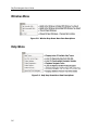
Window Menu
Figure 3-8. Window Drop-Down Menu Item Descriptions
Help Menu
Figure 3-9. Help Drop-Down Menu Item Descriptions
3-6
Using Navigator’s Interface
Toolbars
This section shows each of the Toolbars (Standard, Charting, etc. —
Figures 3-10 through 3-21) and gives brief functional descriptions of
each Toolbar item.
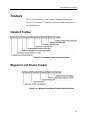
Standard Toolbar
Figure 3-10. Standard Toolbar Item Descriptions
Waypoints and Routes Toolbar
Figure 3-11. Waypoints and Routes Toolbar Item Descriptions
3-7
RayTech Navigator User’s Guide
Charting Toolbar
Figure 3-12. Charting Toolbar Item Descriptions
Alarm Toolbar
Figure 3-13. Alarm Toolbar Item Descriptions
3-8
Using Navigator’s Interface
Animation Toolbar
Figure 3-14. Animation Toolbar Item Descriptions
Tides/Currents Toolbar
Figure 3-15. Tides/Currents Toolbar Item Descriptions
3-9
RayTech Navigator User’s Guide
3-D View Toolbar
Figure 3-16. 3-D View Toolbar Item Descriptions
Fishing Toolbar
Figure 3-17. Fishing Toolbar Item Descriptions
3-10
Using Navigator’s Interface
Yacht Racing Toolbar
Figure 3-18. Yacht Racing Toolbar Item Descriptions
Pre-Start Toolbar
Figure 3-19. Pre-Start Toolbar Item Descriptions
Weather Toolbar
Figure 3-20. Weather Toolbar Item Descriptions
3-11
RayTech Navigator User’s Guide
Pathfinder Panel Toolbar
Figure 3-21. Pathfinder Toolbar Item Descriptions
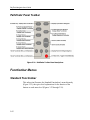
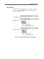
Functionbar Menus
Standard Functionbar
This subsection illustrates the Standard Functionbar’s menu hierarchy
(Figure 3-22), then gives brief explanations for the function of the
buttons on each menu level (Figures 3-23 through 3-30).
3-12
Using Navigator’s Interface
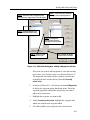
Figure 3-22. Standard Functionbar Menu Hierarchy
3-13
RayTech Navigator User’s Guide
Route Button
Figure 3-23. Functionbar Route Button Descriptions
Goto Button
Figure 3-24. Functionbar Goto Button Descriptions
Marks Button
Figure 3-25. Functionbar Marks Button Descriptions
3-14
Using Navigator’s Interface
Top-Level “More” Button
Figure 3-26. Functionbar Top-Level “More” Button Descriptions
Second-Level “More” Button
Figure 3-27. Functionbar Second-Level “More” Button Descriptions
3-15
RayTech Navigator User’s Guide
File Button
Figure 3-28. Functionbar File Button Descriptions
Weather Animation Button
Figure 3-29. Functionbar Weather Animation Button Descriptions
3-16
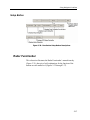
Using Navigator’s Interface
Setup Button
Figure 3-30. Functionbar Setup Button Descriptions
Radar Functionbar
This subsection illustrates the Radar Functionbar’s menu hierarchy
(Figure 3-31), then gives brief explanations for the function of the
buttons on each menu level (Figures 3-32 through 3-37).
3-17
RayTech Navigator User’s Guide
Figure 3-31. Radar Functionbar Menu Hierarchy
3-18
Using Navigator’s Interface
Heading Mode Button
Figure 3-32. Radar Functionbar Heading Mode Button Descriptions
Targets Button
Figure 3-33. Radar Functionbar Targets Button Descriptions
Marpa Button
Figure 3-34. Radar Functionbar Marpa Button Descriptions
3-19
RayTech Navigator User’s Guide
Gain Button
Figure 3-35. Radar Functionbar Gain Button Descriptions
3-20
Using Navigator’s Interface
VRM/EBL Buttons
The VRM/EBL Functionbar buttons can only be accessed in an
open Radar window by clicking the VRM/EBL button on the
Pathfinder Panel Toolbar — see Figure 3-21.
Figure 3-36. Radar Functionbar VRM/EBL Button Descriptions
3-21
RayTech Navigator User’s Guide
Tune Button
The Tune Functionbar button can only be accessed in an open Radar
window by clicking the MULTI button on the Pathfinder Panel Toolbar
— see Figure 3-21.
Figure 3-37. Radar Functionbar Tune Button Descriptions
Sonar Functionbar
This section illustrates the Sonar Functionbar’s menu hierarchy
(Figure 3-38), then gives brief explanations for the function of the
buttons on each menu level (Figures 3-39 through 3-44).
3-22
Using Navigator’s Interface
Figure 3-38. Sonar Functionbar Menu Hierarchy
3-23
RayTech Navigator User’s Guide
Frequency Button
Figure 3-39. Sonar Functionbar Frequency Button Descriptions
Zoom Button
Figure 3-40. Sonar Functionbar Zoom Button Descriptions
3-24
Using Navigator’s Interface
Bottom Lock Button
Figure 3-41. Sonar Functionbar Bottom Lock Button Descriptions
A-Scope Button
Figure 3-42. Sonar Functionbar A-Scope Button Descriptions
3-25
RayTech Navigator User’s Guide
VRM/EBL Buttons
The VRM/EBL Functionbar buttons can only be accessed in an open
Sonar window by clicking the VRM/EBL button on the Pathfinder
Panel Toolbar — see Figure 3-21.
Figure 3-43. Sonar Functionbar VRM/EBL Button Descriptions
3-26
Using Navigator’s Interface
Alarm Buttons
The Alarm Functionbar buttons can only be accessed in an open Sonar
window by clicking the ALARMS button on the Pathfinder Panel
Toolbar — see Figure 3-21.
Figure 3-44. Sonar Functionbar Alarm Button Descriptions
3-27
RayTech Navigator User’s Guide
Customizing the Interface
This section describes how you can tailor Navigator’s interface to
display only the information you require. It explains how use the
Customize dialog box to modify and personalize the following areas
of Navigator:
• Drop-down menu commands
• Toolbars
• Keyboard input
• Toolbar and Menu display appearance
• Toolbar and Menu display behavior
Using the Customize Dialog Box
This subsection illustrates the Customize dialog box and also shows
and explains how to use its various tabs (Figures 3-45 through 3-49).
Each tab displays a different set of options and parameters, enabling
you to alter the appearance and behavior of many parts of Navigator’s
interface to better suit your needs.
3-28
Using Navigator’s Interface
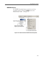
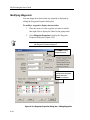
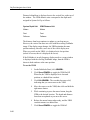
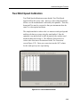
Commands Tab
The Commands tab of the Customize dialog box enables you to
customize Navigator’s drop-down menus to display the commands
you want to see, rather than the defaults.
To customize drop-down menus:
STEP 1.
Select the
drop-down menu
that contains the
command(s) you
want to move
1.
From the View menu (or right-click near the Toolbar display
area), select Customize to display the Customize dialog box
(Figure 3-45).
2.
In the Categories window, select the drop-down menu that
contains the command you want to move to another dropdown menu. The available commands for that menu are
displayed in the Commands window.
3.
Highlight the command you want to add, then drag it over
to the name of the drop-down menu you want to add it to.
STEP 2.
Highlight
and drag command
to desired menu in
Categories window
TIP:
Scroll down and
select All Commands to
display all available
commands
Figure 3-45. Customize Dialog Box Commands Tab
3-29
RayTech Navigator User’s Guide
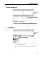
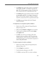
Toolbars Tab
The Toolbars tab of the Customize dialog box enables you to restore
Navigator’s Toolbars to their factory default states, and also allows
you to create and name (and rename) custom Toolbars.
To display the Toolbars tab:
1.
From the View menu (or right-click near the Toolbar display
area), select Customize to display the Customize dialog box.
2.
Click the Toolbars tab (Figure 3-46).
To reset Toolbars to original default settings:
1.
Check the box(es) beside the Toolbar(s) you want to reset
2.
Click Reset; or if you want to reset all the Toolbars at once,
click Reset All.
To create and name a custom Toolbar:
1.
Click New. The Toolbar Name dialog box is displayed
(Figure 3-46).
2.
Type the name you want for the Toolbar (up to 50 characters)
then click OK. The new Toolbar appears in the Toolbar
window and also appears on the screen.
To rename a custom Toolbar:
(Only Toolbars that you have created can be renamed or deleted.)
3-30
1.
Click Rename. The Toolbar Name dialog box is displayed
(Figure 3-46).
2.
Type the new name you want for the Toolbar (up to 50
characters) then click OK. The new Toolbar appears in
the Toolbar window and also appears on the screen.
Using Navigator’s Interface
Click button to
perform desired
operation on Toolbar
Check the Toolbars
you want to display
or modify
Figure 3-46. Customize Dialog Box Toolbars Tab
3-31
RayTech Navigator User’s Guide
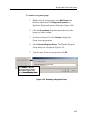
Keyboard Tab
The Keyboard tab of the Customize dialog box enables you to
associate keystroke shortcuts to commonly-used commands in
Navigator. For example, to display the Layers dialog box, you might
assign the keys Ctrl+L. Then, each time you press that sequence of
keys, the Layers dialog box appears.
To associate keystrokes with commands:
1.
From the View menu (or right-click near the Toolbar display
area), select Customize to display the Customize dialog box.
2.
Click the Keyboard tab (Figure 3-47).
3.
From the Category drop-down menu, select the menu that
contains the command you want to create a shortcut for.
4.
In the Press New Shortcut Key window, type the key
sequence you want to represent the command.
5.
Click Assign to complete creating the shortcut.
STEP 1.
Select the
drop-down menu
that contains the
command you want
STEP 4.
Click Assign
TIP: Scroll down and
select All Commands to
display all commands
STEP 2. Highlight
the command you
want to shortcut
STEP 3.
Type key sequence
Figure 3-47. Customize Dialog Box Keyboard Tab
3-32
Using Navigator’s Interface
Menu Tab
The Menu tab of the Customize dialog box is currently non-functional
within Navigator; however, it will display if the tab is clicked.
Figure 3-48. Customize Dialog Box Menu Tab
3-33
RayTech Navigator User’s Guide
Options Tab
The Options tab of the Customize dialog box contains checkboxes
that control Toolbar and icon display characteristics. You can also
download a new appearance profile for the interface that changes
the “look and feel” of the controls without affecting their behavior
or command structures.
To display the Options tab:
1.
From the View menu (or right-click near the Toolbar display
area), select Customize to display the Customize dialog box.
2.
Click the Options tab (Figure 3-49).
3.
Check the items you want displayed, or to change the “look
and feel” of Navigator’s interface, click Visualizations and
follow the instructions given. Figure 3-49 shows an example
of a “before” and “after” Toolbar.
Click Visualizations
to download new
appearance profiles
for the interface
Figure 3-49. Customize Dialog Box Options Tab
3-34
C
Ch
haap
ptteerr 44
W
Wo
orrkkiin
ng
gW
Wiitth
hC
Ch
haarrttss A
An
nd
dR
Ro
ou
utteess
Overview
This chapter explains how to use RayTech Navigator to chart and
plot courses for nautical navigation. The chapter is intended to
have you navigating with the basics in the shortest possible time,
and leaves the more complex Navigator operations for Chapter 5,
“Advanced Navigator Functions.” Refer to that chapter if you
already have a working knowledge of Navigator. This chapter
covers the following areas:
• Installing, displaying, and manipulating the various chart types
• Creating, editing, and implementing waypoints and routes
• Getting and using the latest weather and oceanographic reports
Installing Charts
This section explains how to install and load the various chart types
that Navigator uses.
About Using Charts with Navigator
Navigator supports all of the popular chart types, including:
• C-Map NT
• Maptech NOAA/BSB
• Maptech PCX
• Maptech Photo Regions and Topographical Charts
• SoftCharts Nautical Charts and PhotoNavigator
Important: Navigator automatically loads a default World Chart
on each start-up. You cannot close this window or uninstall this
chart — simply open a new window over it.
4-1
RayTech Navigator User’s Guide
Working with charts in Navigator consists initially of installing the
charts, after which, you can open and display as many or as few as
you need. The more charts you decide to install, the longer the overall
installation process takes; however, once installed, you can display
those charts at the moment you need them without waiting.
It’s important to keep in mind the difference between
installing the charts into Navigator, and installing the charts
onto your PC from the original manufacturer’s CD. The chart
installation instructions in this chapter describe installation
from a Navigator point-of-view, leaving the explanation of
installing the charts onto your PC to the chart manufacturer.
Refer to the instructions that came with the CD.
Where to Store Charts
The best place to store your charts is on the hard drive of the PC that’s
running Navigator. By loading your most commonly used charts onto
the PC, you always have virtually instant access to them, they load
faster, and they are easier to read under rough conditions (CD drives
can skip tracks if tossed about). The charts, especially photographic
charts, will consume disk space, but with today’s large-Gigabyte hard
drives, it should not be an issue.
Installing MapTech PCX and NOAA/BSB Charts
To install MapTech PCX and NOAA/BSB Charts:
4-2
1.
Insert the chart CD into the PC.
2.
From the File menu, select Settings. The RayTech Settings
dialog box (Figure 4-1) is displayed.
3.
Double-click on the Raster Charts icon. Chart Manager
screen 1 is displayed (Figure 4-2).
Working With Charts And Routes
Double-click Raster Charts icon
to begin installing charts
Figure 4-1. RayTech Settings Dialog Box
Figure 4-2. Chart Manager Screen 1
4-3
RayTech Navigator User’s Guide
The Chart Manager displays all currently available raster
charts (although it will be initially empty), and is the starting
place for opening installed charts or installing new charts.
4.
Click Install New Charts. Chart Installer screen 1 is
displayed (Figure 4-3).
Figure 4-3. Chart Installer Screen 1
5.
4-4
If you know where the charts you want to load are, click
Browse and locate/select the appropriate directory. If you
want Navigator to search all available drives for charts, click
Search. After a few moments, Navigator displays all charts
available for installation (Figure 4-4).
Working With Charts And Routes
Highlight the charts you want to install, then click
Install Now. Progress is shown next to chart.
Figure 4-4. Chart Installer Screen 2
6.
Highlight the charts you want to install (or click Select All to
install every chart), then click Install Now. The progress of
each chart’s installation is shown. When the charts have been
installed, Chart Manager screen 1 is redisplayed (Figure 4-5).
Figure 4-5. Chart Manager Screen 1 Showing Installed Charts
4-5
RayTech Navigator User’s Guide
Working With Routes
This section explains how to plot and edit routes. A route is a path
from location A to location B, and is composed of a series of
waypoints that you “place” on a displayed chart. Each waypoint
represents a certain position along the path of the route. A route
typically has a starting waypoint, an ending waypoint, and as many
intermediate waypoints as you need or want.
The distance between any two waypoints is known as a leg. The leg
of the route your boat is currently traversing is called the active leg.
An active leg consists of an origin waypoint (the waypoint you just
departed) and a destination waypoint (the waypoint you are moving
toward). In Navigator, the active leg of a route is represented by a
dashed line and a blinking gray circle around the destination waypoint.
Plotting a route requires just a few mouse clicks, and you can easily
move/adjust your waypoints after placing them on the screen. Routes
can be as simple or complex as you need, and by offering a wide range
of icons and display colors, Navigator allows you to customize each
route (and individual waypoints) for easy recognition and navigation.
Navigator stores all your favorite or most commonly used routes, and
you can create several backup routes for any destination, should
inclement weather or other circumstances dictate you take a different
course. If you have Navigator connected to a GPS and Autopilot, the
route you chart on the screen can be run automatically.
Note: The subsections that follow presume that you already
have charts installed and displayed within Navigator.
4-6
Working With Charts And Routes
Creating a Route
To create and name a route:
1.
As shown in Figure 4-6, select Create Route from the
Route menu, or, click the Create Route button on the toolbar.
The Quick Route dialog box is displayed (Figure 4-7).
To start a route:
Select Create Route or
click Create Route button on toolbar
Figure 4-6. Two Ways of Starting a Route
Type a new route name,
then click OK, or just click
OK to accept default name
Figure 4-7. Quick Route Dialog Box
4-7
RayTech Navigator User’s Guide
2.
Type in a name (up to 13 characters including blanks) for
your route, or click OK to accept the default name of “Qr.”
Note: Identical route names will overwrite each other
without a confirmation warning.
3.
Click OK. The Standard cursor
changes to the Route
cursor
(Figure 4-8). Move the cursor over the area
where you want the route to begin, then left-click the mouse.
The route is started, and the name you chose along with range
and bearing of the first leg is displayed (Figure 4-8).
Distance and bearing of leg appears between waypoints
Draw Route cursor
Route name appears at originating point and at each additional waypoint
Figure 4-8. Beginning a Route
4-8
Working With Charts And Routes
4.
Draw the route you want to take. Left-click at the places
where you want to leave a waypoint marker. To remove
waypoints, click the Undo Wp button
on the
toolbar.
The route name along with the range and bearing of each leg
is displayed between each waypoint (Figure 4-9).
5.
As shown in Figure 4-9, when you reach the end of the route,
right-click and select Finish Quick Route, or just click
the Create Route button
on the toolbar.
Left-click to place waypoints
To end the route, right-click and select
Finish Quick Route, or, click the Create Route
button
on the Toolbar
Figure 4-9. Completing a Route
4-9
RayTech Navigator User’s Guide
Editing Routes and Waypoints
After you’ve completed plotting a route, you might want to make
some changes. Navigator allows you to fully manage your routes and
their waypoints, including moving/removing waypoints and routes,
working with groups of waypoints, and changing waypoint properties
(properties govern how a waypoint appears and behaves on the
screen). Editing routes and waypoints covers the following topics:
• Adding, moving, and deleting waypoints
• Modifying waypoint display characteristics
• What are, and how to place, relative waypoints
• Creating and editing waypoint groups
• Using the waypoint recycle bin
• Adding, moving, renaming, and deleting routes
Waypoint Basics: Adding, Moving, and Deleting
This subsection describes how to add waypoints to an existing route,
move/relocate waypoints on the chart, and delete waypoints.
To add a waypoint to a route:
1.
As shown in Figure 4-10, select Edit Route from
Route menu or click the Edit Route on the toolbar.
The Edit Route dialog box is displayed (Figure 4-11).
To edit a route:
Select Edit Route or
click Edit Route button
Figure 4-10. Two Ways of Displaying the Edit Route Dialog Box
4-10
Working With Charts And Routes
STEP 1.
STEP 2.
Select the route or waypoint group
that contains the waypoints you want to display
Click arrow, then select the
route you want to add waypoints to
STEP 3.
Highlight waypoint you
want to add to the selected route
STEP 4.
Highlight the
waypoint after which the
new waypoint will be added
Click >> to add
new waypoint to route
STEP 5.
Click checkbox to display
selected route all the time
Figure 4-11. Edit Route Dialog Box: Adding a Waypoint to a Route
If the route you want to add waypoints to is not the currently
active route, you’ll need to select it as shown in Figure 4-11.
The waypoints associated with the currently selected route
are displayed in the window directly beneath Currently
active route.
2.
As shown in Figure 4-11, click the arrow beneath Waypoints
to display the waypoint group drop-down menu. Select the
waypoint group that contains the waypoint(s) you want to
add to the selected route.
3.
Highlight the waypoint you want to add.
4.
Under Currently active route, highlight the waypoint after
which you want the new waypoint added.
5.
Click >> to add the new waypoint to the selected route.
4-11
RayTech Navigator User’s Guide
To move (relocate) a waypoint:
1.
As shown in Figure 4-12, place the cursor over the waypoint
you want to move, then press and hold the left mouse button.
2.
Move the cursor to the position on the chart where you want
the waypoint moved, then release the button. The waypoint
moves to the new location.
To move a waypoint:
Place cursor over
waypoint, press and hold
the left mouse button,
then move to new
location and release
Figure 4-12. Moving a Waypoint
4-12
Working With Charts And Routes
To move the waypoint you’re heading toward to your vessel’s
current position:
1.
As shown in Figure 4-13, select Move Destination to Vessel
from the Waypoint menu, or, click Marks/Dest to Vessel on
the function bar.
The waypoint you are approaching is moved to your vessel’s
current location.
Figure 4-13. Moving the Waypoint You Are Approaching To The Vessel
To move the waypoint you’re heading away from to your vessel’s
current position:
1.
As shown in Figure 4-14, select Move Origin to Vessel from
the Waypoint menu, or, click Marks/Origin to Vessel on the
function bar.
The waypoint you are heading away from is moved to your
vessel’s current location.
Figure 4-14. Moving the Waypoint You Are Leaving To The Vessel
4-13
RayTech Navigator User’s Guide
To put a new waypoint at your vessel’s current position:
1.
As shown in Figure 4-15, select Place Waypoint at Vessel
from the Waypoint menu, or, click Marks/Wpt at Vessel
on the function bar.
The Waypoint At Vessel information dialog box appears
(Figure 4-16). The dialog box shows the time the waypoint
is added, and has a space where you can type relevant information, such as location, water depth and temperature, etc.
2.
Type your information into work space (optional), then click
OK to place new waypoint on the chart.
Figure 4-15. Placing A Waypoint At The Vessel’s Current Position
Figure 4-16. Waypoint At Vessel Information Dialog Box
4-14
Working With Charts And Routes
To put a new waypoint at the cursor’s current position:
1.
As shown in Figure 4-17, click Marks/Wpt at Cursor on the
function bar (this function cannot be accessed from the
Waypoints drop-down menu).
The Standard cursor
2.
changes to the Route cursor
.
Place the cursor where you want the new waypoint, then
left-click. The new waypoint appears on the chart.
Figure 4-17. Placing A Waypoint At The Cursor’s Current Position
4-15
RayTech Navigator User’s Guide
To put a man overboard waypoint at the vessel’s current position:
1.
As shown in Figure 4-18, select Place Waypoint at Cursor
from the Waypoint menu, click MOB on the toolbar, or
click More/More/Man Overboard on the function bar.
The man overboard marker is placed automatically at the
vessel’s current position, Navigator calculates the most direct
route back to the marker, and automatically makes that route
the active route.
Figure 4-18. Placing A Man Overboard Marker
4-16
Working With Charts And Routes
To delete a waypoint from a route:
1.
Place the cursor over the waypoint you want to delete,
then right-click to display the Chart Action popup menu
(Figure 4-19).
2.
Select Delete Waypoint. The waypoint is removed from
the chart.
Note: You can also delete waypoints from the Waypoint
Properties dialog box. Refer to “Modifying
Waypoints” later in this section.
Right-click on waypoint to
display Chart Action popup,
then select Delete Waypoint
Figure 4-19. Deleting a Waypoint
4-17
RayTech Navigator User’s Guide
Modifying Waypoints
You can change how/where/when any waypoint is displayed by
editing the Waypoint Properties dialog box.
To modify a waypoint’s display characteristics:
1.
Place the cursor over the waypoint you want to modify,
then right-click to display the Chart Action popup menu.
2.
Select Waypoint Properties to display the Waypoint
Properties dialog box (Figure 4-20).
Note: You can also double-click on a waypoint to display
the Waypoint Properties dialog box.
Click Groups to display
Group Action menu
Drop-down menu for
setting relative waypoints
appears whenever
Pinged is unchecked
Figure 4-20. Waypoint Properties Dialog Box: Editing Waypoints
4-18
Working With Charts And Routes
The Waypoints Properties dialog box contains the following:
• Group Name field –Name of waypoint group.
• Groups button – Displays group action menu (Fig. 4-20).
• Waypoint Name field – Name of waypoint.
• Rename button – Click to rename waypoint.
• Latitude field – Latitude coordinate of waypoint.
• Range field – Displayed only if Relative box is checked
and Pinged box is unchecked. Displays range of
waypoint in Metric or English units. Refer to “Setting
Relative Waypoints” for more information.
• Locked checkbox – If checked, waypoint cannot be
accidentally dragged from its chart insertion point.
• Longitude field – Longitude coordinate of waypoint.
• Bearing field – Displayed only if Relative box is
checked and Pinged box is unchecked. Displays
bearing of waypoint in Metric or English units. Refer
to “Setting Relative Waypoints” for more information.
• Show on Chart checkbox – If checked, waypoint is
displayed on chart
• Notes window – Additional information about waypoint.
• Range Circles checkbox – If checked, range circles are
displayed around waypoint.
• Radius (NM) field –Range Circle radius in Nautical Miles.
• Number field – Number of Range Circles displayed.
• Relative checkbox – If checked, enables you to place a
waypoint that remains relative to another waypoint.
Refer to “Setting Relative Waypoints” for more details.
• Pinged checkbox – Refer to “Setting Relative Waypoints”
for more information.
4-19
RayTech Navigator User’s Guide
• Relative waypoint drop-down menu – Displayed only if
Relative box is checked and Pinged box is unchecked.
Choose the waypoint you want the current waypoint to
be relative-to — refer to “Setting Relative Waypoints”
for more information.
• Marker icons display window – Displays the various
icons you can use to represent the waypoint.
• New button – Adds a new waypoint to the group.
• Delete button – Deletes the waypoint from the group.
Setting Relative Waypoints
This subsection explains how to set a waypoint so that it is always
displayed the same relative distance from another waypoint.
To set one waypoint as relative to another:
4-20
1.
As explained previously, create two waypoints, or, decide
which two existing waypoints you want to use. For the sake
of this example, we’ll call the first waypoint WP1 and the
second WP2.
2.
On the chart, double-click WP2. The Waypoint Properties
dialog box is displayed (Figure 4-20).
3.
Click the Relative checkbox. The Pinged checkbox appears
to the right of the Relative checkbox.
4.
Click the Pinged checkbox to “uncheck” it. The Pinged
checkbox disappears and a drop-down menu with a list of
waypoint names appears. Observe that the Latitude
and Longitude fields also switch to Range and Bearing,
respectively.
5.
Click the drop-down menu, and select WP1 from the list.
Working With Charts And Routes
6.
In the Range field, type the range at which you want WP2 to
remain relative from WP1. For example, if you enter 300
miles, WP2 will always remain at a range of 300 miles from
WP1, no matter where WP1 is repositioned on the chart.
7.
In the Bearing field, type the bearing at which you want WP2
to remain relative from WP1. For example, if you enter 90
degrees, WP2 will always remain at a bearing of 90 degrees
from WP1, no matter where WP1 is repositioned on the chart.
8.
Click OK to save your changes and close the Waypoint
Properties dialog box.
To temporarily set one waypoint to specific coordinates:
1.
Double-click on WP2 to display the Waypoint Properties
dialog box (Figure 4-20).
2.
Make sure that the Relative and Pinged boxes are checked.
3.
Type the specific coordinates for WP2 into the Latitude
and Longitude fields.
4.
Click OK to close and save your settings. WP2 is then
displayed at the new coordinates, while WP remains in its
originally position. The previous relative settings for WP2
are stored by Navigator, so you can return the waypoint to its
relative setting when needed..
To return a waypoint to its relative coordinates:
1.
Double-click on WP2 to display the Waypoint Properties
dialog box (Figure 4-20).
2.
Click the Pinged box to uncheck it.
3.
From the drop-down that appears, select WP1.
4.
Click OK close and return WP2 to its relative coordinates.
4-21
RayTech Navigator User’s Guide
Working With Waypoint Groups
You can create as many different groups of waypoints as you need,
and then manipulate the individual waypoints within those groups.
Waypoint groups can be added/deleted/renamed just like individual
waypoints, and waypoints can be swapped between groups, sent-to
and retrieved-from the Waypoint Recycle Bin.
To create a new waypoint group:
1.
Select Edit Route from the Route menu, then click Waypoint
Properties to display the Waypoint Properties dialog box
(Figure 4-20).
2.
As shown in Figure 4-20, click Groups to display the
Group Action popup menu.
3.
Select New Waypoint Group. The Rename Waypoint Group
dialog box is displayed (Figure 4-21).
4.
Type the name for the new group, then click OK.
Click Groups on Waypoint
Properties dialog to display
Group Action popup, then
select New Waypoint Group
Figure 4-21. Creating a New Waypoint Group
4-22
Working With Charts And Routes
To rename a waypoint group:
1.
Double-click on a waypoint (or select Edit Route from
the Route menu, then click Waypoint Properties) to
display the Waypoint Properties dialog box (Figure 4-20).
2.
Click the Group Name drop-down menu, then select the
group you want to rename.
3.
As shown in Figure 4-20, click Groups to display the
Group Action popup menu.
4.
Select Rename Waypoint Group. The Rename Waypoint
Group dialog box is displayed (Figure 4-22).
5.
Type the name for the new group, then click OK.
Click Groups on Waypoint
Properties dialog to display
Group Action popup, then
select Rename Waypoint Group
Figure 4-22. Renaming a Waypoint Group
4-23
RayTech Navigator User’s Guide
To delete a waypoint group:
1.
Double-click on a waypoint (or select Edit Route from
the Route menu, then click Waypoint Properties) to
display the Waypoint Properties dialog box (Figure 4-20).
2.
Click the Group Name drop-down menu, then select the
group you want to delete.
3.
Click Groups to display the Group Action popup menu.
4.
Select Delete Waypoint Group. A dialog box appears
(Figure 4-23) warning you that deleting a waypoint group
also deletes the waypoints that group shares with others
(if any) — use care.
5.
Click Yes to delete the waypoint group.
Click Groups on Waypoint
Properties dialog to display
Group Action popup, then
select Delete Waypoint Group
Figure 4-23. Deleting a Waypoint Group
4-24
Working With Charts And Routes
To display or hide a waypoint group:
1.
Double-click on a waypoint (or select Edit Route from
the Route menu, then click Waypoint Properties) to
display the Waypoint Properties dialog box (Figure 4-20).
2.
Click the Group Name drop-down menu, then select the
group you want to delete.
3.
Click Groups to display the Group Action popup menu.
4.
Select Show Group on Chart to display the waypoints, or
Hide Group on Chart to remove them. A confirmation
dialog appears (Figure 4-24).
5.
Click OK to show or hide the waypoints.
Click Groups on Waypoint
Properties dialog to display
Group Action popup, then
select Show Group on Chart
or Show Group on Chart to
display or hide the waypoints
Figure 4-24. Showing or Hiding a Waypoint Group
4-25
RayTech Navigator User’s Guide
Using the Waypoint Recycle Bin
When you delete waypoints, they are placed into a recycle bin from
which you can later (in the same Navigator session) retrieve them if
you need to. It’s important to keep in mind that the waypoint recycle
bin is emptied, permanently deleting all waypoints it contains, each
time you restart Navigator.
To retrieve waypoints from the recycle bin:
1.
Select Edit Route from the Route menu, then click Waypoint
Properties to display the Waypoint Properties dialog box
(Figure 4-20).
2.
As shown in Figure 4-25, click the Group Name dropdown, then select Recycle Bin from the displayed choices.
The Move Waypoints Between Groups dialog box is
displayed (Figure 4-26).
The Move Waypoints Between Groups dialog box contains
two drop-down menus that allow you to select the waypoint
groups you want to move waypoints between.
3.
From the left-most drop-down, select the waypoint group
you want to restore waypoint to (Figure 4-26).
4.
From the right-most window (the Recycle Bin), select the
waypoints you want to retrieve.
5.
Click
to retrieve and restore the waypoints.
Click drop-down, then select Recycle Bin
Figure 4-25. Selecting the Recycle Bin
4-26
Working With Charts And Routes
STEP 1.
Click drop-down, then
select waypoint group to restore to
STEP 2.
Select waypoints you
want to retrieve from Recycle Bin
Click Move -> to
retrieve and restore waypoints
STEP 3.
Figure 4-26. Retrieving Waypoints From The Recycle Bin
4-27
C
Ch
haap
ptteerr 55
A
Ad
dvvaan
ncceed
dN
Naavviig
gaatto
orr F
Fu
un
nccttiio
on
nss
Overview
This chapter covers the more advanced Navigator functions such as
Radar and Sonar. It also includes information about using Polars
data and graphics to analyze and fine-tune your racing sailboat’s
performance.
Using Radar With Navigator
This sections explains how to use the various Radar functions within
Navigator. Data from your hsb2 Series Pathfinder Radar can be
transferred and displayed (repeated) in a Navigator. The radar
output can be displayed in a separate window or overlaid on a chart.
Connection is made from the hsb2 connection via a special cable that
inputs to a PCMCIA card in your PC
When a scanner is connected and the radar is in Transmit mode, the
radar picture provides a map-like representation of the area in which
the radar is operating. Typically, your ship’s position is at the center
of the display, and its dead ahead bearing is indicated by a vertical
heading line, known as the Ship’s Heading Marker (SHM).
The radar picture can be viewed with a variety of fixed or customized
range scales. The color of the radar returns (echoes) indicates their
intensity: the strongest returns are shown in yellow and the weaker
are shown in shades of blue. A status bar at the top of the radar image
displays range, current heading and mode indicators for the various
options you can set.
The radar display can show additional information, depending on
your currently selected options, set up selections and the data available
from other equipment. The example displays on the following pages
show some of these features.
5-1
RayTech Navigator User’s Guide
The hsb2 Series Pathfinder Plus Radar system includes the following:
• Range scales: 1/8nm to 24nm up to 72nm (scanner-dependent).
• Automatic and manual control of tuning, gain and sea clutter.
• Two Variable Range Markers (VRMs) and Electronic Bearing
Lines (EBLs), allowing target range and bearing measurements.
• Target wakes and target expansion mode.
• Add marks to record important or dangerous locations.
• 10 Target MARPA for target tracking and risk analysis.
You can use this chapter with the radar display set to simulator mode,
or on the water after you have installed and set up your hsb2 Series
Pathfinder Plus Radar system.
Note: Until you are familiar with interpreting the radar display,
you should take every opportunity to compare the
radars display patterns with visual targets, such as
other vessels, buoys and coastal structures. You should
practice harbor and coastal navigation during daylight
and in clear weather conditions.
You can identify objects using either the radar/chart overlay or the
cursor echo feature: With cursor echo on you can select an object on
the radar display, the cursor is repeated on the chart display so you can
check the objects identity.
5-2
Advanced Navigator Functions
Displaying the Radar Screen
Data from your Pathfinder PLUS Radar can be repeated in a separate
RayTech Navigator window or overlaid on a chart.
To display radar data in a separate window:
1. Make sure the radar is operational and correctly connected
to the PC.
2. Power on the radar unit.
3. Click File/Open. The Open window appears.
4. Double click the Radar icon. The radar window opens with
the radar function in Standby mode.
5. From the Pathfinder Panel, click the POWER button.
Radar data is repeated over hsb2 and displayed in the window.
To overlay radar data on top of a chart:
1.
2.
3.
4.
Open a chart for your current area.
Click the Radar Overlay button
on the
toolbar. Radar data is displayed over the chart.
Click the down arrow adjacent to the Radar Overlay window.
The transparency slider appears.
Move the transparency slider up/down to decrease/increase
the overlay's transparency over the chart.
Displaying the “Top Line” Status Header
You can display a "Top Line" header above the radar window that
shows current status of the radar display settings.
To display the Top Screen:
1.
From within the Radar Window, click the right mouse button.
2.
Select View/Top Line to toggle the Top Line on.
The informational header appears at the top of the radar
window displaying range, rings, course, heading, which
settings are set for automatic from GAIN, SEA and TUNE,
and whether Interference Rejection (IR) or Target Expansion
(EXP) have been set.
3.
Click the right mouse button and select View/Top Line again
to toggle the Top Line off. The top line header disappears
and the size of the radar window is maximized.
5-3
RayTech Navigator User’s Guide
Displaying the Control Panel
You can display a Control Panel dialog box on the outside of the radar
window, which enables you to modify a number of radar settings.
To display the Control Panel:
1.
From within the Radar Window, click the right mouse button.
2.
Select View/Control Panel. The Control Panel (Figure 5-1)
is displayed along the side of the radar window.
3.
Click the right mouse button and select View/Control Panel
again to toggle the Control Panel off. The box disappears
and the size of the radar window is maximized.
Figure 5-1. Radar Control Panel
5-4
Advanced Navigator Functions
Using the Pathfinder Panel Toolbar
The Pathfinder Panel is a special toolbar that simulates the functions
of the buttons of the hsb2 Series Radar and Fishfinder display units.
When one of the buttons is pressed, the associated soft key functions
appear in the function bar below. You can access the Pathfinder Panel
from either the View Menu or the Toolbars button on the Standard
toolbar.
When the Radar window is active, clicking the Pathfinder Panel
buttons displays the following:
•
GAIN –FTC, RAIN, SEA, and GAIN Radar
Functionbar buttons
•
VRM/EBL – VRM/EBL Radar Functionbar buttons
•
MULTI – Tune Radar Functionbar button
•
ALARMS – no effect
•
DISPLAY –Open Window dialog box
•
MARKS –Waypoint Mark Radar Functionbar buttons
•
RANGE – increases/decreases radar viewing range
•
ENTER – previous Radar Functionbar menu level
•
CLEAR – previous Radar Functionbar menu level
•
MENU – System Setup, Clear Marks, EBL, and MARPA
Setup Radar Functionbar buttons
•
POWER – toggles Radar transmit/standby modes
5-5
RayTech Navigator User’s Guide
Using the Range Control
The radar display can be viewed at various scales by using the range
(zoom) control. The shortest range scale gives a maximum range of
1/8 nautical miles, measured from the default center to the top of the
radar picture. The longest range scale gives a maximum range of
between 24 and 72 nautical miles, depending upon the type of your
scanner.
• The long range scales provide the best overview of your
vessel’s relation-ship to land masses, weather fronts and
large ship targets in or beyond view.
• The short range scales provide greater detail of the radar echoes
close to your vessel, and should be used as you approach the
coastline, harbor or other vessels in the area.
The Pathfinder Plus Radar display includes concentric range rings,
that you can use to help you to judge distances on the radar picture.
Their number and spacing are adjusted automatically if you change
the range scale.
Changing the Range
Each time you click the RANGE button on the Pathfinder Panel,
the range changes to the next available setting.
The range scale and range ring interval indicators, at the left-hand
end of the status bar, are updated whenever you change the range.
5-6
Advanced Navigator Functions
The Standard Range Scale
Details of the standard ranges are shown in the table below. You can
also customize the range scales by specifying different ranges.
Radar Range Scales
Maximum Range (nm) Number of Range Rings Range Ring Interval (nm)
0.125
0.25
0.5
0.75
2
2
4
3
0.0625
0.125
0.125
0.25
1.5
3
6
6
0.25
0.5
6
12
24*
48*
72*
6
6
6
6
6
1
2
4
8
12
* The maximum range depends on your scanner type.
The number of range rings shown in the table is the number to the
selected range. Additional range rings are displayed toward the edge
of the radar picture, at the standard ring interval for the current range,
and are visible when the center is offset.
5-7
RayTech Navigator User’s Guide
Determining Actual Radar Range
The actual maximum radar range is essentially line-of-sight, and is
limited by the height of the scanner and the height of the target as
shown below lists some range examples:
Radar Range
Antenna Height (m)
Target Height (m)
Maximum Range (nm)
3
3
7.8
3
10
10.9
5
3
8.9
5
10
12.0
Note: The ranges shown in the table are theoretical maximum
ranges. The radar horizon is greater than the optical
horizon, but the radar can only detect targets if a large
enough target is above the radar horizon.
5-8
Advanced Navigator Functions
Interpreting and Adjusting the Radar Picture
Navigational echoes may be large, small, bright or faint, depending
not only on the size of the object but also on its orientation and
surface. Different objects reflect the radar signals in different ways.
For example, vertical objects such as cliffs reflect signals better than
sloping ones such as sandbanks.
High coastlines and mountainous coastal regions can be observed at
the longest radar range. However, the first sight of land may be a
mountain several miles inland from the coastline. The actual coastline
may not appear on the radar until the vessel is close to the line of sight
distance.
The radar indication may not be similar to your visual observation; a
nearby small object may appear to be the same size as a distant large
object on the radar. However, with experience the approximate size of
different objects can be determined by the relative size and brightness
of the echoes.
Some targets, such as buoys and small boats, can be difficult to
differentiate, since they bob and toss about in the waves and do not
present a consistent reflecting surface. Consequently, these echoes
have a tendency to fade and brighten and, at times, to disappear
momentarily. Buoys and small boats often resemble each other, but
boats can usually be distinguished by their motion.
Not all radar echoes are produced by hard navigational items. Some
echoes may be received from irregularities on the surface of the water,
particularly at close range (sea clutter), or from rain or snow either
around the vessel or in the distance. In addition, some echoes may be
indirect returns to the radar scanner, providing false echoes or multiple
echoes.
The effects of many false echoes can be minimized, and the target
presentation clarified using the controls summarized below. This
section explains how to interpret the radar picture and how the
controls affect the display. It provides instructions for adjusting the
settings, describes the circumstances in which they should be adjusted,
and how they interact with each other.
5-9
RayTech Navigator User’s Guide
Controls to Adjust the Radar Picture
Control
Option
Function
Default Setting
AUTO
GAIN
Controls the strength of the target returns
SEA
Reduces sea returns
AUTO-HARBOR
RAIN
Reduces close rain or snow returns
OFF
FTC
Reduces distant rain or snow returns
OFF
SEA
SEA
Reduces sea returns
AUTO-HARBOR
MULTI
TUNE
Fine tunes the receiver
AUTO
GAIN
TARGETS
INT REJ
Turns interference rejection on/off
ON
EXPANSION
Turns target expansion on/off
OFF
WAKES
Turns wakes on/off and selects wakes length
OFF
Identifying False Echo Returns
Not all echoes are direct returns to the radar antenna. Occasionally
signals appear at positions where there is no actual target. These are
called false echoes, and may be caused by side lobes, ghost images,
indirect echoes or multiple echoes.
This subsection briefly describes the echo patterns that can be
produced by false echoes and the likely cause. It should be noted that
the radar operator, through observation, practice, and experience, can
generally detect these conditions very quickly. These effects can
usually be minimized using the radar controls.
5-10
Advanced Navigator Functions
Side Lobes
A small part of the RF energy from each transmitted pulse is radiated
outside the single narrow beam. This produces side lobe patterns,
shown in Figure 5-2. Side lobes have no effect on distant or small
surface objects; however, the echo from a large object at short range
may produce an arc on the radar screen similar to a range ring or a
series of echoes forming a broken arc. Side-lobe echoes normally
occur at ranges below 3nm, and can be reduced by adjusting the SEA
control.
Figure 5-2. Radar Side Lobe Echo Affects
Indirect (False) Echoes
There are several types of indirect echoes or ghost images (Figure 5-3).
These sometimes have the appearance of true echoes, but in general
they are intermittent and poorly defined.
Figure 5-3 Radar Indirect Echo Affects
5-11
RayTech Navigator User’s Guide
Multiple Echoes
Multiple echoes (Figure 5-4) appear if there is a large target with a
wide vertical surface at a comparatively short range. The transmitted
signal will be reflected back and forth between the target and your
own ship. Multiple echoes therefore appear beyond the true targets
echo on the same bearing, as shown in the figure below. This is not
very common.
Figure 5-4. Radar Multiple Echo Affects
Blind Sectors or Shadow Effect
Funnels and masts located near the antenna, may cause shadows.
In shadow areas beyond the obstruction there will be a reduction of
the beam intensity, although not necessarily a complete cut-off.
However, there will be a blind sector if the subtended angle is more
than a few degrees. There may also be multiple echoes that extend
behind the obstruction. This should be avoided by careful selection
of the scanner site prior to installation.
5-12
Advanced Navigator Functions
Radar Gain Control
The Gain control adjusts the level of the display of signals received
from the scanner; it is equivalent to a volume control on a radio.
The Gain control can be set either to Auto or Manual modes.
In Auto mode, the Pathfinder Plus radar optimizes the setting.
In harbors or close proximity to land different auto settings may
be necessary to cater for the effects of land clutter.
Alternatively, set both Sea Clutter and Gain to Manual mode, and then
adjust the settings to ensure that all close small targets are visible.
When the Gain control is set to Manual, you should check it every
time you change the range scale. On long range settings, the gain
should be set to give a slight speckle in the background of the radar
picture. On shorter ranges, you may wish to reduce the gain slightly to
reduce the speckle and therefore improve target definition. Do not set
the gain too low, or you may miss small or weak targets. The new
Gain mode (auto or manual) and values are also retained each time
you turn the radar off or on.
Note: Gain can only be adjusted if the control is set to
Manual adjustment. Because the SEA control affects
the gain, you may need to manually readjust it if you
manually change the Gain setting.
To adjust the Gain:
1.
Select a range appropriate to the adjustment you want to
make.
2.
From the Pathfinder Panel, click the GAIN button.
The Gain Functionbar buttons are displayed.
or
Click the right mouse button and select View/Control
Panel. The Control Panel appears.
3.
Click the GAIN Functionbar button . The button toggles
the control between Auto and Manual mode.
5-13
RayTech Navigator User’s Guide
4.
If you select Manual mode, the arrow control buttons
appear. Use the up/down arrows to increase/decrease the
Manual Gain. Important: Because the changes to the
settings are made immediately, you cannot revert to the
previous setting by clicking CLEAR.
5.
When you have set the controls to the levels you require,
press ENTER, CLEAR, or BACK to return to the default
level of soft keys.
Sea Clutter Control
Radar returns from waves around your vessel can clutter the center of
the radar picture, making it difficult to detect real targets. Sea clutter
(Figure 5-5) usually appears as multiple echoes on the display at short
range scales, and the echoes are not repetitive or consistent in position.
With high winds and extreme conditions, echoes from sea clutter may
cause dense background clutter in the shape of an almost solid disc.
Figure 5-5. Radar Sea Clutter Display
The Sea Clutter control reduces the gain level in the areas near your
vessel, extending up to 3 to 5nm depending on the wave and sea
conditions. This has the effect of reducing the sea returns to
intermittent small dots, while small targets are still visible. Gain
levels further from your vessel remain unchanged. You can use the
Gain and Sea Clutter control to help minimize the effects of side lobes.
5-14
Advanced Navigator Functions
Note: On short range scales, do not set the Sea Clutter
control so high that all clutter is removed, since this
could prevent you from seeing close-echo targets.
The SEA control can be set to Auto-Harbor (default), Auto-Offshore
or Manual mode. In Auto-Offshore mode, the Pathfinder Plus Radar
optimizes its settings to account for the effects of sea clutter. In
harbors or close proximity to land different auto settings may be
necessary to cater for the effects of land clutter. To avoid losing small
targets it is therefore advisable to set the Sea control to Auto-Harbor
mode. Alternatively, set both Sea and Gain to Manual mode then
adjust the settings to ensure that all close small targets are visible.
Note: Because the SEA control affects the gain, you may
need to manually readjust it if you manually change
the Gain setting.
To adjust Sea Clutter control:
1.
Select a range appropriate to the adjustment you want.
2.
From the Pathfinder Panel, click the GAIN button.
The Gain buttons are displayed.
or
Click the right mouse button and select View/Control
Panel. The Control Panel appears.
3.
Click the SEA button. The button toggles the control
between Auto-Harbor, Auto-Offshore and Manual mode.
4.
Select Manual mode to display the arrow control keys.
Use the up/down arrows to increase/decrease the Manual
Sea Clutter setting. The image on the screen changes as
change the value, so that you can see the effect of your
adjustment. Important: Because the changes to the
settings are made immediately, you cannot revert to the
previous setting by clicking CLEAR.
5.
When you have set the controls to the levels you require,
click ENTER, CLEAR, or BACK to return to the default
menu level of the Functionbar.
5-15
RayTech Navigator User’s Guide
Rain Clutter Control
The radar can see echoes from rain or snow. Returns from storm areas
and rain squalls consist of countless small echoes that continuously
change size, intensity, and position (Figure 5-6). These returns
sometimes appear as large hazy areas, depending on the intensity of
the rainfall or snow in the storm cell.
The RAIN and FTC controls are used to reduce this clutter, so that
targets masked by the clutter can be seen on the radar picture.
• The RAIN control is used to reduce large clutter masses around
your vessel caused by rain or snow.
• The FTC (Fast Time Constant) control is used to reduce rain
clutter at a distance from your vessel, such as that shown below.
Figure 5-6. Radar Rain Clutter Display
When the FTC control is turned up, only the leading edge of large
(rain clutter) echoes is displayed, while the effect on smaller (ship)
echoes is only slight. This means that you can also use the control on
shorter ranges to distinguish between two very close echoes on the
same bearing, which may otherwise merge and appear as one echo.
When the FTC control is turned up, the receiver is less sensitive, and
there is a reduction of background noise and fill-in returns from land
and large targets. You should therefore turn the control down when its
use is not required. Since storm cells are usually visible for long
distances due to their extreme altitude, you may wish to leave them
displayed so that you can observe the location of bad weather.
5-16
Advanced Navigator Functions
If you turn the RAIN or FTC control Off (equivalent to setting the
level to 0%), the actual setting is stored, and restored when you turn
the control on again. Keep in mind however, that RAIN and FTC are
reset to Off at power-on.
To adjust the RAIN and FTC controls:
1. Select a range appropriate to the adjustment you want to
make.
2.
From the Pathfinder Panel, click the GAIN button.
The Gain buttons are displayed.
or
Click the right mouse button and select View/Control
Panel. The Control Panel appears.
3.
Click the RAIN and FTC buttons. The buttons toggle
between ON and OFF.
4.
If you select ON , the arrow control keys appear. Use the
up/down arrows to increase/decrease the RAIN and FTC
settings.
5.
When you have set the controls to the levels you require,
click ENTER, CLEAR, or BACK to return to the default
menu level of the Functionbar.
5-17
RayTech Navigator User’s Guide
Tuning the Receiver
The TUNE control is used to fine-tune the receiver in the scanner for
maximum target returns on the display. In Auto mode, the radar tunes
itself automatically on all range scales. Raymarine recommends
that you leave the TUNE control in Auto mode.
If you set the TUNE control to Manual, you will need to adjust it
about 10 minutes after you have turned on the radar, since the required
setting changes after the magnetron has warmed up.
Adjust the control to obtain the maximum signal strength, as indicated
in the 8-step signal strength bar above the slider.
To tune the radar:
5-18
1.
Select a range appropriate to the adjustment you want to
make. The optimum Tune setting varies slightly for
different ranges, depending on the pulse width used.
2.
On the Pathfinder Panel, click the MULTI button.
3.
Press the TUNE button. The button toggles the control
between Auto and Manual mode.
4.
Select Manual mode to display the arrow control buttons
and signal-strength meter. Use the up/down arrows to
increase/decrease the Manual TUNE adjustment to obtain
the maximum reading on the meter. Important: Because
the changes to the settings are made immediately, you
cannot revert to the previous setting by clicking CLEAR.
5.
When you have set the controls to the levels you require,
click ENTER, CLEAR, or BACK to return to the default
menu level of the Functionbar.
Advanced Navigator Functions
Changing the Target Display
The Pathfinder PLUS Radar allows you to improve target visibility
by changing the following:
• Interference rejection (In Rej)
• Target expansion (Expansion)
• Target wakes (Wakes)
These controls are accessed from the Functionbar Targets Button.
To change target mode settings:
1.
Click the Targets button.
2.
Click In Rej to toggle On/Off.
3.
Click Expansion to toggle On/Off.
4.
Click Wakes to select Off, Short, Medium, or Long wakes.
5.
Click Clear Wakes to remove wakes from the screen.
You can use the buttons to change the settings of any or all the modes.
The top screen status bar updates to indicate which controls are on.
5-19
RayTech Navigator User’s Guide
Interference Rejection
Mutual radar interference is likely when two or more radar-equipped
vessels are operating within range of each other. This usually appears
as a series of small dots moving to and from the display center in a
straight line or a long, sweeping curve (Figure 5-7). This type of
interference is most noticeable at long ranges.
Figure 5-7. Radar Interference Rejection Display
The Pathfinder PLUS Radar includes a mechanism that automatically
reduces such interference. This mechanism is normally left switched
on. However, if you wish to detect the presence of other radars in the
vicinity, you can turn off the interference rejection.
Target Expansion
You can make targets easier to see by expanding them. The scanner type
determines the range at which target expansion is available. Target
expansion overrides the normal pulse length, thereby increasing the size
of the target seen on the screen. However, this is at the expense of range
resolution.
5-20
Advanced Navigator Functions
Target Wakes
You can see the direction and speed with which targets are moving
relative to your vessel by selecting the target wakes display option.
When wakes are switched on, the target is displayed at the brightest
level and the previous positions of targets are retained at successively
fainter levels on the screen. You can select long, medium or short
wakes, which retain information from previous scans at a reduced
video level.
You can clear existing wakes from the display by clicking the Clear
Wakes Functionbar button. When wakes are switched off, no new
wakes are displayed and existing wakes are cleared.
Measuring Range and Bearing Using VRM/EBL
The Pathfinder Plus Radar display allows you to specify up to two
Electronic Bearing Lines (EBL)s each with an associated Variable
Range Marker (VRM), using the VRM/EBL button on the Pathfinder
Panel.
A standard VRM is displayed as a circle with its center on your
vessel's position, and its EBL is displayed as a line from the origin to
the edge of the radar picture display (Figure 5-8).
Figure 5-8. Radar VRM/EBL Display
5-21
RayTech Navigator User’s Guide
Note: When using VRM/EBL, you may want to turn off the
range rings to make the VRMs clearer. To do this,
use the Color control in the Control Panel to change
the color of the range rings to the same color as the
background.
When a VRM/EBL pair is active, its bearing and range are displayed
in its associated data box, which can be moved, deleted or reinstated.
VRMs move if you change the range scale, so that the actual range
you have marked is maintained. VRM/EBLs also move if you offset
the center.
The bearing information is displayed as either the bearing relative to
your vessels heading or (if heading data is available from a position
fixer or compass) the actual bearing in degrees magnetic or degrees
true. These are controlled by the setup parameters.
The VRM/EBL functions allow you to perform the following tasks:
• Measure the range of a target or point from your vessel's
position, using a VRM.
• Measure the bearing of a target or point from your vessel's
position, using an EBL.
Note: Range and bearing measurements are displayed in
the Data box. You can determine the range and
bearing by moving the cur-sor over the target and
checking the Data Box readings. You can also
estimate the range to a target by reference to the
range rings.
5-22
Advanced Navigator Functions
Measuring Range and Bearing to Target from Vessel
To measure the range and/or bearing of a target or point from your
vessels position, you need to place a VRM/EBL and move it so that it
crosses the target or point for which you require the bearing or range.
When you turn on a VRM/EBL, it is displayed in its last-used
position.
Note: If the VRMs last-used position is outside the radar
picture at the current range setting, it is placed at its
default position instead. This is one third of the range
for VRM1, and two-thirds for VRM2.
Using VRM/EBL
To access VRM/EBLs:
1.
Click the VRM/EBL button on the Pathfinder Panel.
The VRM/EBL buttons are displayed.
2.
Click the button that corresponds with the action you want:
Click:
To:
VRM/EBL On/Off
Display VRM/EBL in its last-used
position/Remove the VRM/EBL
from the radar display.
Edit VRM/EBL
Modify the selected
VRM/EBL combination.
Edit VRM
Modify the selected VRM.
Edit EBL
Modify the selected EBL.
Databox On/Off
Display/Remove Databox.
3.
Click Databox On/Off to display range and bearing.
5-23
RayTech Navigator User’s Guide
Moving a VRM/EBL
You can control VRM/EBL separately or together.
To move a VRM or EBL:
1. Click the VRM/EBL button on the Pathfinder Panel.
2. Click the button that corresponds to what you want to
modify: VRM/EBL 1 or VRM/EBL 2. A drop-down
dialog box for the selected VRM/EBL appears.
3. Click VRM/EBL On to display the selected VRM/EBL on
the radar picture in its last-used position. The object is
displayed with dashed-lines.
4. From the drop-down dialog box, select the item that
corresponds to the action you want:
5-24
To Move:
Click:
Selected VRM/EBL combination
Edit VRM/EBL
Selected VRM only
Edit VRM
Selected EBL only
Edit EBL
5.
The selected object is displayed as a solid line. The cursor
appears with arrows on all four corners.
6.
Press and hold the left mouse button as you drag the EBL
to the new angle and/or change the VRM radius (range).
7.
Release the mouse button to drop the VRM/EBL in its
new position. The object is again displayed with dashedlines.
Advanced Navigator Functions
Placing Marks
The Marks function allows you to place a mark anywhere on the radar
screen. Radar marks are not the same as chart waypoints and cannot
be used in routes, nor can they be transferred to other displays.
Marks are placed with the default mark symbol at either cursor or
vessel position. Marks are stored with their latitude, longitude and
symbol; and the information is retained when the radar is turned off.
To place a mark symbol at the cursor position:
1. On the Pathfinder Panel, click the MARKS button, then click
the Wpt at Cursor.
or
Press the right mouse button and select Place Mark > At
Cursor.
2. Left-click the mouse at the desired location on the radar
screen. The mark is placed using the default symbol.
To place a mark symbol at the current vessel location:
1. On the Pathfinder Panel, click the MARKS button, then click
the Wpt at Vessel.
or
Press the right mouse button and select Place Mark > At
Vessel.
2. The mark is placed using the default symbol.
If the Mark database is full, a warning message is displayed,
with the position (in latitude and longitude) of the oldest
mark. You have the following options:
Ø Click YES to replace the old mark with the new mark.
Ø Click NO to keep the old mark and display the next
oldest mark. You can keep pressing NO to step through
the mark database until a mark you wish to replace is
displayed, and then press YES.
Ø Click CLEAR to keep all the existing marks, and cancel
the new mark placement.
To remove marks:
1. On the Pathfinder Panel, click MENU.
2. Click Clear Marks.
5-25
RayTech Navigator User’s Guide
Introduction to MARPA
The hsb2 Series displays include a Mini Automatic Radar Plotting Aid
(MARPA) function for target tracking and risk analysis. MARPA
improves the standard of collision avoidance by obtaining detailed
information for several automatically tracked targets. MARPA
provides continuous, accurate, and rapid situation evaluation.
You can acquire up to ten targets, which are then automatically
tracked by the MARPA system. MARPA calculates target bearing
and range, true speed and course, CPA (Closest Point of Approach),
and TCPA (Time to Closest Point of Approach).
Each tracked target can be displayed with a vector depicting approximate target speed (vector length) and course (vector direction). The
target data can be shown on the screen, each target is continually
assessed, and you are warned if one becomes dangerous or is lost.
Effective MARPA operation is dependent on accurate own ships
heading, plus SOG and COG. The better the quality of the heading
data, the better MARPA will perform. (MARPA functions without
SOG and COG data but only relative vector, CPA and TCPA are
shown; target course and speed cannot be calculated).
Safety Notices
MARPA can improve collision avoidance when used wisely. It is the
users’ responsibility to use common sense in navigational judgments.
There are conditions where acquiring a target may become difficult.
These same conditions may be a factor in successfully tracking a
target. Some of the conditions are:
• The target echo is weak.
• The target is very close to land, buoys or other large targets.
• The target or your own ship is making rapid maneuvers.
• Choppy sea state conditions exist and the target is buried in
excessive sea clutter or in deep swells.
• Choppy sea state conditions exist yielding poor stability;
own ship’s heading data is very unstable.
• Inadequate heading data is available.
5-26
Advanced Navigator Functions
Symptoms of such conditions are that acquisition is difficult and the
MARPA vectors are unstable; the symbol wanders away from the
target, locks onto another target or changes to a lost target symbol.
If any of these conditions are present, acquisition and tracking may
need to be re-initiated or, in some cases be impossible to maintain.
Improving the quality of the heading data will reduce the effect of
the other conditions.
Risk Assessment
Each target is monitored to see if it will be within a certain distance
from your own vessel within a certain time. If so, the target is
designated as dangerous and you are warned with an audible alarm in
addition to a warning on the screen. The target symbol changes and
flashes to indicate that it is a dangerous target. Pressing any key
silences the alarm and removes the warning, but the target symbol
remains dangerous.
Both the distance (Own Vessel Safe Zone) and the time (Time to Safe
Zone) are selectable.
If a target is lost, either because the MARPA software has lost contact
with it, or because it has moved out of range, you are warned, again
with an audible alarm and an on-screen warning. Pressing any key
silences the alarm, removes the warning and removes the lost target
symbol from the screen.
Target Data
All MARPA targets are stored in a MARPA database list, which
shows bearing, range, course and speed of each tracked target.
For any one target a pop-up data box can be placed on the screen, this
shows bearing, range, course, speed, CPA (Closest Point of Approach)
and TCPA (Time to Closest Point of Approach). The target for which
data is displayed is indicated by a circle around its symbol.
As shown in Figure 5-9, each target is displayed as a symbol to
indicate its status, dangerous and lost symbols are shown flashing:
5-27
RayTech Navigator User’s Guide
Figure 5-9. Radar Target Symbol Key
Target Vector and History
The MARPA targets can be displayed with a vector line showing
where they will be at a certain time in the future, (assuming present
course and speed). You can select a relative or true vector and the
vector length.
You can also select to view the targets history, this appears as a series
of dots that are dropped by the target as it makes way. The interval
between them is selectable.
A relative vector indicates the targets motion related to your own ships
motion. The targets relative course and speed are calculated to produce
a vector that is displayed on the target only. This mode is used for
collision avoidance and threat assessment.
A true vector indicates the targets motion over ground. In this mode
true vectors for the target and your own ship are displayed. MARPA
measures the direction in which the target and own ship are actually
moving over the ground. The result is the vessels true course, the rate
of motion is the vessels true speed. Consider this motion as if you
were in a helicopter looking down watching the targets move across
the water. This mode can aid navigation.
Radar Range Scales
MARPA target acquisition is only available at radar range scales of up
to 12nm, although tracking continues at all ranges. If you change to a
lower range scale, targets may be beyond the range of the scanner and
will be lost.
5-28
Advanced Navigator Functions
Acquiring a MARPA Target
The MARPA functions are accessed through the MARPA default soft
key, and some options are available using the right mouse button.
To acquire a MARPA target:
1.
Double-click the left mouse button over the target.
or
1.
Click MENU on the Pathfinder Panel Toolbar and select
MARPA Set Up. The MARPA Box appears.
2.
Click Acquire Target in the MARPA Box.
3.
Position the cursor over the required target and click
the left mouse button.
or
1.
Click the Marpa button on the Radar Functionbar.
2.
Click the Acquire Target button.
3.
Position the cursor over the required target and click
the left mouse button.
The
symbol is placed at the cursor position and the radar searches
for a target at the cursor position. If a target is present for several
scans, the radar locks onto it and the safe target symbol
appears.
If the target is continuously lost, the lost target symbol
is displayed.
5-29
RayTech Navigator User’s Guide
Deleting a MARPA Target
To remove a target from the Marpa database:
1.
Click MARPA on the Functionbar.
2.
Click MARPA List. The Marpa database is displayed.
3.
Select a target from the list, and then click Delete to
remove the selected target.
or
1.
Click the right mouse button.
2.
Select MARPA > Clear.
3.
Click the left mouse button on the selected target to
remove it from the screen.
Using the MARPA Dialog Box
The MARPA dialog box (Figure 5-10) displays setup information and
data specific to the individual targets. You can also acquire, delete,
and display a list of targets, and you can toggle the MARPA dialog
box on/off using the Marpa/MARPA Box: On/Off button.
Figure 5-10. Radar MARPA Dialog Box
5-30
Advanced Navigator Functions
To acquire a target:
1.
Click Acquire Target in the MARPA Box. The cursor is
displayed with arrows on all four corners.
2.
Position the cursor over the required target and click the
left mouse button.
To clear a target:
1.
Click Clear Target in the MARPA box. The cursor is
displayed with arrows on all four corners.
2.
Position the cursor over the required target and click the
left mouse button.
To view target data the MARPA List:
1.
Click MARPA List in the MARPA box. The MARPA List
box appears, displaying Bearing, Range, Course, and
Speed of each target.
To view selected target data in the MARPA box:
1.
Click MARPA Box in the MARPA box. The cursor is
displayed with arrows on all four corners.
2.
Left-click the target on the radar screen. Data for the
selected MARPA target is displayed. If you open the data
box when no target is selected, data appears for the last
target displayed.
3.
Click Marpa > MARPA Box > On/Off again to toggle the
data box off.
5-31
RayTech Navigator User’s Guide
Using Sonar With Navigator
Data from your hsb2 Series Fishfinder can transferred and displayed
(repeated) in a separate Navigator window. The hsb2 Series
Fishfinders use sound waves (sonar) to find fish and show the bottom
of a lake or sea. The transducer sends high-frequency sound waves
down into the water; these sound waves strike fish, the bottom, or
other objects in the water and return as echoes. The Fishfinder
interprets these echoes to present an image of the fish and bottom.
The strength of echoes is indicated by different colors. You can use
this information to determine the size of fish and the bottom structure.
Other objects in the water, such as debris and air bubbles, also return
echoes; these echoes are generally weaker than the fish or bottom
echoes and produce background noise or clutter on the display.
Navigator provides controls to reduce the background noise and to
adjust the way in which echoes of different strengths are displayed and
let you select the background color and remove the display colors for
weaker echoes. There is also a White Line feature which helps to
distinguish between the bottom and fish (or other items such as weed)
that are close to the bottom.
Connection is made from the hsb2 output via a special cable that inputs
to a PCMCIA card in your PC.
To display sonar data in a separate Navigator window:
5-32
1.
Make sure the Fishfinder is operational and correctly
connected to the RayTech Navigator PC.
2.
Power-on the Fishfinder unit.
3.
Click File/Open, then double-click the Sonar icon.
4.
The sonar window opens, displaying Fishfinder data over hsb2.
Advanced Navigator Functions
Pathfinder Panel for Sonar
The Pathfinder Panel is a special toolbar that simulates the functions
of the buttons of the hsb2 Series Radar and Fishfinder display units.
When one of the buttons are pressed, the associated function buttons
appear in the Sonar Functionbar. You can access the Pathfinder Panel
from either the View Menu or the Toolbars button on the Standard
toolbar.
When the Sonar window is active, the Pathfinder Panel Toolbar
buttons display the following:
•
GAIN – GAIN Sonar Functionbar buttons
•
VRM/EBL – VRM/EBL buttons
•
MULTI – Power Mode, Background Color, and White Line
Sonar Functionbar buttons.
•
ALARMS – Alarms Sonar Functionbar buttons.
•
DISPLAY –Open Window dialog box
•
MARKS –Waypoint Mark Sonar Functionbar buttons
•
RANGE – increases/decreases Sonar viewing range
•
ENTER – previous Sonar Functionbar menu level
•
CLEAR – previous Sonar Functionbar menu level
•
MENU – System Setup, Clear Marks, EBL, and MARPA
Setup Sonar Functionbar buttons
•
POWER – no effect.
5-33
RayTech Navigator User’s Guide
Fish Indications
When the Fishfinder detects a fish, it displays an arch-shaped mark.
In general, a larger arch indicates a larger fish, though this is not
always true. For example, if there are two fish of the same size:
one is close to the surface, the other is near the bottom. The fish that
is close to the surface has a larger arch because, being closer, more
sound waves are returned to the Fishfinder.
The sound waves are actually reflected by an air sac near the center of
the fish, not by the body of the fish. The size of this air sac is different
for different kinds of fish and this can affect the size of fish arches on
the image. A fish with a large air sac produces a large fish arch, while a
fish with a small sac produces a small arch. Several arches together
show a school of fish. Figure 5-11 shows some example target images.
To display the depth of the fish:
1.
Click MENU on the Pathfinder Panel
2.
Click TARGET DEPTH ID.
Figure 5-11. Sonar Target Image Key
5-34
Advanced Navigator Functions
Effect of Frequency and Boat Speed
The return from a fish has a different appearance depending on the
frequency used: 50kHz produces a wide beam, so a fish spotted by this
frequency gives a broad arch; the 200 kHz beam is narrower so the
same fish produces a narrower arch.
The shape of the arch is also affected by the speed of the boat. If the
boat is moving slowly, the arches tend to be longer; if the boat is
moving more quickly, the arches are short and peaked. If the boat is
moving very fast, a fish may be indicated by a single vertical line.
In Bottom lock mode the fish arches may appear distorted as the
bottom topography is removed from the image.
Bottom Indications
The bottom usually produces a strong echo, so it is easy for the
Fishfinder to see a lot of detail. The Fishfinder can indicate many
different kinds of bottom conditions, as shown in Figure 5-12.
A hard bottom appears as a thin line. An uneven bottom which is
covered with rocks or coral produces a complex display; the bottom
image is irregular, with long tails pointing upward. A wreck produces
a similar image.
A softer bottom or a bottom covered with seaweed produces a wide
line, as the sound waves reflect from different layers of the bottom. In
Figure 5-12, the Fishfinder is getting a good echo from the bottom, so
the upper layer of the bottom is shown as dark gray.
Notice that the lower layer of the bottom is shown as a lighter gray,
this indicates a weaker echo. This could mean that the upper layer is
soft; some sound waves may get through this layer and be reflected as
a more solid layer below.
It is also possible that the sound waves are making two complete trips
— hitting the bottom, bouncing off the boat, then reflecting off the
bottom again; this can happen if the water is shallow, the bottom is
hard, or gain is set high.
5-35
RayTech Navigator User’s Guide
Figure 5-12. Sonar Target Bottom Indicators
Depth Target ID
You can select whether or not the depth appears for displayed fish
echoes. When Target Depth ID is set to ON, the depth is displayed
just above each fish echo. When set to OFF, the depth of each echo is
not displayed.
To toggle on and off the Target Depth ID
5-36
1.
Click MENU on the Pathfinder Panel.
2.
Click the Target Depth ID button to toggle on/off.
Advanced Navigator Functions
Selecting the Background Color
The background color you select for the primary Sonar window is
used on all the Sonar windows (scrolling bottom, Zoom, Bottom Lock
and A-Scope).
You will probably find that you need to change the background color
in different light conditions. For example, a white background is
probably easiest to see in bright sunlight, but a black background may
be preferable at night.
To change the background color:
1.
On the Pathfinder Panel, click the MULTI button.
2.
Click Background Color. The background color buttons
are displayed below a pallet of available colors. The
currently selected color is highlighted.
3.
Select the desired new color and click OK. The
background color changes.
4.
Click ENTER, CLEAR, or BACK to return to the top-level
Functionbar menu.
Changing the Scroll Speed
The standard Fishfinder display is the scrolling bottom image, which
shows a graphical representation of the echoes seen by the Fishfinder.
New information appears at the right hand side of the display and
scrolls to the left.
The speed at which the display scrolls is adjustable, but the same
section of the bottom is displayed regardless of scrolling speed. If you
select a faster scroll speed, more detail is displayed (useful when you
are looking for fish). If you select a slower speed the information
moves by more slowly.
5-37
RayTech Navigator User’s Guide
The Fishfinder automatically adjusts the scroll speed, based on depth.
You also can manually adjust the speed.
If you select automatic adjustment, the scroll speed relates to boat
speed as follows:
• Less than, or equal to 0.5 kn, scroll speed is constant at 10%
• Between 0.5–15 kn, scroll speed varies linearly with boat speed
• Greater than 15 kn, scroll speed is constant at 100%
If you select manual adjustment, the scroll speed is not related to the
speed of the boat over the bottom. You can also pause the display (the
depth indication continues update).
To change the scrolling speed:
1.
Click MENU on the Pathfinder Panel.
2.
Click Scroll Speed. Two new buttons are displayed.
3.
Click the Scroll Speed button that appeared. A popup
dialog appears.
4.
Press the large SCROLL SPEED button to toggle the
setting between AUTO and MAN.
5.
For manual adjustment, use the arrows to increase or
decrease the scroll speed.
6.
Click ENTER, CLEAR, or BACK to return to the top-level
Functionbar menu.
To pause the scrolling display:
5-38
1.
Click MENU on the Pathfinder Panel.
2.
Click Scroll Speed. The display stops scrolling and the
key is relabeled Resume Scroll.
3.
To resume scrolling, click Resume Scroll soft key. The
button is then relabeled Pause Scroll.
4.
Click ENTER, CLEAR, or BACK to return to the top-level
Functionbar menu.
Advanced Navigator Functions
Adjusting the Range Control
The Fishfinder automatically adjusts the display range. Alternatively,
the RANGE key lets you select the maximum depth displayed on the
scrolling bottom and A-Scope displays. You can also set the shift
value to move the image window up or down within the current range.
If you select automatic range adjustment, the Fishfinder selects the
shallowest range that still keeps the bottom in the lower half of the
display window. When auto-range is selected, shift is disabled (the
value is ignored).
To adjust the range and shift values:
1.
On the Pathfinder Panel, click RANGE. This sets
adjustment to manual and the range buttons are displayed.
2.
Click RANGE key to adjust the range as follows: click the
up arrow to select a shallower range, click the down arrow
to select a deeper range.
3.
To adjust the shift, press the appropriate SHIFT soft
button: click the UP button to select a shallower shift,
click the DOWN button to select a deeper shift. The
image window is shifted by the selected amount.
4.
Click ENTER, CLEAR, or BACK to return to the top-level
Functionbar menu.
5-39
RayTech Navigator User’s Guide
Selecting the Power Setting
The POWER MODE Functionbar button allows adjustment of the
transducer signal. When AUTO is selected (default), the Fishfinder
automatically determines the power setting based on the current depth.
LO power (10 W) is used in depth ranges less than 20 feet and HI
power (600 or 1000 W, depending on your transducer) is selected for
depths greater than 20 feet. When AUTO is selected the current
automatic power setting is indicated in the top status line by an L
(low) or H (high). If you want to manually adjust the power to suit
current conditions, you can select either LO or HI power. The power
setting is retained when the unit is powered off.
To change the power setting:
1.
On the Pathfinder Panel, click MULTI to display the
associated Functionbar buttons.
2.
Click Power Mode. A drop-down menu appears.
3.
Click to choose between AUTO, LOW, or HIGH power.
The selected setting is highlighted.
4.
Click ENTER, CLEAR, or BACK to return to the top-level
Functionbar menu.
Selecting the Frequency
The hsb2 Series Fishfinders use dual frequency sonar. The two
frequencies used are 50 kHz and 200 kHz. The Fishfinder
automatically selects the appropriate frequency. Alternatively, you
can manually select either frequency, or both frequencies
simultaneously. Each is suitable for a particular purpose:
50 kHz Frequency – When using this frequency, the transducer scans a
wide area. The 50 kHz signal penetrates water well, and is good for
use in deep water.
200 kHz Frequency – When using this frequency, the transducer scans
a narrower area, but produces a more detailed view. The 200 kHz
signal is good for finding fish near the bottom or close together, and is
better suited for use in shallow water.
5-40
Advanced Navigator Functions
Split Frequency – The transducer can operate in both 50 kHz and 200
kHz frequencies at the same time. If you choose split frequency
operation, the scrolling bottom display is split horizontally; the upper
half shows the 200 kHz detailed view and the lower half shows the 50
kHz image. You can also choose the split frequency display with the
Fishfinder display options: Bottom Lock, A-Scope, or Zoom.
To change the frequency:
1.
From the Functionbar’s top-level menu, click Frequency.
2.
Click 50 KHz, 200 KHz or Split. The scrolling bottom is
displayed in the selected frequency. If you choose split,
the scrolling bottom is dis-played in both frequencies with
200 kHz in the upper and 50 kHz in the lower window.
3.
If necessary, click Frequency/Auto to toggle between
automatic and manual frequency selection.
4.
Click ENTER, CLEAR, or BACK to return to the top-level
Functionbar menu.
Adjusting Display Gain (Sensitivity)
The Gain, or sensitivity, of the display adjusts background noise by
varying echo strength for display. The value of the GAIN control
determines the strength above which echoes are displayed: If the Gain
is low only the strongest echoes are displayed; as the gain is increased
more, but weaker echoes (from, say air bubbles) are displayed.
The display Gain should be set high enough to see fish and bottom
detail, but without too much background noise. Generally, a high gain
is used in deep/clear water; a low gain in shallow/murky water.
The Fishfinder provides automatic or manual Gain adjustment.
Automatic adjustment is based on depth and water conditions. As
conditions change the auto-gain adjusts to display fish with a
minimum of background noise. You can manually add a bias to the
auto-gain setting. If you select manual adjustment, you will need to
re-adjust the Gain as conditions change.
5-41
RayTech Navigator User’s Guide
To adjust the Gain:
1. On the Pathfinder Panel, click GAIN. The Gain function
buttons appear.
2. Click the Gain button for the appropriate frequency:
50KHz or 200KHz.
3. Click the large button to toggle between Auto or Manual
Gain.
4. Click the arrow keys to adjust the level.
Adjusting Color Gain
The Color Gain determines how echoes of different strengths are
displayed. Seven colors per palette are available and the echo strengths
are divided into seven bands to correspond with each shade of color.
The Color Gain control sets the lower limit for the top color band:
All echoes with a signal strength above this value are displayed in the
strongest shade/color. All echoes weaker than this value are divided
equally between the remaining shades/colors.
Setting a low value produces small band for the strongest color, but a
wide signal band for the other colors; setting a high value gives a wide
band for the strongest color, but a small signal band for the other colors.
The Fishfinder also provides automatic or manual Color Gain
adjustment. Automatic adjustment displays colors based on current
conditions, with as many colors as possible, while minimizing noise
and clutter. As conditions change the auto-color gain adjusts. You can
manually add bias to the auto-color gain settings. If you select manual
adjustment, you will need to re-adjust the gain as conditions change.
To adjust the Color Gain:
1. On the Pathfinder Panel, click GAIN.
2. Click the Gain control for the appropriate frequency:
50KHz Color Gain or 200KHz Color Gain.
3. Click the large button to toggle between Auto or Manual Gain.
4. Click the arrow keys to adjust the level.
5-42
Advanced Navigator Functions
Using the A-Scope
The scrolling bottom display provides a historical record of sonar
echoes. A-Scope displays a real-time image of the bottom structure
and fish directly below the transducer, alongside the scrolling bottom
display. At the lower end of the window, A-Scope also displays the
patented Bottom Coverage width indication.
To display the A-Scope image:
1.
From the top-level Functionbar menu, click A-Scope.
2.
Click A-Scope Mode. A drop-down menu appears.
3.
From the drop-down menu, select one of the three modes
for A-Scope:
Ø Mode 1 – the A-Scope image is angled outward as the
signal width (indicated with dotted lines) increases
with depth.
Ø Mode 2 – the image expands to take up the entire
A-Scope window, providing greater resolution.
Ø Mode 3 – the left-hand side of the image displayed in
Mode 2 expands to the entire A-Scope window.
This mode provides the greatest resolution.
4.
Click the A-Scope: ON/OFF to toggle the A-Scope on.
The display is split vertically, with the A-Scope image in
the right hand window and the scrolling bottom image in
the left hand window.
Note: If the Bottom Lock or Zoom image is displayed,
selecting A-Scope automatically switches off Bottom
Lock or Zoom. If you have split frequency selected, the
A-Scope image is displayed in both frequency windows.
To remove the A-Scope image:
1.
Click A-Scope.
2.
Click A-Scope: ON/OFF to toggle A-Scope off.
3.
Click ENTER, CLEAR, or BACK to return to the top-level
Functionbar menu.
5-43
RayTech Navigator User’s Guide
Using Bottom Lock
The scrolling bottom display provides a top-down view, referenced
from the surface of the water. Bottom Lock shows a water column of
fixed height, referenced from the bottom, that appears flat. It removes
bottom detail to provide an image of objects directly above the bottom,
and is useful when you are looking for fish that feed close to the bottom.
You can select the Bottom Lock image to be vertically split with the
scrolling bottom display, or it can replace the scrolling bottom display.
The bottom is shown as a straight line. Notice that some bottom
features may extend above this line. The actual depth reading is given
in the bottom left hand corner of the Bottom Lock display.
Range intervals on Bottom Lock are measured up from the bottom
(rather than down from the surface). Thus, the bottom is shown as
zero and the top number indicates the maximum distance above the
bottom being displayed. You can adjust the Bottom Lock range.
If the A-Scope or Zoom image is displayed, selecting Bottom Lock
automatically switches off A-Scope or Zoom. If split frequency
selected, the Bottom Lock image is displayed in both frequency
windows. If Target Depth ID is on, the target depth is displayed as
distance from the bottom.
To display the Bottom Lock image:
1.
Click Bottom Lock.
2.
Click Bottom Lock: ON/OFF to toggle the function on.
3.
Click Bottom Lock: Full/Split to toggle between a
full window bottom lock image or split windows.
The bottom lock image is displayed.
If you select split windows, the Fishfinder display is
split vertically, with the bot-tom lock image in the left
hand window and the scrolling bottom display in the
right-hand window. In a split window display, a
vertical bar appears referencing the range displayed in
the bottom lock window, and varies in height as the
bottom lock range changes.
To adjust the range, click BL Range Down to select a
smaller range, BL Range Up to select a larger range.
4.
5.
5-44
Click ENTER, CLEAR, or BACK to return to the toplevel Functionbar menu.
Advanced Navigator Functions
Using the White Line
The White Line feature separates echoes from fish near the bottom and
the bottom itself. When White Line is switched on, the Fishfinder
displays echoes differently. The strongest echoes display in the background color with a thin line on top. All other echoes remain unchanged.
To switch the white line feature on and off:
1.
On the Pathfinder Panel, click MULTI, the White Line
button is displayed.
2.
Click White Line button to toggle the white line On/Off.
Using Zoom
Zoom enlarges all or part of the scrolling bottom display. You can
select automatic zoom so the Fishfinder selects a zoom level that
keeps the bottom in the lower half of the display window.
Alternatively, you can manually pick the area to zoom.
To use zoom:
1.
From the top-level Functionbar menu, click Zoom.
2.
If necessary, click Zoom: On/Off to toggle zoom on.
3.
Click Zoom: Full/Split to toggle between a full
window zoom image or split windows.
If you select split windows, the display is split
vertically, with the zoom image in the left-hand
window and the scrolling bottom display in the righthand window. In a split window display, a vertical bar
appears (along the right hand edge of the scrolling
bottom image) that references the range being
displayed in the zoom window. This bar varies in
height with the selected zoom level.
If necessary, click Zoom: Man/Auto to toggle the
setting between manual and automatic. The manual
setting allows you to reposition the zoomed image.
4.
5.
For zoom level selection, click the ZoomX to select
from 2x, 4x, or 6x zooms levels.
6.
Click ENTER, CLEAR, or BACK to return to the toplevel Functionbar menu.
5-45
RayTech Navigator User’s Guide
If the Bottom Lock or A-Scope image is displayed, selecting Zoom
automatically switches Off Bottom Lock or A-Scope. If you have split
frequency selected, the selected Zoom image is displayed in both
frequency windows.
Using Alarms
The ALARMS Functionbar button is used to set up alarms: three
alarms are available to alert you to the presence of fish, shallow water,
and deep water. Each alarm can be toggled On/Off, and you can set
the depth at which shallow and deep water alarms are triggered
(between the ranges 2–3000 feet/0.5–500 fathoms/1–1000 meters).
You may want to use the shallow and deep water alarms when you are
anchored. Set the limits to just above and below your anchor depth;
the Fishfinder triggers an alarm if the anchor drags and the boats
moves into shallower or deeper water.
• Fish Alarm – If this alarm is On, the unit sounds a buzzer
whenever it finds a fish.
• Shallow water – You set depth at which the shallow water
alarm triggers. When the depth is less than that set, the
buzzer sounds and a pop-up window describing the alarm
is displayed. You cannot set the shallow alarm to be
deeper than the deep alarm.
• Deep water – You set depth at which the deep water alarm
triggers. When the depth is more than that set, the buzzer
sounds and a pop-up window describing the alarm is
displayed. You cannot set the deep alarm to be shallower
than the shallow alarm.
5-46
Advanced Navigator Functions
To set an alarm:
1.
On the Pathfinder Panel, click ALARMS.
2.
Click the button for the desired alarm:
For the Fish Alarm, click FISH ALARM to toggle the
alarm On/Off.
For the Shallow Alarm or Deep Alarm, click
SHALLOW ALARM or DEEP ALARM soft key to
display two new Functionbar keys.
3.
Press the ALARM to toggle the alarm On/Off, then
press the ALARM DEPTH and use the up/down arrows
to change the alarm limit.
4.
Click ENTER, CLEAR, or BACK to return to the toplevel Functionbar menu.
To silence an alarm and clear the alarm message, press any key.
Using VRM
The VRM (variable range marker) key is used on the Fishfinder to
determine the depth and distance-behind-boat of an object on the
display. The VRM function is available on the scrolling Fishfinder
display, bottom lock and zoom windows.
A VRM is displayed as a cross hair with height and width of the
display window. The center of the crosshair is the reference for which
depth and distance-behind-boat are displayed. You can use the cursor
to move the VRM over a particular object.
Depth is displayed (in system units) on the VRM. In the scrolling
Fishfinder and Zoom windows, depth is measured from the surface
down. In the Bottom Lock window, depth is measured from the
bottom up.
5-47
RayTech Navigator User’s Guide
Distance-behind-boat is displayed next to the vertical line, at the top of
the window. The VRM distance units correspond to the depth units
assigned in System Set Up as follows:
System Depth Unit
VRM Distance Unit
Meters
Meters
Feet
Feet
Fathoms
Fathoms
The distance-from-boat continues to update as your boat moves.
However, the vertical line does not scroll with the scrolling Fishfinder
image. If the display range changes, the VRM maintains the same
position and may, therefore, move out of the visible display area.
When you switch on the VRM, it is displayed at its last position
(unless off screen, then it is displayed on-screen).
If the Fishfinder is in split frequency display mode or a zoom window
is displayed with the scrolling Fishfinder image, then the VRM is
shown in both windows at the same position.
To use the VRM:
5-48
1.
On the Pathfinder Panel, click VRM/EBL.
2.
Click Show VRM/EBL to toggle the VRM On/Off.
When On, the VRM is displayed in its last-used
position, as a dashed-line crosshair.
3.
Click Edit VRM/EBL. The crosshair becomes solid,
indicating that you can now move the VRM.
4.
Move the cursor over the VRM, then click and hold the
right mouse button.
5.
While continuing to press the mouse button, drag the
VRM to the desired location. The depth and distancefrom-boat are updated as you move the cursor.
6.
Release the mouse button when ready, and the VRM
crosshair returns to a dashed-line.
7.
Click Show VRM/EBL to toggle the VRM off.
Advanced Navigator Functions
Using Waypoints
The MARKS Functionbar button lets you to place up to 998 waypoints.
A waypoint is a position, normally entered on a chart as a reference, or
as a place to go to. A waypoint can be placed at the cursor position or
at the vessel’s current position (this is sometimes known as an event
mark); all waypoints placed on the Fishfinder are stored in a waypoint
database list with position, depth and temperature when it was placed.
Waypoints placed on the Fishfinder are displayed as a solid vertical
line on the scrolling bottom, Zoom, and Bottom Lock displays. The
waypoint number is shown at the top of the vertical line. The
waypoint scrolls to the left with the scrolling bottom display.
If you place a waypoint at the cursor position in Fishfinder mode, and
a chart window is open, the waypoint is displayed on the chart. You
can GOTO, EDIT, and ERASE a cursor waypoint.
To Place a Waypoint:
1.
On the Functionbar, click MARKS. Then:
Ø To place a waypoint at the cursor position, click
WPT AT CURSOR, then click the cursor at the desired
location on the scrolling bottom display. The waypoint
is added to the waypoint list and tagged using the next
available number.
Ø To place a waypoint at the vessel position, click WPT AT
VESSEL. The waypoint is added to the waypoint list and
tagged with the next available number.
Ø To modify a waypoint, click WPT LIST. The waypoint list
is displayed.
Ø To return to the top-level Functionbar menu, click BACK.
5-49
RayTech Navigator User’s Guide
Using Polars to Optimize Your Performance
This section explains how to use Navigator’s Polars plotting
functionality to analyze and fine-tune your boat’s performance.
Intended primarily for the experienced sailor, Polars uses a group
of variables (such as apparent/true/corrected wind angles, boat speed,
heel/pitch, and so forth) to determine what heading you should set
your boat upon to achieve the best possible speed under varying wind
conditions. Analysis results are displayed using several graph plots
and data matrices, which you can modify (edit) to suit your needs.
A typical Polars plot screen is shown in Figure 5-13.
Figure 5-13. Typical Polars Plot Screen
5-50
Advanced Navigator Functions
Collecting Data
The accuracy of the analysis presented by Polars depends upon the
volume and accuracy of the data collected. There are two primary
areas within Polars where you can enter and modify data: the Polar
tab and the Data tab (Figure 5-13). The Polar tab displays the Polar
Parameters screen, which contains variables/values used to plot the
Polar graph. The Data tab displays the Data Tests screen, which
enables the input of advanced, boat/weather performance-related
information that you can use to further fine-tune the analysis.
While these screens come pre-loaded with default data, it is essential to
replace as much of this information as possible with real performance/
atmospheric-specific data. You can use Navigator’s DataTrak and Data
Logging utility programs to record a wide variety of performancerelated data that is ideal for use with these secreens. Data for these
screens can also come from such sources as your boat’s manufacturer
and local nautical organizations.
Entering and Editing Data
This section explains how to enter data into the Polar Parameters and
Data Tests screens, how to the edit individual variables, and how to
apply and save your changes.
5-51
RayTech Navigator User’s Guide
Polar Parameters Screen
To enter data into the Polar Parameters screen, do the following:
1.
On the Polars screen, click the Polar tab. The Polar
Parameters screen is displayed (Figure 5-14).
Click on any cell to edit its value
Click Apply to plot new variables after editing
Click Open to load Polar Parameters
Click Save/Save As to
save changes to file
Loaded Polar Parameters filename appears here
Figure 5-14. Polar Parameters Screen
5-52
2.
Replace as much of the default data as possible with real data
that you’ve collected. You can modify the default values
shown, or you can load an existing Polar Parameters file. To
modify the values shown, skip to Step 4. To load an existing
Polar Parameters file, click Open. The open file dialog box
is displayed.
3.
Choose the Polar Parameters file (.rpl extension) you want,
then click Open. The selected file is displayed.
Advanced Navigator Functions
4.
To edit individual values, click on the cell you want to
change. The value is highlighted. The definitions for the cell
names are as follows:
Tws
– True wind speed in knots
Bsp0°
– Boat speed in knots at zero degrees
(sailing directly into the wind)
TwaUp – True wind angle Upwind in degrees
BspUp – Boat speed Upwind in knots
Twa1
– True wind angle in degrees (first variable)
Bsp1
– Boat speed in knots (first variable)
Twa2
– True wind angle in degrees (second variable)
Bsp2
– Boat speed in knots (second variable)
TwaDn – True wind angle Downwind in degrees
BspDn – Boat speed Downwind in knots
Bsp180 – Boat speed in knots at 180 degrees
(sailing directly with the wind)
5.
Enter a new value, then click outside of the cell. The new
value is then accepted. Repeat Steps 4 and 5 for each value
you want to change.
6.
If you simply want to view your data without saving it, skip
to Step 7. Otherwise, when you have finished entering data,
click Save to save under the current filename, or Save As if
you want to create/name a new Polar Variables file.
7.
Click Apply to use the new variables in the Polar plot, then
click the Polar Plot tab to view the new data graph.
5-53
RayTech Navigator User’s Guide
Data Tests Screen
To enter values into the Data Tests screen, do the following:
1.
On the Polars screen, click the Data tab. The Data Tests
screen is displayed (Figure 5-15). This screen initially
contains a single row of test data; however, you can store
and edit as many different test data rows as you need,
each row representing a unique run and its associated
performance statistics.
Double-click data row to display corresponding
Test Parameters screen (Figure 4)
Click Filters to restrict the display of test
data rows to those matching your criteria
Click Clear Filters to remove
applied filters from data row
Highlight data row, then click
Delete to remove it from the list
Figure 5-15. Data Tests Screen
5-54
Advanced Navigator Functions
2.
Double-click on the test data row you want to edit.
The corresponding Test Parameters screen appears (Figure 516). The data that you see in this screen comes from
Navigator’s database, which contains data you’ve saved from
various from trips. The parameter definitions are as follows:
Test
– Name you choose for this set of test data.
Date
– Date of test run.
Quality
– Number you assign to represent your
perception of the quality of the data
collected in this test
(from 1 to 100).
Notes
– Your comments about the test data.
HeadSail – Name/code for type of headsail you’re using.
MainSail – Name/code for type of mainsail you’re using.
Awa
– Apparent wind angle, in degrees. The
angle of wind as measured by your boats
instruments. When the boat is stationary,
Awa is equal to Twa (True wind angle).
When the boat moves, Awa is always less
than Twa.
Aws
– Apparent wind speed, in knots. The speed
of the wind as measured by your boats
instruments. When sailing upwind, Aws is
always greater than Tws (True wind speed).
When sailing downwind, Aws is always less
than Tws.
Twa
– True wind angle, in degrees. The angle
between Twd (True wind direction) and
the centerline of the boat.
Tws
– True wind speed, in knots. The velocity of
the wind relative to the surface of the water.
5-55
RayTech Navigator User’s Guide
Twd
– True wind direction, in degrees. The
magnetic bearing that the wind is coming
from, calculated to appear as though
measured from a stationary boat.
CorTwa
– Corrected True wind angle, in degrees.
CorTws
– Corrected True wind speed, in knots.
CorTwd
– Corrected True wind direction, in degrees.
Bsp
– Boat speed, in knots.
Vmg
– Velocity made good, in knots. The Bsp
directly toward or away from the Twd,
used to measure performance relative
to upwind/downwind targets.
Heading
– Heading of boat, in degrees.
Heel
– Amount of heel, in degrees.
Pitch
– Amount of pitch, in degrees.
Rudder
– Amount of rudder deflection, in degrees.
Tab
– Amount of rudder trim Tab deflection, in
degrees. The Tab is an adjustable section of
the rudder that allows the rudder to be
corrected for lee helm or weather helm.
Butt
– Amount of mast butt angle in degrees.
ForestayLength – Length of Forestay Line in feet or
meters (your choice). The Forestay
Line runs from the bow of the boat
to the upper part of the mast and is
designed to pull the mast forward.
5-56
Advanced Navigator Functions
ForestayStrain –
Set
– The direction of the current, in degrees.
Drift
– The velocity of the current, in knots.
Figure 5-16. Test Parameters Screen
3.
Type your data into the appropriate fields, then click OK
when you are finished.
4.
You can further refine your analysis by using filters to narrow
the number of data test rows displayed in the Data Tests
screen. The Filters screen (Figure 5-17) enables you display
only those tests that fall within the specific criteria you select.
For example, you might only want to see tests that were run
from October 5th to October 14th 2001. To use filters, click
Filters on the Data Tests screen. The Filters screen is
displayed.
5-57
RayTech Navigator User’s Guide
Figure 5-17. Filters Screen
The Filters screen selections sort the data test rows as follows:
> = TWS – Displays only those tests having True Wind Speed
greater-than-or-equal-to the value entered.
< = TWS – Displays only those tests having True Wind Speed
less-than-or-equal-to the value entered.
> = TWA – Displays only those tests having True Wind Angle
greater-than-or-equal-to the value entered.
< = TWA – Displays only those tests having True Wind Angle
less-than-or-equal-to the value entered.
> = BSP – Displays only those tests having Boat Speed
greater-than-or-equal-to the value entered.
< = BSP – Displays only those tests having Boat Speed
less-than-or-equal-to the value entered.
< = Quality Factor – Displays only those tests having a
Quality Factor less-than-or-equal-to
the value entered.
From/To (dates)
5.
5-58
– Displays only those tests that
correspond to the date(s) entered.
After you’ve made your filter selections, click OK to return
to the Data testing screen.
Advanced Navigator Functions
How to Graph and Read a Polar Plot
This section lists the basic steps you must perform to graph and read a
Polar Plot screen (Figures 5-14 and 5-18). The Polar Plot screen
graphs the theoretical headings your boat should take toward specified
targets (both upwind and down) when encountering various wind
conditions. As discussed earlier, the accuracy of these graphs depends
primarily on the volume and accuracy of the boat- and weatherspecific information you’ve entered into the Polar Parameters and
Data Tests screens. After you have entered your data, that information
is displayed as a polar graph in the Polar Plot screen. Placing the
cursor anywhere along the Polar plot yields a small pop-up window
that displays the wind angle/boat speed correlation at that point.
To graph a Polar plot, do the following:
1.
Enter all requisite data into the Polar Parameters and Data
Test screens as described in the previous subsections.
2.
Click the Polar tab to display the Polar Plot Screen.
3.
As shown in Figure 5-18, select the boat speed scale (bottom
axis) you want displayed by clicking on the Boatspeed (kts)
up/down arrows or by entering numbers directly.
4.
Select the range of True Wind Speeds to be plotted by
clicking on the Tws (kts) up/down arrows or by entering
numbers directly.
5-59
RayTech Navigator User’s Guide
To read a Polar plot, refer to the example in Figure 5-18 and the
following plot component definitions:
• The bottom axis shows boat speed range in knots, with the
minimum/maximum speed and speed interval determined by you,
depending on the scale you want plotted.
• The top axis describes an arc of 180° representing your boat’s
direction with respect to the wind. At 0° you are sailing directly
into the wind, at 180° you are sailing directly with the wind.
• The lines that lie precisely on the 70° and 110° axes (in this
example) correspond to the settings of the Twa1 and Twa2
variables found within the Polar Parameters screen. These lines
are displayed in blue on the screen.
• The lines that diverge between 30° and 50°, and 130° and 160°,
represent the correlation between True Wind Angle (Twa)
upwind and downwind (respectively) and boat speed.
These lines are also displayed in blue on the screen.
• The line that describes a semi-circle (beginning from 0°, 0 Kts
on the example plot) plots the optimum heading and resultant
speed relative to the True Wind Speed (Tws) range you enter at
the bottom of the screen (see Figure 5-18). As you increase
the Tws range, additional lines are plotted onto the graph,
showing the heading you should take to make optimum progress
as wind speed increases. These lines are displayed in black.
• The dot and coordinate-pop-up show the current boat speed and
heading, as entered into the Data Test screen. The dot is
displayed in red, and will only appear if the value entered can
be plotted on the current graph.
5-60
Advanced Navigator Functions
Current boat speed and heading,
as entered into Data Test screen
Click to set scale of bottom axis
(boat speed in knots)
Click to plot optimum heading for
selected range of True Wind Speed
Figure 5-18. Polar Plot Example Screen
5-61
RayTech Navigator User’s Guide
Using the Upwind, Downwind, and Vmc Plot Screens
The Upwind, Downwind, and Vmc Plot (Velocity Made good on
Course) screens enable you to directly analyze those aspects of the
Polar plot by reducing the display content to only those elements.
The Upwind Plot screen (Figure 5-19) calculates the best angle and
boat speed when sailing upwind and displays:
•
Velocity Made Good relative to True Wind Angle – click
Vmg to view, then select the True Wind Speed range to plot
by clicking on the Tws (kts) up/down arrows or by entering
numbers directly.
•
Boat Speed relative to Tws – click Bsp to view.
•
True Wind Angle relative to Tws – click Twa to view.
Figure 5-19. Upwind Plot Screen
5-62
Advanced Navigator Functions
The Downwind Plot screen (Figure 5-20) calculates the best angle and
boat speed when sailing downwind and displays:
•
Velocity Made Good relative to True Wind Angle – click
Vmg to view, then select the True Wind Speed range to plot
by clicking on the Tws (kts) up/down arrows or by entering
numbers directly.
•
Boat Speed relative to True Wind Speed – click Bsp to view.
•
True Wind Angle relative to True Wind Speed – click Twa to
view.
Figure 5-20. Downwind Plot Screen
5-63
RayTech Navigator User’s Guide
The Vmc Plot screen (Figure 5-21) displays the Velocity Made good
on Course toward a specific mark or target. Although similar in
concept to Vmg, Vmc is equal-to Vmg only when the bearing to the
mark and wind direction are identical. Vmc is used when you expect
the wind to change between your present position and the target
(primarily in long course racing). In such an instance, it may be a
smarter tactical move to sail toward your target at the fastest possible
speed, even if that heading isn’t directly toward the target.
To use the Vmc plot, select the Course and True Wind Direction and
True Wind Speed to be plotted by clicking on the Course, Twd, and
Tws up/down arrows or by entering numbers directly. By default,
Course and Twd are initially derived from instrument input, but the
screen allows you to change these figures to calculate what happens
if the wind or course changes.
Figure 5-21. Vmc Plot Screen
5-64
Advanced Navigator Functions
Calibrating to Ensure Data Accuracy
The accuracy of the data generated by your instruments and
performance evaluation systems depends on accurate calibration.
While the following subsection presents an introductory explanation
of instrument calibration, you must refer to the manuals that came with
your instrumentation systems for the specific calibration procedures.
The subsections that follow explain the calibration methodologies for
the following variables:
•
Boat speed
•
Compass
•
Apparent wind angle
•
True wind angle
•
True wind speed
Boat Speed Calibration
Boat speed calibrations are entered directly into your instrumentation
system (refer to your system’s manual for the procedure). While it
may not be practical to check boat speed calibration on a daily basis,
we encourage you to check this variable on a measured mile as often
as possible, as the paddle-wheel impellers that generate boat speed
data can change their physical characteristics markedly over their
lifespan due to the environment in which they operate. When making
a measured mile calibration, perform three consecutive runs over the
known distance, to eliminate any tidal current effects.
5-65
RayTech Navigator User’s Guide
Compass Calibration
Compass calibration involves two procedures: Deviation and Heading
Error calibration. Calibrating Deviation corrects compass error around
the different points of the compass. Keep in mind that some instrumentation systems have the ability to swing (calibrate) the compass
automatically.
Heading Error calibration ensures that the heading the compass
indicates always reflects your true heading. Calibration of this kind is
usually achieved by piloting the boat along a known line of transit.
For best results, you should have your compass professionally swung.
Apparent Wind Angle Calibration
You must perform Apparent Wind Angle calibration after the mast
head wand is initially installed on your boat. Since the wand may not
lie exactly on the fore and aft line of the boat, Awa calibration is
necessary to compensate for this. The Awa should read zero when the
vane is on the centerline of the boat. If you don’t get a zero reading,
you must enter an offset value into the instrumentation system.
The amount of Awa alignment error can be established in two ways:
•
Take the boat head-to-wind and read the Awa angle. If the
Awa value is not zero, you have a calibration error. This
method is less accurate than the following one.
•
Perform two or three tacks upwind in even wind strength,
then compare the average Awa tack-to-tack by using
Navigator’s DataTrak utility.
The calibration must be performed under even wind strength, as
differing wind strengths will result in different Awa readings tack-totack. It is also important to calibrate Awa offset in the absence of
wind shear and wind gradient; however, calibration in light air (such
as a sea breeze filling in) is not recommended.
5-66
Advanced Navigator Functions
Here are some important guidelines for successful Awa offset
calibration:
•
Choose a day with no wind shear, minimal gradient, and a
steady True Wind Speed.
•
Ensure that Navigator’s DataTrak utility is online and
operational.
•
Sail upwind at your optimum close-hauled angle.
•
Complete four to six tacks in steady wind conditions.
•
Use the “wand method” of averaging in the charts to ascertain
the difference in Awa on each tack.
Once you have determined the Awa offset, enter it into the Mast head
Unit offset parameter within your instrumentation system. Use half the
difference between the wind angle on each tack. This keeps the Awa
symmetrical tack-to-tack, because Laylines are predicted based upon the
Awa.
True Wind Angle Calibration
True Wind Angle must be calibrated because of the way
instrumentation systems measure Awa. Since Awa is measured
relative to the top of the mast, errors can be introduced by the mast-top
twisting under various wind conditions as a result of mainsheet,
topmast, and runner loads. Awa calculation accuracy is also affected
by air flow over the sails (and would be entirely different in the
absence of sails) and by wind shear as discussed in the previous
subsection.
To calibrate Twa, begin by performing at least six tacks/gybes each
day to correct for Twa and Twd. The simplest way to arrive at a value
is to watch the Twd before and after a tack, halve the difference, then
add or subtract this value to/from the wind correction table for that
wind strength. You can use the Twa Corrections screen (Figure 5-22)
within Polars to keep track of these corrections.
5-67
RayTech Navigator User’s Guide
Figure 5-22. Twa Corrections Screen
It’s important to note that depending on your instrumentation system’s
damping, the Twa value can take up to 30 seconds to “settle down”
after a tack/gybe. Whether you add or subtract the value depends
upon whether the instruments have either lifted or headed during the
tack. The same convention applies to a downwind gybe, whereby a
lift takes you away from, and a header takes you closer to, the bottom
mark. If you apparently get a lift after tacking, you must subtract that
correction and add a header correction to the table.
Here’s an example of Twa calibration:
After tacking five times, the average wind direction changes 6 degrees
tack-to-tack in 10 knots of wind. This has the effect of showing a lift
and therefore 3 degrees can be subtracted from the upwind correction
table for 10 knots of wind. Keep in mind that some tacks/gybes can
yield an incorrect calibration value if the wind has actually shifted, so
this must also be factored into the calculation process. Additionally,
calculations will be affected if the boat has been set up differently
tack-to-tack (such as varying runner loads, more backstay, etc).
5-68
Advanced Navigator Functions
True Wind Speed Calibration
True Wind Speed calibration assumes that the True Wind Speed
upwind reflects the correct value. However, when sailing downwind,
airflow over the masthead unit is affected by the spinnaker. Therefore,
downwind Tws must be corrected so that your instruments show the
same Tws value upwind and down.
The simplest method to achieve this is to measure wind speed upwind
and then calculate an average using the wand method. Once the
spinnaker is up and the boat is stable downwind, take another wand
method reading and average it. The difference between the two
values is the correction to be subtracted in the Tws Corrections
screen (Figure 5-23). Enter your corrections into the 180° column
for the wind speed you are experiencing.
Figure 5-23. Tws Corrections Screen
5-69
RayTech Navigator User’s Guide
Using the Engine Instrument Panel
This section explains how to display and configure the engine
instrument panel (Figure 5-24). The panel is composed of up to ten
gauges, including a tachometer, oil pressure gauge, volt meter, etc.
You can select which gauges are displayed and what they show, and
you can monitor the operation of up to two onboard engines with two
concurrently displayed engine panels. The engine panel can contain
some or all of the following components:
• Tachometer – Displays engine revolutions up to 1800, 3000,
4000, or 6000 RPM.
• Battery
– Displays the voltage level of the battery for 12or 24-volt systems.
• Turbo
– Displays the turbocharger’s boost level in poundsper-square-inch (PSI) and barometrically (BAR)
[range: 2 bar/28 psi up to 30 bar/435 psi].
• Turbo Oil
– Displays the engine turbocharger’s oil pressure
in PSI and BAR (same ranges as Turbo).
• Engine Oil
– Displays the engine’s oil pressure in PSI and
BAR (same ranges as Turbo).
• Tank Fuel
– Displays the level of fuel in the fuel tank.
• Gearbox
– Displays the gearbox oil pressure in PSI and
BAR (same ranges as Turbo).
• Air Intake – Displays the temperature of the air being drawn
into the engine’s air intake in Fahrenheit/Celsius
degrees (range: 120 C/250 F up to 150 C/300 F).
• Water
– Displays level of water in the reservoir.
• Total Engine Hours – Displays the total number of hours the
engine has been run since new.
• Trip Engine Hours – Displays the number of hours the engine
has run on the current outing (can be
reset for each trip).
5-70
Advanced Navigator Functions
Click button to reset engine hour trip meter
Figure 5-24. Single Engine Instrument Panel with Tachometer
Displaying the Panel
1.
From the File menu, select Open. The Open Window dialog
box is displayed.
2.
Double-click the Engine Panel icon to display the gauges.
5-71
RayTech Navigator User’s Guide
Configuring the Panel
Navigator allows you to choose the gauges you want displayed and in
most cases, what they display. To configure the panel, perform the
following steps:
1.
Move the cursor to the title bar of the engine panel and click
the right mouse button. From the pop-up menu that appears,
select Settings. The Engine Panel Settings Screen is
displayed (Figure 5-25).
Select item in left window to configure, then
choose your settings from the right window
Figure 5-25. Engine Panel Settings Screen Showing Instruments Tab
2.
5-72
If not already displayed, click the Instruments tab. As
shown in Figure 5-25, the screen is composed of two halves.
The left side contains the available gauge types, while the
right side shows the options you can select for a particular
gauge.
Advanced Navigator Functions
3.
Select a gauge, then decide whether you want the gauge
displayed by clicking Enabled. Next, select the setting(s)
you want that gauge to display. In Figure 5-24, the tachometer
has been enabled, and the range has been set to a 6000 RPM
maximum.
4.
Repeat Step 3 for all gauges you want displayed on the panel.
5.
Click the Panel tab. As shown in Figure 5-26, the
checkboxes on the Panel tab allow you to:
• Display gauge sets for one or two engines.
• Set the panel to appear above any other currently
displayed Navigator screens if any engine-related alarms
are generated.
• Set the display style of the gauges. If you select Classic
Style Dials, gauges with white lettering on a black
background are displayed. If you leave the checkbox
empty, gauges with black lettering on a white
background are displayed.
Click the checkboxes you want, then click OK.
Figure 5-26. Engine Panel Setting Screen Showing Panel Tab
5-73
A
Ap
pp
peen
nd
diixx A
A
C
Co
on
nn
neeccttiin
ng
gP
Peerriip
ph
heerraall IIn
nssttrru
um
meen
nttss
Overview
This appendix gives a technically-oriented general explanation of
common marine instrument/cabling principles, and then shows you
how to connect the various instruments and devices that can interface
with RayTech Navigator. These include GPS, radar and sonar,
autopilots, and other navigational reporting devices and systems.
Covered in the appendix are:
• Connecting instruments using a standard 9-pin NMEA cable,
including cable diagrams and pin-out tables.
• Connecting specific manufacturers’ instruments, including
cable diagrams and pin-out tables.
• Basic NMEA and RS-232 cabling principles, along with
important guidelines to follow when making your connections.
A-1
RayTech Navigator User’s Guide
Connecting to Instruments Via an NMEA Cable
This section explains the basics of connecting Navigator to the
NMEA leads of a GPS, an NMEA-equipped instrument, radar, and
an autopilot. These connections are made using a 9-pin NMEA cable
(Figure A-1, Raymarine Part No. E86001), one end of which connects
to your PC’s COM port, the other to the various devices. In addition
to the cable diagram, specific NMEA lead connection assignments are
given for each type of device. Further details are also provided later in
this appendix, in the section “Connecting Specific Instruments and
Devices,” which lists some common manufacturers’ instruments and
explains how to connect them to Navigator. In all cases, you should
also refer to the manual that came with the device you are connecting.
Connect cable to PC’s COM port
Data input to computer
Signal grounds
Data output from computer
Figure A-1. Raymarine NMEA Connection Cable, Part No. E86001
A-2
Appendix A – Connecting Peripheral Instruments
Connecting Directly to a GPS
When connecting Navigator directly to a GPS system, follow these
guidelines:
•
Verify that GPS NMEA output is turned on.
•
Set the GPS datum to WGS84.
To connect directly to a GPS system, refer to Figure A-1 and Table A-1.
Table A-1. Connecting Navigator Directly to GPS System
Connect Cable Color:
To GPS Lead:
Yellow (Rx)
NMEA + output
(which may also be labeled TX, TX+,
Data out+, or NMEA OUT+)
Blue (SGnd)
NMEA - input
(which may also be labeled RX-,
Data In -, or NMEA IN-, or Ground)
Green (Tx)
Not used
Black (SGnd)
NMEA - output
(which may also be labeled TX-,
Data Out -, or NMEA OUT-, or Ground)
A-3
RayTech Navigator User’s Guide
Connecting Directly to NMEA-Equipped Instruments
Most instrument systems are equipped to accept incoming NMEA data
from your GPS, and will output additional collected NMEA data, such
as vessel position, heading, speed, water depth, etc.
To connect Navigator directly to an NMEA-equipped instrument
system, refer to Figure A-1 and Table A-2.
Table A-2. Connecting Navigator Directly to NMEA-Equipped Instruments
Connect Cable Color:
A-4
To NMEA Instrument Lead:
Yellow (Rx)
NMEA + output
(which may also be labeled TX, TX+,
Data Out+, or NMEA OUT+)
Blue (SGnd)
NMEA - input
(which may also be labeled RX-,
Data In -, or NMEA IN-, or Ground)
Green (Tx)
NMEA + input
(which may also be labeled RX, RX+,
Data In+, or NMEA IN+)
Black (SGnd)
NMEA - output
(which may also be labeled TX-,
Data Out -, or NMEA OUT-, or Ground)
Appendix A – Connecting Peripheral Instruments
Connecting Directly to Radar
In order for Navigator to be able to display range rings, cursor information, and electronic bearing lines, the radar system you use must be
able to output the NMEA RSD string.
To display MARPA targets, your radar must be able to output NMEA
TLL or TTM strings. If you are going to this feature, make sure your
radar system is correctly tracking the MARPA targets before connecting it to Navigator.
To connect directly to radar, refer to Figure A-1 and Table A-3.
Table A-3. Connecting Navigator Directly to Radar System
Connect Cable Color:
To Radar Lead:
Yellow (Rx)
NMEA + output
(which may also be labeled TX, TX+,
Data Out+, or NMEA OUT+)
Blue (SGnd)
Not used
Green (Tx)
Not used
Black (SGnd)
NMEA - output
(which may also be labeled TX-,
Data Out -, or NMEA OUT-, or Ground)
A-5
RayTech Navigator User’s Guide
Connecting Directly an Autopilot
Then following cabling instructions apply to most autopilot systems;
however, you should also refer to the “Connecting Specific Instruments
and Devices” section later in this appendix and to the manual that came
with your autopilot. Your autopilot must support NMEA 2.1 strings
APA or APB.
To connect directly to an autopilot, refer to Figure A-1 and Table A-4.
Table A-4. Connecting Navigator Directly to Autopilot System
Connect Cable Color:
A-6
To Autopilot Lead:
Yellow (Rx)
Not used
Blue (SGnd)
Not used
Green (Tx)
NMEA + input
(which may also be labeled RX, RX+,
Data In+, or NMEA IN+)
Black (SGnd)
NMEA - input
(which may also be labeled RX-,
Data In -, or NMEA IN-, or Ground)
Appendix A – Connecting Peripheral Instruments
Connecting Specific Instruments and Devices
The subsections that follow explain how to connect Navigator to
various manufacturers’ instruments and devices.
™
Connecting to a Raymarine Direct SeaTalk Interface
You connect Navigator to a Raymarine Direct SeaTalk interface
(Part No. E85001) using Cable Part No. E86001 as shown in Figure
A-2. This interface converts the SeaTalk data format into RS-232
signals and vice-versa. When configuring your instrument
connections within Navigator, the COM port to which SeaTalk is
connected to must be set to: Raymarine Direct SeaTalk Interface.
Note: Not all SeaTalk features are supported by the Z290 SeaTalk-toNMEA converter. If you are using an old Z290, you must set the
COM port to which it is connected to: NMEA 183 Instruments.
Figure A-2. Raymarine Direct SeaTalk Interface, Part No. E85001
A-7
RayTech Navigator User’s Guide
Connecting to a Raytheon Autohelm System
The optimum way to connect Navigator to a Raytheon Autohelm
system is to use the Direct SeaTalk Interface, Raymarine Part No.
E85001 (Figure A-2). You can also use a Z290 SeaTalk-to-NMEA
converter for this connection; however, keep in mind that not all
SeaTalk features are supported by the Z290. Therefore, to ensure
full communications, we recommend that you use the Direct SeaTalk
Interface.
To connect directly to a Raytheon Autohelm system, refer to
Figure A-1 and Table A-5.
Table A-5. Connecting Navigator Directly to Raytheon Autohelm
Connect Cable Color:
A-8
To NMEA Instrument Lead:
Yellow (Rx)
RS-232 + output
Blue (SGnd)
NMEA - input
(which may also be labeled RX-,
Data In -, or NMEA IN-, or Ground)
Green (Tx)
NMEA + input
(which may also be labeled RX, RX+,
Data In+, or NMEA IN+)
Black (SGnd)
NMEA - output
(which may also be labeled TX-,
Data Out -, or NMEA OUT-, or Ground)
Appendix A – Connecting Peripheral Instruments
Connecting to B&G Instruments
Navigator connects to the B&G 290, 390, 690, 790, and 2000
instrumentation systems through the B&G Performance Board or
through a B&G NMEA FFD display. (For other B&G instruments,
refer to “NMEA Basics,” earlier in this appendix.) Using the B&G
Performance Board has the advantage of enabling Navigator to
automatically send data back to the B&G unit for remote display.
To connect Navigator to a B&G Performance Board:
1.
Install a jumper on the Performance Board between the
RTS Pin and the CTS Pin.
2.
Set the Output Baud Rate setting (Cross-Track Error
calculation value 2) to 6.4bps. Refer to the B&G manual
for instructions.
3.
Refer to Figure A-1 and Table A-6 to make the connections.
Table A-6. Connecting Navigator to a B&G Performance Board
Connect Cable Color:
To Performance Board Pin:
Yellow (Rx)
Pin 10
Blue (SGnd)
Not used
Green (Tx)
Pin 9
Black (SGnd)
Pin 11
To connect to a B&G NMEA FFD display, refer to Figure A-1 and
Table A-7.
Table A-7. Connecting Navigator to a B&G NMEA FFD Display
Connect Cable Color:
To NMEA FFD Lead Color:
Yellow (Rx)
Violet (NMEA Output)
Blue (SGnd)
Not used
Green (Tx)
Not used
Black (SGnd)
Black (Ground)
A-9
RayTech Navigator User’s Guide
Connecting to KVH Instruments
Navigator connects to KVH instruments via KVH’s NMEA Box or
Race Box interface devices. Connecting via the Race Box offer the
advantage of automatically sending Navigator data back to the KVH
system’s displays. If you use the Race Box, you will also need the
NMEA Box, because the Race Box doesn’t propagate all of the
NMEA data.
To connect to a KVH Race Box, refer to Figure A-1 and Table A-8.
(To connect to an NMEA Box, refer to “NMEA Basics,” earlier in
this appendix.)
Table A-8. Connecting Navigator to a KVH Race Box
Connect Cable Color:
A-10
To Race Box Terminal:
Yellow (Rx)
NMEA Interface Terminal 13 (Tx NMEA)
Blue (SGnd)
NMEA Interface Terminal 14 (Negative)
Green (Tx)
Race Interface Terminal 3 (Rx NMEA)
Black (SGnd)
Race Interface Terminal 5 (Negative)
Appendix A – Connecting Peripheral Instruments
Connecting to Ockam Instruments
Navigator connects to Ockam instruments via Ockam’s Model 050D
RS-232 Interface (which you must supply). You must also set two
switches on the Ockam unit.
Note: You can connect Navigator to any model Ockam
RS-232 Interface; however, to ensure optimum
reliability of the data transfer, we recommend
that you use Ockam Model 050D.
To connect to an Ockam Model 050D RS-232 Interface:
1.
Set Switch S1 on Model 050D to 4.
2.
Set Switch S2 to D.
3.
Refer to Figure A-1 and Table A-9 to make the required cable
connections.
Table A-9. Connecting Navigator to an Ockam 050D RS-232 Interface
Connect Cable Color:
To Ockam 050D Pin:
Yellow (Rx)
Pin 4
Blue (SGnd)
Not used
Green (Tx)
Pin 2
Black (SGnd)
Pin 1
A-11
RayTech Navigator User’s Guide
Basic NMEA and RS-232 Cabling Principles
This section explains some of the basic principles involved with
National Marine Electronics Association (NMEA) and RS-232
electrical connections. Knowledge of this information is not required
to connect Navigator to the various peripheral devices; however, it is
provided for the advanced user as pertinent technical background.
NMEA Basics
Most marine electronic devices that output data do so over NMEA
ports. NMEA ports are known as a “balanced pair,” which means that
the data signal is carried over two wires (via an RS-422 electrical
layer, in computer/datacom terminology). The signal level is
determined by calculating the voltage difference between the two
wires, hence the NMEA output signal is called a Differential Data
Signal (not to be confused with Differential GPS, which is a GPS
system error correction method).
Differential Data Signals are designed to be error-resistant by keeping
the positive and negative leads close together for the entire cable run.
This means that they both pick up the same levels of noise, which is
ultimately subtracted from the signal, preserving the signal’s data
integrity. NMEA ports typically have four connections (two for each
lead): Transmit (positive/negative) and Receive (positive/negative).
Some devices may use a single-direction port, meaning that they can
transmit or receive only.
When connecting one NMEA device to another:
A-12
1.
Connect Device A’s positive Transmit (Tx+) lead to
Device B’s positive Receive (Rx+) lead.
2.
Connect Device A’s negative Transmit (Tx-) lead to
Device B’s negative Receive (Rx-) lead.
Appendix A – Connecting Peripheral Instruments
Important: when performing the above connection, be sure you
connect the devices directly; do not use the vessel’s DC ground circuit
to carry the Transmit (negative) signal. You may encounter devices
that do not properly implement the NMEA specification, and share
their Transmit (negative) lead with the device’s DC power ground
circuit. In this case, you must still run a cable directly between the
Transmit (negative) and Receive (negative) leads as previously stated
— do not share the DC power ground circuit.
RS-232 Basics
Most desktop and laptop computers have RS-232 ports. An RS-232
port uses a 3-wire interface, in which the transmit and receive leads
reference the same signal ground. It is important not to confuse the
RS-232 cable’s signal ground with the vessel’s power ground circuit.
While the vessel’s power ground may coincidentally be at the same
level as the RS-232 signal ground, there is no industry standard that
requires this. Since the RS-232 transmit and receive data signals
reference a common signal ground to maintain their integrity,
you must connect the signal ground circuit directly between the
two RS-232-linked devices.
To wire an RS-232 device to another RS-232 device, connect:
1.
Device A’s Tx lead to Device B’s Rx lead.
2.
Device A’s Rx lead to Device B’s Tx lead.
3.
Device A’s Signal Ground (SGnd) lead to Device B’s
SGnd lead.
RS-232 uses a common ground, which differs in electrical
specification from the NMEA’s transmit/receive-pair arrangement.
Because of these signal level differences, the way you interconnect
an RS-232 device and an NMEA device varies with the application.
Note: You may also encounter voltage differences
when interconnecting older RS-232/NMEA
hardware - use care.
A-13
RayTech Navigator User’s Guide
To wire an RS-232 device to provide input to an NMEA device:
1.
Connect the RS-232 Device’s Tx lead to the NMEA
Device’s Rx+ lead.
2.
Connect the RS-232 Device’s SGnd lead to the NMEA
Device’s Rx- lead.
To wire an RS-232 device to receive input from an NMEA device:
1.
Connect the RS-232 Device’s Rx lead to the NMEA
Device’s Tx+ lead.
2.
Connect the RS-232 Device’s SGnd lead to the NMEA
Device’s Tx- lead.
To wire an RS-232 device to provide input to and receive input from
an NMEA device:
1.
Connect the RS-232 Device’s Tx lead to the NMEA
Device’s Rx+ lead.
2.
Connect the RS-232 Device’s Rx lead to the NMEA
Device’s Tx+ lead.
3.
Connect the RS-232 Device’s SGnd lead to the NMEA
Device’s Tx- and Rx- leads.
There are some infrequent cases where binding the NMEA device’s
Tx- and Rx- leads together may cause difficulties. If you do encounter
problems, you’ll need to use an RS-232-to-NMEA converter between
the two devices. A converter is typically required very rarely (in less
than 1% of applications; however, the modern Furuno radar systems,
for example, do require them), but is still a good place to begin troubleshooting if problems arise with the RS-232/NMEA interconnection.
A-14
Appendix A – Connecting Peripheral Instruments
Circuit Grounding Issues
By far the most important issue in electrical connections is proper
circuit grounding. In addition to all the other electrical gremlins that
poor grounding gives rise to, instrument signals are easily scrambled
if they are badly grounded, resulting in erratic and unreliable displays.
Installations with both AC and DC current have separate ground
circuits for each. In such cases, the use checklist that follows to
ensure that the AC and DC ground circuits are kept fully isolated:
þ Use isolating transformers or a separate power-inverter to
run PC, monitors, and other sensitive electronic instruments
or devices.
þ Use an isolating transformer with weather FAX audio cables.
þ Use an RS-232/NMEA converter with optical isolation on
the signal lines.
þ Use PCs and other devices that are directly DC powered.
Proper Cable Shielding
For all but the shortest length cable runs, data cables must be shielded
to prevent them from picking up electrical noise from other devices
and to keep them from radiating potential interference. If you
encounter a data corruption problem, a good place to begin troubleshooting is with the cable’s shielding, especially on longer runs.
Make sure the cable’s shielding hasn’t been scrapped off by being
squeezed through a tight area.
Preventing Interference and Crosstalk
You should always run data cables as isolated as possible, and as far
away from high current carrying AC and DC power lines and antennas
as possible. While it may be convenient, bundling power and data
cables together causes crosstalk between them, resulting in scrambled
and unusable data. If you must cross power cables when running data
cables, try to make the crossing as close to 90° as possible; never run
power and data cables parallel within the same bundle. If you have
long runs planned for your data cables, and are using NMEA equipment, use shielded twisted-pair cable to eliminate the danger of
interference and crosstalk.
A-15
RayTech Navigator User’s Guide
Connecting With a KiwiTech Cable
The section gives the pin/lead configurations for the earlier KiwiTech
9- and 25-pin NMEA cables (Tables A-10 and A-11). For optimum
Navigator performance, we recommend that you update and use
Raymarine Cable Part No. E86001.
Table A-10. Pin/Lead Configuration for 9-Pin KiwiTech NMEA Cable
9-Pin Serial
Connector
PC
Cable Color
Direct
SeaTalk Interface
NMEA GPS
Pin 2
Red
+RS232 Out
Data Out
Pin 3
White
+NMEA In
Data In
Pin 5
Green
-NMEA In
-RS232 Out
Ground
Table A-11. Pin/Lead Configuration for 25-Pin KiwiTech NMEA Cable
A-16
25-Pin Serial
Connector
PC
Cable Color
Direct
SeaTalk Interface
NMEA GPS
Pin 2
White
+RS232 Out
Data In
Pin 3
Red
+NMEA In
Data Out
Pin 7
Green
-NMEA In
-RS232 Out
Ground
Raymarine Interim Sheet
RayTech Navigator Version 4.1
This interim sheet describes enhancements made to RayTech Navigator version
4.1 that are not described in the User’s Guide.
Route Enhancements
Waypoint/Route Transfer
RayTech V4.1 introduces a revised feature that enables you to export your
waypoints and routes to a file, or send them by e-mail, or transfer them to/
from a Raymarine electronic device via hsb2.
➤
To transfer a waypoint or route:
1. Click the Waypoint Transfer button on the Route toolbar.
or
Select Waypoint Transfer from the Waypoint menu.
The Waypoint(/Route) Transfer dialog appears.
2. Select the Method by which you wish to send the waypoint/route.
These Waypoint/Route transferring methods are described in the following sections.
Transfer via hsb2
You have the option of sending or receiving the waypoints and routes to/from
a Raymarine electronic device, such as a radar/chartplotter display.
➤
To send waypoints/routes via hsb2:
Note: Before transferring waypoints/routes to a Raymarine electronic device, you must first configure the unit to receive waypoints via hsb2.
1. Select Transfer waypoints and routes via HSB2 from the Waypoint
Transfer dialog.
2
Raymarine Interim Sheet
2. Click Next.
The HSB2 Waypoint Transfer dialog appears.
3. Click the Change Option button.
The Waypoint Sending Option dialog appears.
4. Select the waypoints/routes you wish to send.
5. Click OK.
By default, the Waypoint/Route Transfer feature transfers all waypoints and
routes stored by RayTech. Raymarine electronics have storage limits of 1000
waypoints and 20 routes, each containing a maximum of 50 waypoints.
RayTech does not have such a limitation. If you attempt to transfer a quantity
of waypoints/routes that exceeds the waypoint/route storage capacity of the
Raymarine electronic device, RayTech notifies you accordingly.
6. When you are satisfied with the list of waypoints/routes to be transferred,
click the Send button.
The waypoints/routes are transferred to the electronic device, preserving
waypoint and route names. The button now reads Stop sending.
RayTech notifies you when the transfer has been completed.
Note: The hsb2 waypoint/route transfer process overwrites the entire waypoint/route list in the receiving electronic unit.
7. If the transfer does not complete or you wish to abort, click Stop sending.
➤
To receive waypoints/routes via hsb2:
Note: Before transferring waypoints/routes from a Raymarine electronic device, you must first configure the unit to transmit waypoints via hsb2.
Raymarine Interim Sheet
3
1. Select Transfer waypoints and routes via HSB2 from the Waypoint
Transfer dialog.
2. Click Next.
The HSB2 Waypoint Transfer dialog appears.
3. Click the Receive button on the HSB2 Waypoint Transfer dialog.
The waypoints/routes are transferred from the electronic device to RayTech, preserving waypoint and route names and the button label changes
to Stop receiving.
All received waypoints are assigned to the ‘HSB2’ group.
4. If the transfer does not complete or you wish to abort, click Stop receiving.
Export to a File
➤
To export waypoints/routes to a file:
1. Select Export waypoints and routes to a file from the Waypoint Transfer dialog.
2. Click the Change Option button to select the waypoints/routes to be
sent, as described in the preceding section Transfer via hsb2.
3. Click Save Now.
The Save As dialog appears.
4. Browse to the location where you would like the file to be stored.
5. Click OK.
The file is stored in the designated location with the extension RWF.
6. Click Cancel to close the dialog.
Transfer via e-mail
➤
To transfer waypoints/routes via hsb2:
1. Select Send waypoints and routes via email from the Waypoint Transfer dialog.
2. Click Next.
The Waypoint Transfer dialog appears.
3. Click the Change Option button to select the waypoints/routes to be
sent, as described in the preceding section Transfer via hsb2.
4. Click Send Now.
A new mail message appears, containing a waypoint attachment file.
5. Enter the recipient’s e-mail address in the To field of the mail message.
4
Raymarine Interim Sheet
6. Click the Send button to send the mail.
RayTech notifies you that your message was sent.
7. Click Cancel to close the dialog.
Create Route
RayTech V4.1 introduces an additional chart panning feature that assists
users of the Create Route feature. The Create Route feature is activated by
selecting the Create Route button from the Route toolbar or by selecting
Create Route item from the Route menu.
When in route/waypoint plotting mode, the cursor appears as a crosshair with
a small waypoint symbol adjacent to it. Route waypoints are added each time
you click the left mouse button.
However in RayTech V4.1, as the mouse cursor approaches the border of a Chart window, the cursor no longer includes the small waypoint symbol, indicating you have switched to chart panning mode.
Now, a left mouse click centers the chart over the point you have
clicked.
Raymarine Interim Sheet
5
Charting Enhancements
C-Map Chart Server/Client
With V4.1, RayTech can be a server or client of C-Map cartography
transmitted over the hsb2 network. As part of a hsb2 network, RayTech is
capable of serving C-Map cartography stored on the PC or read from a CMap NT card reader. In this same configuration, RayTech can be a client of
C-Map cartography served from Raymarine hsb2 chart plotters.
To use this feature, the RayTech PC must be connected to the hsb2 network
via the RayTech hsb2 PC kit (Raymarine part number E80019).
Quilting On/Off
With Quilting off, only the chart that is in focus is displayed. When you get to
the edge of the chart, you see its border. When you turn on Quilting, all quilted
charts are viewable in that chart window. Chart borders are not displayed;
when you pan to a chart’s edge, RayTech transitions to the next chart.
RayTech V4.1 features additional mechanisms for controlling quilting. In
the Chart Info dialog, there is a checkbox for including a chart in the quilt and
a button for displaying a chart alone. In the Chart Layers Toolbar is a new
Quilting button for turning the feature on and off.
Zoom Control
RayTech V4.1 has a smooth zoom feature in which you can progressively
zoom in and out of the chart by selecting the:
•
•
•
Range button on the Pathfinder Panel
Computer’s Tab (zoom in) and Shift+Tab (zoom out) keys
Mouse wheel
Chart Information
RayTech V4.1 introduces a chart information feature. To access chart
information for the chart that is currently in focus, click the right mouse
button and select Chart Info from the pop-up menu.
The Chart Info dialog lists the chart name, scale, vendor, depth units,
source, edition, projection, and the filename that RayTech used to save
the chart during installation. The filename is constructed from the chart
number. The Chart Info dialog features a checkbox that can be used to
include or exclude the chart from the quilt. The Chart Information dialog
also features a Show chart alone button. When this button is selected,
the current chart window displays the selected chart by itself.
6
Raymarine Interim Sheet
New Databoxes
Databox displays enable you to place vital navigation data where you want it.
The databoxes can be customized for content, size, color, position, and font,
ensuring a bright, clear view.
New to RayTech V4.1 are additional databox radar channels for MARPA,
VRM, EBL, radar bearing/range and radar cursor latitude/longitude.
Position Reporting
New in RayTech Navigator 4.1 is the capability to send and receive
automated vessel position reports. The position reports are compiled on a
user-selectable time interval and are automatically deposited into your MAPI
compliant e-mail client (such as Microsoft Outlook, Outlook Express) for
transmission by cellular, satellite or SSB e-mail. Upon delivery to the
recipient, the position report can be automatically decoded and plotted on
any other PC running RayTech Navigator 4.1. Over time, RayTech
Navigator will develop a plot right on screen of where the vessel has been.
This feature is particularly useful to the offshore cruiser, racer, fishermen, or
anyone who wants to easily and effectively communicate their vessels
position to other boaters, to friends and family at home, or to a race safety
committee. RayTech 4.1’s position reporting is the backbone of the vessel
reporting system for the 2002-2003 Around Alone offshore sailing race.
Position reporting works in conjunction with RayTech’s automated
weather services.
Raymarine Interim Sheet
➤
7
To set up your position report:
1. Click on the File menu and select Get Weather from the Internet.
The RayTech Internet Weather window appears.
2. Click the Advanced button of the E-Mail Request tab to set up position
reporting and advanced weather services.
3. Find the Automatic Position Report section under advanced setup.
4. In the Send To field, enter the address to which you would like the position report sent. If there is more than one address you want to send to,
enter all of them, separated by commas.
5. In the Frequency drop down box, select how often a position report will
be sent. Standard intervals range between 1 and 24 hours.
6. In the Boat name field, enter the name, call sign, or other identification
for your vessel.
7. Send a position report immediately by clicking the Send Now button.
For the automated position (and weather) functions to operate, you leave the
Internet Weather application and your e-mail client open. At the interval
specified, a new position report is generated, and passed to the e-mail client’s
outbox for transmission.
If your e-mail system is not automatic, the position report will remain in the
outbox until you reconnect to your e-mail. At that time, any outgoing traffic
is sent and any incoming reports or weather files are received.
Auto Processing of Incoming Position Reports and Weather
RayTech Navigator 4.1 can automatically process, decode and plot incoming
position reports and GRIB weather overlays from your e-mail inbox. To do
this, you must make sure the RayTech Internet Weather application and your
e-mail client are running.
It may be beneficial to add shortcuts to the weather and e-mail programs to
your Windows ‘Startup’ group, ensuring that they run every time the PC is
rebooted. The setup for this feature is located within the Advanced weather
dialog, outlined in the preceding section Position Reporting.
To schedule RayTech to automatically check the e-mail inbox for new
message traffic, specify a time interval in the Frequency drop-box, located
under the Automatically Send Files section.
Other Vessel Tracking
The Other Vessel Tracking feature has been enhanced to enable you to delete
the schedule of any tracked vessel and filter entries by boat name and by time.
8
Raymarine Interim Sheet
Other Vessel Tracking works in conjunction with the Position Reporting
system, enabling the navigator or racer to monitor the positions of other
vessels traveling in company or under race conditions. It is accessed by
clicking on the Tools menu and selecting Other Vessel Tracking.
DataTrak Enhancements
The DataTrak module is a time-based, graphical recording system included
with RayTech Sail Racer and RayTech Fishing Pro Suites. DataTrak script
charts can be resized to fixed time intervals for quick data capture. This is
invaluable to the navigator in capturing data for target and polar calculations
or trying to ascertain minute changes in any recorded variable overtime.
Navigator 4.1 now allows for the display of DataTrak wand times. When
capturing data from the DataTrak, vertical frames can be inserted in the chart
delineating start and end points for the data capture. These lines, called
wands, represent a particular segment of time on the graph. The time interval
is reported at the top of the graph, in the blue status bar.
Animation Enhancements
When displaying weather layers on the chart you can animate the
information to view weather changes over time. To animate this data, display
weather layers information on the chart and select the Animation Toolbar
from the View menu. Then choose from the following items on the
Animation Toolbar. Features marked with an asterisk (*) are new to V4.1.
Sets the Relative Start Date/Time
Sets the Relative Stop Date/Time
Sets the Animation Speed. Move the slider to the right/left to
increase/decrease animation speed.
Displays current animation time/date. Click on a date or time
field, and then edit or use the computer’s up/down arrow keys
to increment/decrement.*
Plays/Pauses the animation
Rewinds/Fast Forwards in increments *
Goes to end of the animation time
Document number: 82169_1
To be used with handbook: 81207_2
Date: October 2002