1
4 Installing the NPS2400
4.1
General considerations
Warning: NPS2400 is a high voltage and high current SMPS. In order to avoid potentially hazardous situations
including fire hazard, safety recommendations must be followed. Only authorized staff can install the unit.
4.1.1
Input voltage
Vin= 3x400…500VAC (range=340…550VAC) or 520…750VDC. Use with only 2 phases connection is prohibited. Under
emergency conditions only the units can operate with 2 phases input with reduced maximum power to ½ of the nominal.
Connect the Earth (PE) wire before connecting L1/L2/L3 wires and keep it as short as possible. The wire gauge should be at
least 1.5 mm2 (15 AWG).
4.1.2
Input protection devices
NPS2400 is NOT equipped with an internal protection fuse. Use external breaking and protection devices as circuit breakers
rated 10A and characteristic C, properly rated for the operating voltage and with a minimum breaking power of 1.5kA. OverCurrent protection must be provided on each phase.
For USA and Canada use fuses class CC rated 10A. In some countries local regulation may apply.
Special ratings and devices should be used for DC input applications. Call factory for information.
Surge protection: it is strongly recommended to provide external surge arresters according to local regulations.
4.1.3
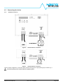
Input connector wiring
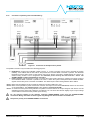
The input mains terminal block accepts wires up to 4mm2 (11AWG). Strip the wire insulation for 8mm, screw tightening torque
0.5…0.6Nm, use only 60/75 Class 1 copper wires.
Warning: before operating on the device disconnect the AC mains and wait at least 1 minute.
4.1.4
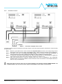
Output connector wiring
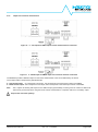
The output terminal block accepts wires up to 35mm2 (2AWG). Strip the wire insulation for 15mm, screw tightening torque
2.5…4.5Nm, use only 60/75 Class 1 copper wires. Refer to Table 1 to define the minimum wire gauge for each model.
Model name
NPS2400C
NPS2400D
NPS2400G
NPS2400R
Rated Vout [VDC]
24
48
72
170
Table 2
Rated Iout [A]
100
50
33
14
Minimum wire gauge [mm2 /AWG]
25 / 3
10 / 7
6/9
2.5 / 13
Recommended output wire gauge
4.1.5
Auxiliary connector wiring
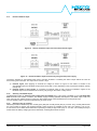
The auxiliary terminal block accepts wires from 0.5mm 2 (20AWG) to 1.5mm2 (15AWG). Strip the wire insulation for 5mm, screw
tightening 0.25Nm, use only 60/75 Class 1 copper wires.
4.1.6
Cooling
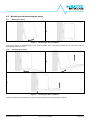
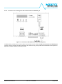
Mount the device in vertical position, keep at least 80mm (3inch) free spacing on upper and lower side, 10mm (0.4inch) free
spacing between adjacent devices. Check periodically that the air inlets in the enclosure are free from dust and other debris that
can obstruct the air flow.
Mount the device in the cooler zone of the cabinet. The thermal protection is activated if the surrounding air temperature is
>50°C (122 °F) along with continuous full load operation. The device restarts automatically after cooling down.
NPS2400 User’s Manual
Rev. 3.0 – 17.02.2015
Page 7/38