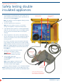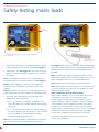
1
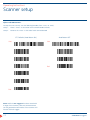
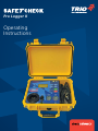
Pro Logger II Operating Instructions About safeTcheck Pro Logger II The safeTcheck Pro Logger II is an electrical Portable Appliance Tester (PAT), designed and manufactured in Australia. It has been designed to comply with Australian Standards AS3100, AS3760 & AS4024.1 to maximise user safety. The Pro Logger II ensures the electrical safety of appliances is compliant with the requirements of the current Australian and New Zealand Standard AS/NZS 3760 (In–service safety inspection and testing of electrical equipment). The The Pro Logger II is unique in that ensures an appliance is correctly connected prior to running a test sequence. Most, if not all other testers, will pass an appliance even if it is not connected in accordance with the standard. With the The Pro Logger II , testing Electrical Safety of Appliances is simple, fast, accurate, thorough and safe. You can test the safety of Class 1 (earthed) appliances, Class 2 (double insulated) appliances, 3 Phase appliances, Fixed and Portable RCD's and extension leads in accordance with the standard, simply and efficiently. There is no interpretation, no ambiguity, just a simple PASS or FAIL. N2068 2 SafeTcheck Pro Logger II Contents 4 Testing of appliances with the Pro Logger II 5 Frequency of electrical safety testing 6 Function and basic technical specification 8 Available options and accessories 9 Preparation of the appliance prior to safety testing 10 Operating the Pro Logger II 11 Safety testing earthed appliances 13 Safety testing double insulated appliances 15 Safety testing mains leads 16 Safety testing other appliances (Other Appliance menu) 18 Run testing (Leakage current test) 19 Run testing earthed (class 1) appliances 20 Run testing double insulated (class 2) appliances 21 Run testing 3 Phase appliances (Option 22 RCD Tester (Option) 24 High current earth test (Option) 25 Battery Power (Option) 26 Utilities Menu (F2 key) 29 Info display (F1 key) 30 Data Logger operating instructions 35 Scanner setup For more information regarding the electrical testing of Portable Electrical Appliances such as Frequently Asked Questions (FAQs), information relating to the standard (AS/NZS 3760), more options for the STC Pro Logger II and for the most recent updates in relation to the Pro Logger II and Portable Appliance Testing go to our SafeTcheck website: www.SafeTcheck.com.au or for all other general Test & Measurement Instrumentation go to our TRIO Test & Measurement website: www.triotest.com.au 3 SafeTcheck Pro Logger II The testing of appliances with the STC Pro Logger II The Pro Logger II will test most 240V 50Hz single phase class 1 and 2 electrical appliances and extension leads to comply with the current electrical safety standard AS/NZS 3760. It will also test, with options fitted, RCDs (both fixed and portable) and 3 Phase appliances. Any appliances with characteristics which may require modified test parameters (in accordance with the standard) may be found in the OTHER APPLIANCE menu. If you experience difficulties or doubts in testing certain appliances please contact TRIO Test & Measurement. TRIO Test & Measurement Sales, Technical & Service Enquiries Phone 1300 852 402 Fax 1300 853 409 [email protected] www.SafeTcheck.com.au General Test & Measurement enquiries Phone 1300 853 407 [email protected] www.triotest.com.au The Pro Logger II has been designed to comply with Australian Standards AS3100, AS3760 & AS4024.1 to maximise user safety. 4 SafeTcheck Pro Logger II Frequency of electrical safety testing (Guide only) The minimum recommended frequency of safety testing of electrical equipment is specified in Australian Standard for in service testing AS/NZS 3760. Type of environment in which equipment is used Earthed appliance Double insulated appliance Extension cords Factories, shops & places of work manufacturing, repair, maintenance or construction 6 months 12 months 6 months Office environment where equipment is not subject to constant flexing of the supply cord 5 years 5 years 12 months Other commercial environments, e.g. 12 months tea rooms, office, kitchens, health care studios, with no protection 12 months 6 months Construction and Demolition sites 3 months 3 months 3 months Hire equipment Before each hire Before each hire Before each hire Note: Some organisations may alter these periods based on a documented risk assessment, undertaken in accordance with the process specified in AS/NZS 4360 (see AS/NZS 3760 for details). 5 SafeTcheck Pro Logger II Function and basic technical specification The Pro Logger II has been designed to comply with Australian Standards AS3100, AS3760 & AS4024.1 to maximise user safety. Mains Power Outlet Check (may be disabled for some situations) The mains power outlet supplying the STC is checked for the existence of an Earth, Active-Neutral transposition and Mains voltage tolerance. Earthed appliances are tested for: • Electrical continuity <=100K Ohm • Earth continuity <=1 Ohm @ 200mA* • Insulation resistance >=1M Ohm (250/500V DC Selectable) Note: If the appliance requires mains power to energise its Off switch (and the switch must be “on” to complete the mains electrical circuit), the Pro Logger II can conduct a Current Leakage Test (Run Test) to ensure Leakage Current is <= 5mA. Double insulated appliances are tested for: (unique to the Pro Logger II) • ensures the stainless steel cloak is correctly in place: • to provide a return path for any leakage current during the insulation resistance test; and • provides user protection from electric shock • Electrical continuity <= 100K Ohm • Insulation resistance >= 1M Ohm (250/500V DC Selectable) Test duration • Approx. 3.0 seconds Electrical stress test parameters • Insulation 500V DC / 250V DC • E arth circuit 200mA nominal (High Current Earth Test Option available)* Run test (leakage current test) • S eparate 20A Run Socket for user safety (no switched earth – compliant with AS3100) • Leakage current clamped at 6mA for user safety. Run Test will terminate at > 6mA leakage current • Earthed Appliance Leakage current <=5mA • Double Insulated Appliance Leakage current <=1mA • Supplies 15A @ 240V AC for the duration of test • The duration of Run Tests is user variable RCD Tester (when fitted) conducts a Lead Test and then an RCD Test • Insulation resistance >= 1M Ohm • Earth circuit continuity <= 1.0 Ohm @ 200mA • E lectrical continuity for resistance Active / Neutral 10K Ohm nominal (< 10K Ohm is considered a short) • Connection polarity (transposition of active and neutral) • Mains Isolation Transformer included • T rip Time < 300mS @ 30mA & < 40mS at 10mA (measured at 0° and 180° crossing) Note: If the appliance requires mains power to energise its On/Off switch (and the switch must be “on” to complete the mains electrical circuit), the Pro Logger II can conduct a Current Leakage Test (Run Test) to ensure Leakage Current is <= 1mA. • S eparate 20 & 32A Run Sockets supplied (other currents available) Extension/Mains leads are tested for: • Checks for appliance running (Switched on) • Insulation resistance >= 1M Ohm • Leakage current <= 5mA • Earth circuit continuity <= 1.0 Ohm @ 200mA* • L eakage current clamped at 6mA for user safety. Run Test will terminate at > 6mA leakage current. 3 Phase Appliance Testing (when fitted) • E lectrical continuity for resistance Active / Neutral 10K Ohm nominal • The duration of 3 Phase Run Test is user variable • 'Figure 8' leads (no earth) Insulation resistance A-N to Cloak >= 1M Ohm Note: *0.2, 10 & 25A test currents are available with the High Current Earth Bond Option 6 SafeTcheck Pro Logger II Function and basic technical specification Display LCD to indicate: •Flush mounted 240V sockets with integrated LEDs to indicate active Test Socket • Pass/Fail Operating instructions • Measured Values (if enabled) • On screen prompts displayed and clearly labeled switches • Possible fault conditions • Step by step instructions detailed in this Manual • User information LEDs to indicate: Warranty period 12 months from date of purchase • Fail / Reset (Red) • Start / Ready (Green) • Which test socket to use (For Insulation and Run Test sockets) Data Logging • Complete user control of Data Logging functions: – Logging can be switched on/off – Individual Fields can be switched on/off • Uses Keyboard and/or Scanner • Actual Time & Date stored with each test record • Stores 500 or 2000 records • R ecords are easily uploaded to a PC (from the Pro Logger II's memory or in real time via 'Data Dump' to the USB port) • R ecords are always appended to memory to prevent accidental loss of data (no over writing of stored data) Power requirements 240V AC +/– 10% @ 50Hz Battery option for portable operation available – see section Battery Power (Option) Lifetime warranty Check online at www.SafeTcheck.com.au for a lifetime warranty (Cradle to Grave care) Calibration period Recommended every 12 months (24 months periods also available with verification every 12 months – contact TRIO for details) Repairs and calibration (Cradle to Grave care) SafeTcheck PATs can only be calibrated by TRIO Test & Measurement Service Centres. We recommend that the Pro Logger II is returned to a TRIO Test & Measurement Service Centre for repair and/ or calibration. In doing so you are assured that any recent enhancements to the Hardware & Firmware (where applicable to your Pro Logger II) will be included in the repair or calibration as a matter of policy Contact TRIO Test & Measurement or go to www.SafeTcheck.com.au for details The mains power outlet supplying the Pro Logger II is checked for (Mains Power Outlet Check): Included Accessories •The existence of an Earth •Active–Neutral transposition; and • C ombined return test lead and clip for both Class I & II appliances •Mains Voltage tolerance • Calibration Certificate • STC DownLoader CD including Manuals Test inlets •Flush mounted mains plugs for test purposes (both IEC and standard 240V), protected from accidental application of 240V 50Hz mains voltage 7 Note 1: Tolerance on all stated values is ±5% Note 2: TRIO Test & Measurement reserves the right to change specifications at any time without notice. SafeTcheck Pro Logger II Available options and accessories We have developed a range of accessories to complement the Pro Logger II • R CD Tester (10mA & 30mA Portable & Fixed RCDs c/w integrated Isolation Transformer) • High Current Earth Tester (200mA continuity, 10A routine and 25A type tests) • 3 Phase Appliance Tester (20 & 32A Sockets) • B attery power Option (battery power for more than one day's testing) • Stainless steel cloak (350 x 600mm) • Large stainless steel cloak (350 x 900mm) • Figure 8 & Clover Leaf to IEC Mains adaptors • Scanner • Keyboard • Upgrade from 500 to 2000 stored records • Data & Asset Management Software • USB Tag Printer for connection to Management Software • Test tags (with optional company logos & barcodes) • Barcoded item stickers, tested labels and danger tags • Removable lid • Collapsible Trolley Trio Test & Measurement Ph: 1300 852 402 Web: www.SafeTcheck.com.au 8 SafeTcheck Pro Logger II Operating Instructions Preparation of the appliance prior to safety testing General visual inspection Preparation of an earthed appliance to be safety tested 1Ensure the appliance to be safety tested has no obvious mechanical faults and is free from external damage. 1Switch any/all switches ‘ON’. 2Inspect the mains lead for any damage, defects or loose terminals in the accessories, connectors, plugs or outlet sockets. Common faults encountered: a) Frayed, cracked or otherwise damaged mains lead. b)Exposed conductors and/or covered by insulation tape. 2Set any speed control or thermostat to ‘FULL ON’ (Maximum speed). 3Preparation for earthed appliance to be safety tested is now complete and may be connected to the Pro Logger II. (see Safety Testing Earthed Appliances) c) Abrasions in the outside insulation jacket. Preparation of a double insulated appliance to be safety tested d) Mains lead anchorage at plug or appliance entry. 1Switch any/all switches ‘ON’. 3Check that any controls, alarms and replaceable protective devices accessible to the user, are of correct rating and in good working order. 2Set any speed control or thermostat to ‘FULL ON’ (Maximum speed). 4 Inspect all switches and speed controls for mechanical operation; ensure switches and controls are clear of any obstruction, e.g. filings, swarf, metal particles, grease, etc. 5Confirm all identity tags/labels etc. pertaining to the frequency of safety testing are correctly attached and records of all test/inspections are kept to ensure the safety integrity and history of the appliance. 3Preparation for a double insulated appliance to be safety tested requires the appliance to be wrapped in a stainless steel cloak taking care to make contact with all metal components and the exterior of the appliance where hand contact is normally possible. 4The double insulated appliance is now ready to be safety tested and may be connected to the Pro Logger II. (see Safety Testing Double Insulated Appliances) 6 Unroll extension leads/rolls and inspect as above. Identify the appliance to be tested Examine the appliance to be tested and identify whether the appliance is an earthed appliance, a double insulated appliance or an extension cord. Earthed appliances should always have an earth pin on their plug, and will normally have exposed metal components. Double insulated appliances may be identified by the double symbol, and/or by the absence of an earth pin on insulation a moulded socket (not deliberately removed or broken off). ote: The above description regarding the inspection and N testing of electrical appliances is a guide only. Please refer also to the current standard AS/NZS 3760. WARNING Upon completion of a safety test and subsequent removal of test lead and/or stainless steel cloak, please ensure all switches, speed or thermostat controls are returned to their ‘OFF’ or minimum position. Note 1: Many double insulated tools are colour coded blue. ote 2: If any doubt exists about the Class of an appliance N (Class I or II), the appliance should be tested as an earthed appliance first (see also OTHER APPLIANCE menu). 9 SafeTcheck Pro Logger II Operating Instructions Operating the STC Pro Logger II Lcd display Function keys (f1 & F2) INFO DISPLAY (F1) Utilities Menu (F2) Appliance selection keys Computer I/F (USB Port) *Keyboard & Scanner (USB Port) Mains power socket (IEC) Start test reset Accessory Well Standard IEC Test Plug Standard 240v test plug Utility Socket (3 Phase Option) Cloak & Earth Return socket Insulation test socket Place the Pro Logger II on a convenient non–conductive working surface. Insert the mains plug into a correctly wired and earthed mains power outlet. The following sequence will occur: 1Start Prompt appears on the Liquid Crystal Display (LCD); (If the Data Logging function is turned on then the Time and Date and Memory used is displayed. Pressing reset after each of these screens will display the Start Prompt); 2 There is a short beep; and 3 The TEST and FAIL LEDs flash momentarily. The Pro Logger II is now ready to perform Appliance Safety Testing. Any departure from these conditions may mean the Pro Logger II has a fault and should be returned to a TRIO Test & Measurement Service Centre for service. 10 Leakage test socket (run test) note: a Test Socket's LED will flash to indicate which socket is active Note 1: If a message appears on the LCD indicating an Active–Neutral reversal or an Earth fault then there is a problem with the power outlet supplying the Pro Logger II. At this point the tester will cease to function, preventing any appliance testing being performed under fault conditions. Either the power outlet fault must be corrected prior to proceeding or an alternate power outlet must be used to power the Pro Logger II. *Note 2: In some earlier models with dual USB ports, when using the Scanner together with the Keyboard, connect the Keyboard to the Scanner’s “Keyboard Wedge Cable” via the PS/2 connection. Connecting the keyboard and scanner via separate USB ports will occasionally cause the keyboard to send spurious characters to the Pro Logger II while scanning barcodes. SafeTcheck Pro Logger II Operating Instructions Safety testing earthed appliances 1Ensure the Pro Logger II is in the self test mode i.e. Start Prompt appears on the LCD. 2Plug the appliance to be tested into the socket labelled INSULATION RESISTANCE provided on the front panel of the Pro Logger II. The appliance should be connected directly and not via an extension lead. ote 1: A FAIL indicating “poor continuity” denotes lack of a N circuit path between the Active and Neutral of the appliance. If the appliance switch is on and this error occurs then go to the RUN TEST. WARNING 3Connect the Return Lead to the unit via the Earth Return Socket To avoid uncertain results when testing an earthed appliance, ensure that: 4Connect the Return Lead to a convenient metal (conductive) point of the appliance under test. 1The earth clip is securely attached to the metal frame. If any earthed appliance has one or more metal components which are possibly not connected together, the overall test must be repeated with the Return Lead connected to each metal component in turn. 2The appliance under test has been disconnected from all other equipment. 5Switch the appliance to be tested ‘ON’ Note: Any or all switches must be "on" to ensure testing of the appliance's complete electrical circuit. 6If the appliance to be tested has a variable speed or thermostat control fitted, turn the control to its highest setting, this will connect Active/Neutral direct to the internal windings. 3The test is conducted on an insulated or (non metallic) benchtop. Note 2: For a FAILED earthed appliance known to be fitted with surge protection i.e. metal oxide varistors (MOVs), test again using Class 2 (250V) test, see OTHER APPLIANCES. Note 3: For appliances with no class identification, no accessible earth and having 3 pins on the plug, a standard earthed appliance test may fail, see other appliance menu. 7Select EARTHED APPLIANCE. The Pro Logger II is now ready to test the appliance. Evaluation of in–service testing results for earthed appliances Note: If Data Logging is switched on then additional information will be requested. See section entitled ”Data Logging” Where the Pro Logger II identifies an appliance which fails to comply with the test criteria, the equipment shall be: The green indicator alongside "Start" will now be flashing. 1Withdrawn from service immediately and have a label attached to it warning against further use. Note: During the test cycle the user may apply stress to the supply lead and plug in order to detect any intermittent faults 2Repaired by the appropriately qualified person and retested after repair. 8Test results will be displayed on the LCD along with audible tones and flashing LEDs. C a)Pass – 'Thumbs Up' and PASS indication on LCD and a short BEEP with a GREEN indicator flashing along side "Start". C 'Thumbs Down' and/or LCD Prompt indicating b) Fail – the most probable reason for failure with: The measured value (if enabled), a continuous BEEP and a RED indicator flashing alongside "Reset". 11 3Refit test identity tags/labels etc. and log test in safety history records. WARNING Upon completion of a safety test and subsequent removal of test lead and/or stainless steel cloak, please ensure all switches, speed or thermostat controls are returned to their ‘OFF’ or minimum position. SafeTcheck Pro Logger II Operating Instructions Safety testing earthed appliances Select Earthed Appliance test Cloak & Earth Return socket RETURN LEAD AND Clamp (Class I & II) Switch appliance ON and set thermostat or speed control to maximum 12 SafeTcheck Pro Logger II Operating Instructions Safety testing double insulated appliances 1Plug the double insulated appliance to be tested into the socket labelled INSULATION RESISTANCE provided on the front panel of the Pro Logger II. Cloak & Earth Return socket SELECT DOUBLE INSULATED APPLIANCE TEST Note: The appliance must be plugged in directly, and not via extension leads. 2Switch the appliance to be tested ‘ON Note: Any or all switches must be "on" to ensure testing of the appliance's complete electrical circuit. 3If the appliance to be tested has a variable speed control fitted, turn the control fully ‘ON’ or to the highest speed, this will connect Active/Neutral direct to the internal windings. 4Wrap the appliance in the stainless steel cloak, taking care to make contact with all metal components and the exterior of the appliance where human hand contact is normally possible. The stainless steel cloak may also be woven metal cloth mesh, conductive braid, aluminium foil, or other suitable flexible conductor with low resistance (less than 100 Ohms). Note: The wrapped appliance should be on an insulated bench to avoid earthing the measurement circuit in the Pro Logger II. 5Connect the Clamp of the Return Lead to the stainless steel cloak as shown. ensures the Clamp is connected to the stainless steel cloak. RETURN LEAD AND Clamp 6Select Double Insulated. The Pro Logger II is now ready to test the appliance. Note: If Data Logging is switched on then additional information will be requested. See section entitled ”Data Logging” The green indicator alongside "Start" will now be flashing. Note: During the test cycle the user may apply stress to the supply lead and plug in order to detect any intermittent faults stainless steel cloak Switch appliance on and Set appliance thermostat or speed control to maximum 13 SafeTcheck Pro Logger II Operating Instructions Safety testing double insulated appliances (continued) 7During the test cycle the Pro Logger II's will check that the stainless steel cloak and return lead are correctly connected. This will ensure that the correct test environment is present to measure the insulation resistance of a double insulated appliance. is a unique feature of the SafeTcheck Portable Appliance Testers. 8If the verification test passes the Pro Logger II will continue with the double insulated appliance test. If the verification test fails then it maybe for one or more of the following reasons: a) has found the double insulated appliance is not correctly wrapped or connected to the return lead for double insulated appliances. Note 1: A FAIL indicating “poor continuity” denotes lack of a circuit path between the Active and Neutral of the appliance. If the appliance switch is on and this error occurs then go to the RUN TEST. Also see STC Pro Logger II Manual – Updates for more on Bypassing the error. ote 2: For a FAILED double insulated appliance known to be N fitted with surge protection i.e. metal oxide varistors (MOVs), test again using Class 2 (250V) test, see OTHER APPLIANCE menu. Note 3: For appliances with no class identification, no accessible earth and having 3 pins on the plug, a standard double insulated test may fail, see other appliance menu. Note 4: If for some reason it is not practical to use the stainless steel cloak, then a 'Probe Mode' may be used. This Is not recommended as a test may proceed without a return lead connected. This will ensure a 'Pass" for the test but a valid test will not have been performed. To bypass checkConnect, switch to 'Probe Mode', see OTHER APPLIANCE menu. b) The assumed double insulated appliance is in fact an earthed appliance. c)The double insulated appliance is connected to the Pro Logger II via a non–compliant extension cord. d)The appliance is earthed via another path such as a metal earthed bench. Evaluation of in–service testing results e) Both active (A) and neutral (N) leads are open circuited in the appliance e.g. failure to turn ‘ON’ appliance switch(es). Where the Pro Logger II identifies an appliance/tool which fails to comply with the test criteria the equipment shall be: f) The resistance of the stainless steel cloak around the appliance is too high. 1Withdrawn from service immediately and have a label attached to it warning against further use. g) T he appliance has low capacitive coupling between the external surface (the stainless steel cloak) and the internal electrical circuit. Place some of the mains cable under the Cloak to overcome this problem. This may apply to some appliances with minimum internal circuitry e.g. a plastic bedlamp, a vacuum cleaner where the motor is separated by a relatively large distance from the case, or a mobile phone charger. 2Repaired by the appropriately qualified person and retested after repair. 9 Test results will be displayed on the LCD along with audible tones and flashing LEDs. C a)Pass – 'Thumbs Up' and PASS indication on LCD and a short BEEP with a GREEN indicator flashing along side "Start". b) Fail – 'Thumbs Down' and/or LCD Prompt indicating the most probable reason for failure with: The measured value (if enabled), a continuous BEEP and a RED indicator flashing along side "Reset". 3Refit test identity tags/labels etc. and log test in Safety History records. WARNING Upon completion of a safety test and subsequent removal of test lead and/or stainless steel cloak, please ensure all switches, speed or thermostat controls are returned to their ‘OFF’ or minimum position. C may be turned off by switching to NOTE: Probe Mode. See the UTILITIES MENU. 14 SafeTcheck Pro Logger II Operating Instructions Safety testing mains leads SELECT LEADS TEST Lead under test EPOD under test 1 Plug the extension lead into the plug and socket labelled LEADS provided on the front panel of the Pro Logger II. 2Select LEADS. The Pro Logger II is now ready to test the appliance. The green indicator alongside "Start" will now be flashing. ote 1: The appliance should be on an insulated bench to N avoid earthing the measurement circuit in the Pro Logger II. ote 2: If Data Logging is switched on then additional N information will be requested. See section entitled ”Data Logging” ote 3: During the test cycle the user may apply stress to the N supply lead and plug in order to detect any intermittent faults 3 Test results will be displayed on the LCD along with audible tones and flashing LEDs. C 'Thumbs Up' and PASS indication on LCD a)Pass – and a short BEEP with a GREEN indicator flashing along side "Start". 'Thumbs Down' and/or LCD Prompt indicating b) Fail – the most probable reason for failure with: The measured value (if enabled), a continuous BEEP and a RED indicator flashing along side "Reset". C ote 1: If the extension lead has a fixed socket (as in extension N reels), this must be connected to the fixed test plug on the 15 Pro Logger II with a short TEST extension lead of rated voltage and current, which has been previously tested and verified SAFE. Normally, extension leads must be tested individually and not cascaded. Note 2: If EPODs are fitted with surge protection i.e. metal oxide varistors (MOVs), they may fail the LEADS test. If so, test again using EPOD (250V) test, see OTHER APPLIANCES. Note 3: Each socket of the EPOD must be tested in turn. Note 4: Long extension lead may fail if it is left coiled. Be sure to uncoil leads prior to testing. This must be done to visually inspect the lead in any case. Note 5: Additional Two (2) Wire Lead Test Many modern appliances use a two wire mains power lead with a figure 8 style socket i.e. no earth conductor. The Pro Logger’s Lead Test tests this style lead as a Class 2 appliance (requires a Figure 8 adaptor; a Clover Leaf adaptor is also available). The Pro Logger will conduct an Insulation Resistance (IR) Test if the lead is found to have no earth by design (requires confirmation by the user). The IR is measured between the inner mains conductors and the Pro Logger’s Cloak which is wrapped around the length of the lead. This feature is available on all testers with Firmware Version V4.64 and above SafeTcheck Pro Logger II Operating Instructions Safety testing other appliances (OTHER APPLIANCE menu) Select Other Appliance The Pro Logger II is capable of testing many electrical appliances with unusual characteristics. The Other Appliance menu is used to select the test suitable for any of these appliances. The user may scroll though the list by using the F1 and F2 keys. 1Appliances such as those fitted with surge protection or MOVs (Metal Oxide Varistors) may be tested at 250V (instead of 500V) by selecting one of the following: •Class 1 250V •Class 2 250V 2Appliances requiring the mains voltage to be applied to activate the On/Off switch, shall have their leakage current checked by selecting one of the following: •Class 1 Run Test •Class 2 Run Test 4Appliances employing Mineral Insulated Metal Sheath (MIMS) such as stoves and electric jugs may be tested using a run test by selecting: •MIMS Run Test 5 A s for appliances in 1 above EPODs with surge protection may be tested at 250V by selecting: • EPOD 250V 6RCDs rated at 10mA, 30mA either portable or fixed may be tested by selecting one of the following*: •10mA Portable RCD •30mA Portable RCD •10mA Fixed RCD •30mA Fixed RCD (see also Run testing) 7Appliances employing a PIEZO starter such as the starter on a portable gas stove may be tested by performing a: 3An earth continuity test may be conducted by selecting: •PIEZO Run Test •Earth only test 16 SafeTcheck Pro Logger II Operating Instructions Safety testing other appliances (OTHER APPLIANCE menu) 8Appliances connected to the mains via a 3 pin plug with no Double Insulated (Class 2) symbol visible, should be considered Earthed Appliances (Class 1), however, with some appliances of this kind, the earth conductor provides not only a degree of electrical safety but also a path to conduct EMI currents, to reduce noise. This EMI current may cause an appliance to fail due to, what the Pro Logger sees, as excessive leakage. Also, with some other appliances, there is simply no practical way of finding a connection to the Earth Conductor i.e. it has no exposed earthed metal parts. The first phase of this test, while running the appliance, looks for 1mA of leakage current between the Pro Logger’s Cloak and the appliance’s case i.e. a standard Double Insulated Run Test. If the Pro Logger measures more than this, it will try again with an increased 5mA threshold (because the appliance is Earthed, up to 5mA of Leakage Current is permissible). 9Where a Class I earthed appliance requires a longer than normal run time (approximately 2 minutes), the following test may be used: •Long Class I Run† 10.For a 3 phase appliance Run Test, select*: • 3 Phase Run Test Note 1: New tests may be added to the Other Appliance menu from time–to–time. For details regarding upgrades contact TRIO. *Note 2: The RCD Tester and 3 Phase Run Test are options for the Pro Logger II (see also RCD Tester & Run testing 3 Phase appliances) †Note 3: Available only in Pro Logger II's with firmware version 4.04 or later. . The person conducting the test will be warned that the 1mA threshold has been exceeded and that a 5mA test will be conducted. Any more than 5mA of leakage current will cause the test to fail. To test these appliances use: • Three (3) Pin Class 2 Run Test WARNING This test does not look for the presence of an Earth Conductor. It should only be used if the normal Earthed Appliance Insulation Resistance Test continually has failed. 17 SafeTcheck Pro Logger II Operating Instructions Run testing (Leakage current tests) TRIO Test & Measurement recommends that the following Run tests are used only if the Insulation testing of an appliance fails or is unsuitable for that type of appliance. Run tests apply the mains voltage (240V) to the appliance under test, exposing the user to the risk of personal injury (eg Electric Shock). Remember, until proven otherwise the appliance under test should be thought of as being unsafe for use. Overview The Run Test is primarily for performing safety tests on appliances that require a mains voltage applied to operate their mains switch (on/off switch). 18 SafeTcheck Pro Logger II Operating Instructions Run testing earthed (class 1) appliances 1Ensure the appliance is switched off. 2Plug the appliance into the separate Run Test socket. 3Connect the return lead to the Pro Logger II via the Earth Return Socket. 4Connect the Clamp of the Return Lead to a convenient earthed metal point on the appliance under test. WARNING The appliance will operate for up to 20 seconds in the run test mode. Ensure rotating parts are NOT wrapped in the cloak. Appliances such as drills, angle grinders etc should be firmly restrained during the run test. 5Switch the appliance on. 6Select Class 1 Run Test under Other APPLIANCE menu (F1 and F2 keys move the selection of mode up or down respectively) 7Press START button and follow the screen instructions. The appliance will operate for up to 20 seconds during the run test. 8For Class I appliances requiring a longer than normal run test duration, move to Long Class I Run under OTHER APPLIANCE menu. Switch appliance on’ & ‘Set appliance thermostat or speed control to maximum’ Note 1: Pressing RESET at any point during the Run Test will shorten the test duration. This does not invalidate the test result. Note 2: If Data Logging is switched on then additional information will be requested. See section entitled ”Data Logging” WARNING Upon completion of a safety test and subsequent removal of test lead, please ensure all switches, speed or thermostat controls are returned to their ‘OFF’ or minimum position. 19 SafeTcheck Pro Logger II Operating Instructions Run testing double insulated (class 2) appliances 1 Ensure the appliance is switched off. 2Wrap the appliance in the stainless steel cloak (please see Note 2 below) 3Plug the appliance into the separate Run Test socket. 4Connect the return lead to the Pro Logger II via the Earth Return Socket and connect the return lead clip to the stainless steel cloak as per diagram. WARNING The appliance will operate for up to 20 seconds in the run test mode. Ensure rotating parts are NOT wrapped in the cloak. Appliances such as drills, angle grinders etc should be firmly restrained during the run test. 5Switch the appliance on. (The appliance may need to be switched on prior to being wrapped in the cloak) 6Select Class 2 Run Test under Other APPLIANCE menu using the F1 and F2 keys. ress START button and follow the screen 7 P instructions. The appliance will operate for up to 20 seconds during the run test. Note 1: Pressing RESET at any point during the test will shorten the test duration. This does not invalidate the test result. to test for Note 2: The tester does not use the presence of a return lead and/or cloak in the Run Test mode. Failing to use the return lead and/or cloak invalidates the test. Do not wrap moving parts and be aware of appliances with hot surfaces Switch appliance on & Set appliance thermostat or speed control to maximum Note 3: If Data Logging is switched on then additional information will be requested. See section entitled ”Data Logging” WARNING Upon completion of a safety test and subsequent removal of test lead, please ensure all switches, speed or thermostat controls are returned to their ‘OFF’ or minimum position. 20 SafeTcheck Pro Logger II Operating Instructions Run testing 3 Phase appliances (Option) Overview The 3 Phase Run Test (where fitted) tests Portable 3 Phase Appliances in accordance with AS/NZS 3760. This option is available with 20 and/or 32A 3 phase sockets or other current ratings as requested. The test looks for an Earth Connection <= 1 Ohm; a run current to ensure the appliance is switched on and running; and a leakage current of <= 5mA. The test is a Long Run Test. It may be shortened at any time after the test commences by pressing “Reset” twice in quick succession. If any of the test parameters (Earth Current, Run Current or Leakage Current) fail, then the 3 phase test fails otherwise the Pro Logger will indicate a pass. Connection interface cable for 3 Phase Appliance Operation This test requires 2 connections to the Pro Logger: an earth return connection to the Device Under Test’s (DUT) chassis; and a connection the 20 or 32A 3 phase socket adaptor (this is a ‘din’ type socket in the well of the Pro Logger II). The 3 phase socket adaptor is plugged into a 3 phase power source, then the DUT into the 3 phase adaptor. The DUT should be running to conduct a test. To test a 3 phase extension lead, run a test with the extension lead connected between an already tested (and known electrically safe) 3 phase appliance and the 3 phase adaptor. Select the appropriate 3 Phase Run Test option from the OTHER APPLIANCE menu; use the F1 and F2 keys to scroll up and down the list of options. 3 Phase Run Test Connect to Utility Socket Connect to 3 Phase supply Earth Return Lead 3 phase supply for the Device Under Test 21 SafeTcheck Pro Logger II Operating Instructions RCD Tester (Option) Known good extension lead Portable RCD under test Portable RCD Lead Figure 1 Figure 2 Overview This test can be used regardless of the latching characteristics of the RCD being either electronic or mechanical (as indicated by Fig 1 & 2). When fitted to the Pro Logger II the RCD tester ensures 10mA, 30mA, portable or fixed RCDs comply with the Australian standard for Electrical Appliance Safety (AS/NZS 3760). When testing portable RCDs the Pro Logger II inserts an isolation transformer into the circuit to ensure any fixed RCD (in the mains supply circuit) is not tripped. The Pro Logger II now incorporates a single In–Line RCD lead test that ensures that the appliance is tested to comply with the standard as both an extension lead and RCD. 22 When testing fixed RCDs the Pro Logger II uses a battery power until the RCD is reset and mains power is restored. In earlier models the Pro Logger II's battery will power the LCD only. This ensures the displayed test result is visible to the user for approximately 2 minutes after the mains power is tripped during testing. SafeTcheck Pro Logger II Operating Instructions RCD Tester (Option) Operation Select the appropriate RCD test option from the Other Appliance menu; use the F1 and F2 keys to scroll up and down the list of options. Portable RCDs (10 or 30mA) Start the selected portable RCD test by pressing the “Start” button. A message on the LCD display will then instruct you to: 1Connect the portable RCD between the “Standard 240V Test Plug” and “Leakage Test Socket” on the front panel of the STC. 2Press "Start" to initiate the test. The Pro Logger II will then perform an "Electrical Test" (Polarity, Insulation & Earth). 3The Pro Logger II will then display "Arm RCD then hit Start". At this point, arm the RCD and press "Start" to perform the RCD trip time test. 4 After the RCD trips, the trip time will be displayed in milliseconds together with a “Pass” or “Fail” message. To ensure the RCD has been tested on both raising and falling edges of the mains cycle, the Pro Logger II will then prompt you to perform a 180° test by resetting the RCD and pressing “Start” (this test is optional). After the RCD trips, the trip time will be displayed in milliseconds together with a “Pass” or “Fail” message. Note: Pressing "Reset" after each RCD time test will move you quickly to the next screen. Fixed RCDs (10 or 30mA) The Pro Logger II will then prompt you to perform a 180° test by resetting the RCD and then pressing “Start” (this is an optional test, ensuring the RCD has been tested on both raising and falling edges of the mains cycle). After the RCD trips, the trip time will be displayed in milliseconds together with a “Pass” or “Fail” message. In earlier models the screen will be active for 2 minutes to enable you to record the time. WARNING 1When the Pro Logger II is in the RCD test mode, 240VAC is present on the front panel Test Socket 2Do not connect an appliance to a Portable RCD under test 3When testing a Portable RCD do not use the front panel “IEC 240V Test Plug”. Only use the “Standard 240V Test Plug” 4Care should be taken when tripping any Fixed RCD (causing a sudden loss of mains power) that other equipment, reliant on power from that circuit, will not be damaged. Note 1: RCD Trip Time Threshold (Portable 30mA RCD Test function) When testing Portable RCDs the trip current is suddenly applied and the trip time measured. In the case of 30mA Portable RCDs the acceptable trip time is ≤300mS however at 150mS (a threshold considered good practice AS37060:2010) the Pro Logger will fail the RCD in Firmware below Firmware Version V4.46; for V4.46 and above the Pro Logger will provide the user with a warning (not a fail) if the Trip Time is ≥150mS but ≤300mS. A Fixed RCD refers to an RCD in the mains power circuit supplying the Pro Logger II. Note 2: In some cases a previously tested and safe extension lead may be required to connect the Standard 240V Test Plug and the female socket of the RCD under test. Start the selected Fixed RCD test by pressing the “Start” button. A warning will be displayed stating “Power will fail during this test”. Note 3: If Data Logging is switched on then additional information will be requested. See section entitled ”Data Logging” Press the “Start” button again to initiate the test. After the RCD trips, the trip time will be displayed in milliseconds together with a “Pass” or “Fail” message. The Pro Logger II will provide power to the display while the RCD is reset and mains power is returned. 23 SafeTcheck Pro Logger II Operating Instructions High current earth test (Option) Overview 3 Type Test (25A) When fitted, the High Current Earth Test Option enables the user of the Pro Logger II to apply any one of 3 test currents when testing earth circuits. The option consists of a fully integrated programmable constant current switch mode power supply capable of delivering up to 25A into the earth circuit of an electrical appliance under test. Same test as applied to selected sample electrical appliances during the manufacturing process. For manufacturers the Type Test is mandatory (conducted in accordance with AS/NZS 3100). The earth resistance threshold, for this current only, is set to 0.2Ω. The selected current will be displayed on the LCD during testing. This current may be set as a default for all tests or for the current test only. Note 1: The Type Test earth resistance threshold for AS/NZS 3100 is 0.1Ω. The threshold in the Pro Logger II is 0.2Ω. A threshold of 1Ω at 25A is not possible due to the 12V maximum voltage set for this test; as stated in AS/NZS 3760. Due to this low resistance threshold, the Type Test (25A) may not be suitable for extension leads. Operation To access the menus relating to the High Current Earth Tests select F2 when the Start Prompt is displayed on the Display. After pressing F2, scroll down the list of options (using the F1 and F2 keys) until the desired current range is displayed. The selected current setting may then be set to one of 2 modes: 1Press Start for a “temporary setting” test where the selected test current is set until the Pro Logger II is switched off. After the power is switched on again the test current will have reverted to 200mA; or Note 2: For STCs with serial nos. 10010, 10216, 10217, 10218, 10219 &10225 only the 200mA continuity test is conducted when performing a Leakage Current Test (Run Test) on an appliance. If that appliance also requires a high current earth test then the “Earth test only” should be used in conjunction with the run test. 2Press F2 for the selected test current to be set as the default test current for all future Earth Tests. 3If an earth test is conducted then the selected current will displayed on the display prior to the test commencing. Description of test settings 1 Continuity Test (200mA) This is the default general purpose setting, suitable for all appliances including Electronic and IT. The earth resistance threshold is set to 1Ω. 2 Routine Test (10A) Same test as applied to all electrical appliances during the manufacturing process. For manufacturers, the Routine Test is mandatory (conducted in accordance with AS/NZS 3100 ). The earth resistance threshold is set to 1Ω. 24 SafeTcheck Pro Logger II Operating Instructions Battery Power (Option) Overview NOTE: When fitted, the Battery Power Option will power the Pro Logger II for far in excess of 360 Tests (more than one day's testing). This option will remove the need for mains power and makes the Pro Logger II truly portable. 1.While charging, do not select any tests, this will disable the battery charge mode (if this occurs, remove the mains power and restart the Battery Charge Mode sequence). Users of the Battery Power Option should note: 2.The battery will not charge while the Pro Logger is in Test mode 1.Insulation and earth testing only are available in Battery mode 3.A low battery condition will display a screen message “Low battery reconnect to mains” 2.To enter Battery mode press “Start” until the Pro Logger beeps (battery symbol in the bottom left corner of display will appear in this mode) 4.Storing the Pro Logger with a flat or partially charged battery will decrease the life of the battery 3.In Battery mode the Pro Logger will automatically shut down after 3 minutes, if no key is pressed 5.Recharge at least every 6 months, more often if possible 4.The Pro Logger may be switched from battery to mains without losing power (the battery will not charge in this mode – see Battery Charge Mode) 5.Failing to follow these instructions will reduce battery life and void the battery’s warranty Operation For a new Pro Logger – ensure the battery is initially fully charged: 1.Power the Pro Logger from mains power 2.Set the Pro Logger into Charge mode (see below) 3.Wait for “Charge Complete” prompt to appear and then press “Start” 4.Turn the Pro Logger off by disconnecting the mains power Battery Charge Mode (following these steps will extend the life of the battery): 1.Power the Pro Logger from mains power (If already on, switch off and back on again) 2.The prompt “select test” needs to be displayed (If in database mode, press reset unil “select test” is displayed). The Battery will now be charging 3.Wait for the “Charge complete” prompt to appear 4.Press “Start” to acknowledge the charged condition 5.When fully charged the Pro Logger may be stored or it is ready for appliance testing 25 SafeTcheck Pro Logger II Operating Instructions Utilities Menu (F2 key) Overview All Data Logging Utilities, display adjustment, measured values, earth current options (when fitted) and the setting of time & date are available from this menu. The Utilities Menu is accessed via the F2 key when the Pro Logger II is at the Start Prompt. Once in the menu, the user may scroll though the list by using the F1 and F2 keys. To select an option, use the scroll keys. Once highlighted, press "Start" to enable the option or "Reset" to disable. A will appear at the right of an enabled option. Menu Options: Upload test results (See Data Logging). Delete test results (See Data Logging). Enable database (See Data Logging). Ask for Venue (See Data Logging). Ask for Technician (See Data Logging). Ask for App# (See Data Logging). Ask for Visual P/F (See Data Logging). Ask for Tag# (See Data Logging). Ask for Comment (See Data Logging). Earth continuity 0.2A (When High Current Earth Test option is fitted) The Earth Continuity Current maybe set to either 0.2A as a default or as a 'one off'. Routine test 10A (When High Current Earth Test option is fitted) The Earth Continuity Current maybe set to either 10A as a default or as a 'one off'. Type test 25A (When High Current Earth Test option is fitted) The Earth Continuity Current maybe set to either 25A as a default or as a 'one off'. Measured values If enabled, Measured values will be displayed for failed tests. Adjust display Adjust the contrast of the LCD display. Set Time/Date (See Data Logging). Switch between Fail on poor cont. Fail on poor continuity – if set to 'off', will allow the operator to bypass the check for a closed mains switch (it is recommended that this is always set to 'on'). Printer Enable 26 and Probe Mode. Not yet implemented SafeTcheck Pro Logger II Operating Instructions Utilities Menu (F2 key) Where it is not practical to use the stainless steel cloak to Test Double Insulated Appliances, the following may be used: • Probe Test The SafeTcheck Pro Logger II has this Probe Test mode, available on all testers with Firmware Version V4.46 and above. By default Pro Loggers use the unique feature in conjunction with a Stainless Steel Cloak to perform an Insulation Resistance (IR) test on Double Insulated 27 Appliances. ensures the Device Under Test (DUT) is both correctly connected to the Pro Logger (to provide a return path for leakage currents) and its exposed surfaces adequately covered to reduce the chance of an erroneous test result. feature is disabled. During a Probe Test the This gives the operator the ability to use the probe, the cloak or a combination of both to test Double Insulated Appliances. The test also provides adequate time to move the probe to several points on the DUT’s surface before the test is complete. SafeTcheck Pro Logger II Operating Instructions Utilities Menu (F2 key) WARNING: Unlike CheckConnect the Probe Test does not look for a completed return circuit. A test conducted without a return circuit is an invalid test; unfortunately the Pro Logger II will still indicate a PASS test result even if the probe is not connected to the appliance under test! In some cases the operator may find that the Probe Test is more appropriate or convenient e.g. the size or physical location of the DUT may make it difficult to use the cloak or . To switch between the Double Insulated Probe Test and Options, go to the Utilities Menu under the F2 Key, Scroll down to the Option using the F2 Key and then select the required option. The selected option will always have a small rectangle to its right. NOTE: TRIO Test & Measurement recommends the use of for most, if not all, IR tests on Double Insulated appliances. Failure to use this option with an incorrectly connected appliance may mean the test result is incorrect. This potentially dangerous situation exists with any Portable Appliance Tester without (please refer to the Warning above). Correct use of the Cloak and is recommended to protect the operator from electric shock. This feature complies with the mandatory Safety Standard AS4024.1 SAFETY OF MACHINERY DESIGN AND OPERATION. While performing Insulation Resistance (IR) tests on Double Insulated or Earthed Appliances, it may be difficult, or even impossible, to complete the test because of a reported “Continuity Failure”. This may be a result of the appliance’s Mains or On/Off Switch not being closed; or the Pro Logger interpreting a closed switch with high impedance, as “not closed”. In these cases use the user option to bypass a Failed Continuity: • Fail on poor cont (Firmware V5.20 and above & Hardware V8.0 only) If the Pro Logger reports a Continuity Failure, the Pro Logger presents the user with an option to bypass the error and proceed to the IR test. A user should only proceed if the following is true: 1.the user is satisfied that the appliance’s mains switch is closed; and 2.the mains switch doesn’t require mains power to be activated. This may be occur when testing Phone Battery chargers such as those for iPhones. NOTE: This user option is not available on Firmware Version V4.67 to V5.09 & Hardware V7.0 NOTE: If in doubt, do not bypass the Continuity Failure error. Always err on the side of caution and consider the test a failure. 28 SafeTcheck Pro Logger II Operating Instructions Info display (F1 key) Overview The info display will provide the user with information relating to the Pro Logger II itself in relation to its Firmware, hardware, Date & Time, and Data Logging memory & records used. Operation At the 'Select Screen' pressing F1 will step though the following information: • The version number contains the Firmware and Hardware revisions associated with the Pro Logger • Message regarding the 'Results Dump' indicates that the tester will send test data to the communications port after each test. This facility is not present in some earlier models. • R ecords used of total records available (Data Logging memory) • Internal Date & Time 29 SafeTcheck Pro Logger II Operating Instructions Data Logger operating instructions Overview When Data Logging is enabled, data relating to each electrical test conducted is stored in the Pro Logger II’s memory as measured values and a pass or fail. The standard Pro Logger II is able to store up to 512 records (DL500) with an option to expand this to 1023 records (DL1000) or 2048 records (DL2000). The STC has an on–board real time clock to stamp the time and date on each recorded test. If the Data Logging option is set to “On”, whenever the Pro Logger II is turned on, the Time & Date then the number of records used will be displayed prior to the Start Prompt. This information may be displayed at any time by pressing the F1 key while the LCD displays the Start Prompt. Additional data such as the Venue (Company Name, Site & Location), Comment etc. may be entered via a Keyboard and/or Scanner. Records are stored permanently in the Pro Logger II until they are deleted on mass by the user. Each test record is appended to the last to ensure there is no accidental loss of data. Testing with the STC Pro Logger II Each test saved may contain between 1 and 3 records dependent upon changes made to the header record or the addition of a comment record. Records Uploaded from the Pro Logger II to a PC may be imported directly into a Spreadsheet or any application apable of accepting comma delimited (CSV) files. In addition, a real time 'Results Dump' function enables test data to be streamed directly into 3rd party software packages (e.g. FASTtag Asset Management Software) via the unit's USB port. set up for uploading test records NOTE: The onboard database must be disabled (via the Utilities Menu) if results are streamed directly to the Pro Logger II's USB port in real time. 30 SafeTcheck Pro Logger II Operating Instructions Data Logger operating instructions Operation Data Logging may be switched On or Off via the Utilities Menu. The Utilities Menu is accessed by pressing F2 while the Start Prompt is displayed on the LCD Display (this menu provides access to all options associated with the Data Logger). Any single Utilities Menu option is selected by scrolling up (F1) or down (F2). To select the option press “Start” and to exit the menu press "Reset". The keys on the front panel of the Pro Logger II are mimicked by the keyboard i.e. pressing "o","e","d","l" will select the Other Appliance menu, and Earthed Appliance, Double Insulated and Leads tests; "Esc" will Reset; "Enter" will Start; "y" Yes, "n" No; and "F1","" & "F2","" will mimic F1 & F2. Note 1: For tests initiated via the keyboard, the "Enter" key must be pressed twice. Note 2: When using Data Logging, it is important to ensure the correct Time and Date values are set prior to commencing testing. Set the Time and Date via the Utilities Menu in a 24 Hr clock format. With the speed and ease of testing in mind, the Pro Logger II has been designed to allow a user the flexibility to turn on or off the prompting for particular field information. If the prompt is turned off then the user will only have to enter data once for some fields and never for others. For example if Ask for Venue is turned off then the Pro Logger II will only ask once for the Company name, Site & Location. Also if Ask for Comment is turned off the Pro Logger II will never display the Comment Prompt unless a test fails. Data entry may be via the Flexible Keyboard; or Scanner and Keyboard. Note: When using the Scanner together with the Keyboard, connect the Keyboard to the Scanner’s “Keyboard Wedge Cable” via the PS/2 connection Connecting the keyboard and scanner via separate USB ports will occasionally cause the keyboard to send spurious characters to the Pro Logger II while scanning barcodes. If the scanner is used without a keyboard then it must have an "Enter" as a barcode terminator (see section entitled "Scanner setup"). 31 Prompts for fields such as Company, Site and Location (The Venue) appear only after initiating a test. The prompt for Tag Number appears at the conclusion of a successful test, except in the case of RCD tests. For RCD tests the Tag Number is entered prior to the test. If the Electrical Test is unsuccessful the Tag Number is not stored. If a test fails a visual inspection and the visual inspection prompt is turned on, then the electrical test is skipped and the user is prompted for a Comment. If a test fails due to an electrical failure, the user is prompted to either: save the test information by selecting “Start”, or abandon the information by selecting “Reset” (Firmware Version V4.56 and above). This feature greatly reduces the number of records stored in the Pro Logger’s memory. It also reduces the time for editing the resultant data file, if “bad test data” has been logged to memory i.e. a failed test that is not an Electrical Fail but the result of incorrect connection or setup. If a test fails due to a legitimate electrical failure and the user elects to save the test then a prompt for a Comment instead of a Tag Number will appear. The Comment maybe skipped (press"Reset") if not required. A warning in the form of the memory usage screen will appear if there are 10 or less records left in memory. For each test performed at that point, the reset button will have to be pressed to exit the message and continue the test. After the memory is full the Pro Logger II will continue to perform electrical tests but there will be no data recorded. At this point the current stored test results should be uploaded to a PC and then deleted from the memory via the Utilities Menu. The number of records used and the memory capacity (500 or 2000) can be displayed by pressing the Info Display (F1) while the Start Prompt is displayed on the LCD Display. The Info Display (F1) will also display details relating to the Time and Date; and the Software and Hardware versions installed in the Pro Logger II. Pressing the reset button will return you to the Start Prompt. When using the Utilities Menu to upload stored data to a PC the number of records used and the overall memory capacity is also displayed. SafeTcheck Pro Logger II Operating Instructions Data Logger operating instructions Utilities Menu options (applicable to Data Logging) Upload Test Results Transfers all stored data from the STC to a PC (no records will be deleted) Delete Test Results Deletes all test results stored in the STC Data Logging On/Off Turns the Data Logging function On or Off Ask for Venue Company T urns prompt for the Company On or Off. If it is turned off it still must be entered on the first test. Field may not be empty. Site Turns prompt for the Site On or Off. If it is turned off it still must be entered on the first test. Field may not be empty. Location Turns prompt for the Location On or Off. If it is turned off it still must be entered on the first test. Field may not be empty. Ask for Technician T urns prompt for the Technician On or Off. If it is turned off it still must be entered on the first test. Field may not be empty. Ask for App Number Turns prompt for the Appliance Number On or Off. Field may not be empty. Ask for Visual Turns prompt for the Visual Pass/Fail On or Off. If set to On the field may not be empty. Ask for Tag Number Turns prompt for the Test Tag Number On or Off. If set to On the field may not be empty. Ask for Comment T urns prompt for the Comment On or Off. If it is turned off it will only appear in the case of a failed test. Set Time & Date Enables setting of a 24 Hr Real Time Clock (HH:MM DD–MM–YY). Note: If the option is selected then a small square ( ) appears next to the option. Conversely, if the option is deselected then the square does not appear. The Data Logger records the following in each data field: Test header Field Length (Characters) Company ame of Company responsible for the appliances N (eg TRIO Test & Measurement) 16 Site Specific Site for the above Company (eg Adelaide Office) 16 Location Specific Location at the Company’s Site (eg Workshop) 16 Technician Name of person conducting the Appliance Testing (eg Rob) Password (Not implemented) 8 Note: The above fields occupy one record or row only A new record is created and stored only if one or more fields are altered. 32 SafeTcheck Pro Logger II Operating Instructions Data Logger operating instructions Test detail Field Length (Characters) DD–MM–YYYY Date of test HH:MM Time of test (24 Hr Clock) Appliance Description Description of Appliance under test (eg IEC Lead) Appliance Number Unique Appliance or Asset Number for each appliance 8 Visual Pass/Fail ecords if the appliance passed or failed a Visual Test. If the field is set to off it R stores “N” (not used) 1 Tag Number The Number of the Test Tag adhered to an appliance after a successful test 8 Earth Current Indicates current setting for Earth Bond Test Type 0 = Earthed Appliance, 1 = Double Insulated, 2 = Leads, etc (See full list in Test Type Table) Electrical Pass/Fail Stores a Pass, Fail or Abort dependent on the result for each test IR (Insulation Resistance) Measured Value (MΩ) LC (Leakage Current) Measured Value (mA) ER (Earth Resistance) Measured Value (Ω) EC (Electrical Continuity) (Not implemented) RCD trip time (0° crossing) Measured trip time for an RCD Test for the 0° crossing (mS) 16 RCD trip time (180° crossing) Measured trip time for an RCD Test for the 180° crossing (mS) Note: The above fields occupy one record or row only. A new record is created and stored after every test. User comment Comment Field Length (Characters) User comment field 16 Note 1: The above field occupies one record or row only. A new record is created and stored only if a comment is added to the test. Note 2: Frequency of Test (FoT) Codes may be used in this field. Please refer to the Downloader Manual for detail. 33 SafeTcheck Pro Logger II Operating Instructions Data Logger operating instructions mass by the user (see Utilities Menu). Test Type The file format is a simple comma delimited (CSV) file. This format is able to be imported in to most applications including Microsoft Excel®. 0 = Earthed Appliance 1 = Double Insulated 2 = Leads 3 = Class 1 250V 4 = Class 2 250V 5 = Class 1 Run Test 6 = Class 2 Run Test Keyboard 7 = Earth only test 8 = MIMS Run Test 9 = EPOD 250V The Pro Logger II has been designed to work with a standard flexible keyboard. The keyboard can be used in parallel with a Scanner. 10 = 10mA Portable RCD 11 = 30mA Portable RCD 12 = 10mA Fixed RCD 13 = 30mA Fixed RCD 14 = PIEZO Run Test 15 = 3 pin Class II Run 16 = Long Class I Run 17 = 3 Phase run test Stored test records should be uploaded to a PC at the end of each testing session or at regular intervals. Note: The USB cable is supplied together with the Scanner, Keyboard and/or Memory Upgrade. Note 1: While the Pro Logger II has been tested with a range of Keyboards, TRIO Test & Measurement can not guarantee that all makes of keyboards will function with the Pro Logger II. Note 2: When using the scanner together with the keyboard, connect the keyboard to the scanner’s “Keyboard Wedge Cable” via the PS/2 connection Connecting the keyboard and scanner via separate USB ports will occasionally cause the keyboard to send spurious characters to the Pro Logger II while scanning barcodes. Scanner Uploading data to the PC To transfer data from the Pro Logger II to a PC, each STC is shipped with a PC DownLoader utility. This utility enables data transfer from the memory of the Pro Logger II to a PC via a USB cable. Instructions relating to the installation and operation of the STC Downloader Program are supplied with the Pro Logger II CD. Records stored in the Pro Logger II are uploaded to the memory of a PC by Selecting Upload Test Results under the Utilities Menu. The Downloader utility must be running on the PC during this process. The Pro Logger II has been designed to work with a customised PS2 Barcode Scanner. The scanner can work in parallel with a the flexible keyboard (see Note 2 above). Should the Scanner’s settings be lost for any reason see section entitled “Scanner Setup”. The Scanner supplied as an accessory to the Pro Logger II may be used in one of two modes: with or without an “Enter” as a terminator. See Section "Scanner Setup" to program the scanners. Records stored in the Pro Logger II can only be deleted on 34 SafeTcheck Pro Logger II Operating Instructions Scanner setup Cipher Lab 1000 Scanner: Cypher Lab Scanner Setup To setup the TRIO scanner, scan the following barcodes (from “Start” to “End”): Setup 1:Places a "Enter" at the end of each scanned barcode (Default) Setup 2:Removes the “Enter” at the end of each scanned barcode STC Defaults (Auto Return ON) Start Auto Return OFF Start Enter setu Restore Defaults Postfix Inter scan delay Validate 5 (decimal) End Update 0 (decimal) Validate End Update Enter Setu Postfix 0 (hex) Note: While the Pro Logger II has been tested with a range of PS2 Scanners, TRIO Test & Measurement can not guarantee that all makes of PS2 Scanners will function with the Logger. 35 D (hex) Validate SafeTcheck Pro Logger II Update Adelaide Brisbane Melbourne Sydney Telephone 1300 852 402 Facsimile 1300 853 409 Email [email protected] [email protected] Visit www.triotest.com.au www.SafeTcheck.com.au TRIO Test & Measurement Pty Ltd ABN 79 119 968 491 Designed and manufactured in Australia QAM–0033 STC Pro Logger II Manual (Rev 2.1) Issued 4 April 2013 36 SafeTcheck Pro Logger II