1
MPG LEVEL 1
Chapter 12: IO, IO, It’s Off To Work We Go On The LCD
You should be noticing that the course development board is becoming more and more useful as each
chapter is completed. Hopefully as the driver set is completed, you can start to imagine some
applications for the board or at least some embedded applications that you could build with different
hardware and a similar driver set. We continue adding functionality by getting the LCD up and running
in this chapter which presents a few new challenges since we must interface to a system external to our
own microcontroller.
Even though a UART debugging port can provide all the access an engineer requires to check on system
status or get information in or out of the system, it is not very helpful to the average user. Very simple
user interfaces can get by with a few LEDs since many people can understand that a green LED is
probably good and a red LED is probably bad. You might be tempted to add a few more colors of LEDs
for status, and then start blinking those LEDs or turning on different combinations of them to mean
various things. For engineers and maybe even product support people whom you can train, that
approach is okay and understandable. However, if you think that a regular consumer will have any hope
of understanding what a 1Hz blinking LED vs. a 4Hz blinking LED looks like, you are in for a surprise!
A liquid crystal display (LCD) offers a HUGE advantage for a user interface since it can communicate
graphically or in plain text. Gray scale text or dot matrix displays are relatively inexpensive and quite
easy to implement. If you want really high resolution, TFTs (thin film transistor) can be used but at a
cost of complexity, power consumption and dollars (the screen in the iPhone 4S, for example, is said to
cost around $23 + $14 for the capacitive touch screen – but that is in volumes of tens of millions of
units). On the downside, LCDs are fragile since they are pieces of glass with ultra tiny wires, and they do
not do well in cold temperatures since the liquid actually freezes or at least gets very thick and slow.
LCDs come in many shapes and forms, but all rely on the same basic technology to make them work.
This chapter starts by looking at the physical characteristics of an LCD display, discusses the various
configurations you will come across, and then looks specifically at the part used on the development
board.
12.1 LCD Hardware
There is nothing magical about the way an LCD works. Every pixel has a positive and return connection
through which that pixel can be told to be on or off. If you look at an LCD, you might not think that can
be physically possible, but if you look under high magnification, you will see tiny wires embedded in the
glass and tiny vias connecting different layers in the glass. For LCDs with very small and dense pixels,
there will be multiple signal layers and multiple ground layers / backplanes. As resolution increases
further, the displays use a different technology called “TFT” (thin film transistor) where every pixel has a
transistor switch. This allows row and column addressing of each pixel. You might think that is a lot of
notes_mpgl1_chapter12.docx
Release 1.0
Page 1 of 29
MPG LEVEL 1
transistors, especially on a big 2500 x 1600 pixel display – 4 million! But considering how physically big a
display like that is, a few million transistors is nothing compared to the billions of transistors that are in
microprocessors these days. It is still impressive technology, though, and there are only a few factories
in the world that produce these displays that various vendors use in the LCD monitors and TVs.
12.1.1 LCD Pixels Characteristics
In the context of this course, the LCD is an “FSTN” type, filtered super-twisted nematic display. A pixel is
lit by biasing it with a positive voltage, which aligns the particles in the liquid crystal solution. The pixel
does not actually light up, in fact a pixel that is “on” and visible is actually just blocking light from
reflecting off the back surface of the glass. The front side of the glass is polarized as well, so when the
crystals are aligned 90° different than the glass, all the reflected light is blocked. The exact same effect
can be observed with a pair of polarization filters for a camera or two pairs of polarized sun glasses.
Stack the lenses on top of each other and look through them in different orientations - suddenly LCDs
will make more sense.
LCDs draw very little current though the circuit does need to remain energized and refreshes
continuously to keep the crystal solution polarized. New LCDs are emerging that do not even need to be
refreshed, making static images with nearly zero current draw possible (check out “E ink” and zeropower (bi-stable) LCDs). An analogy is dynamic RAM where each memory cell is like a pixel and has
capacitance that must be charged and refreshed periodically to stay energized. Eventually the charge
will drain if it is not refreshed. To improve the look of LCDs, a backlight is often added which will make
the overall power draw considerably higher since the light must always be on.
Dot-matrix LCDs are common and allow the programmer to draw any character or image they want (as
long as they can make it out of the dots). Though this provides some freedom, it also comes with more
overhead as more care must be taken to draw shapes and you can only get detail in resolution of the
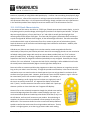
smallest size of you square pixels. However, pixels do not have to be small squares in a grid. LCDs can
be created with “pixels” that are whole images or symbols. For example, an
alarm icon showing a small ringing clock can be done as a single pixel, even if
the icon is not entirely continuous. A 7-segment-like display can be made
with 7 “pixels,” and thus numerical characters can be shown with 7 pixels per
character just like an alarm clock that uses 7-segment LED displays.
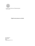
Custom LCDs are also relatively inexpensive though they include some tooling
costs at the beginning where the vendor creates the design you want. You
can choose how the pixels are hooked up, what kind of controller (if any) is on
the LCD device, and how it will connect to your product. Once the design is
complete, the custom LCD can be produced in mass quantity for only a few
dollars each. The instrument shown here has a custom LCD with predefined
symbols as well as dot-matrix areas for writing numbers and letters. The Key
symbol is a single segment, as are the tiny gas names under each reading.
notes_mpgl1_chapter12.docx
Release 1.0
Page 2 of 29
MPG LEVEL 1
12.1.2 LCD Controllers
Making pixels light up is easy in theory and it is barely different than turning on a discrete LED. The hard
part comes more from the physical side of things since, as you have learned, every pixel needs to be
addressed which can result in a lot of hardware to manage. Stand-alone LCDs have a controller chip that
takes care of most of the hard parts about setting and clearing LCD segments. All your host micro has to
do is tell the LCD controller which pixel(s) you want on or off, and it will take care of any addressing,
backplane management or voltage waveform generation to make it happen.
There are a few microcontrollers that have built-in LCD drivers in them. These are peripherals built to
work with LCDs (either custom or standard) and connect directly to the LCD pixel and backplane wires.
The programmer is responsible for all the mapping, though the peripheral provides some help with
backplane management and generates a somewhat complex waveform to make sure all the pixels work
together with their backplanes. The downside of built-in controllers is that they are usually limited
The micro requires connections to GPIO for all the pixel lines, so there will usually be a specification for
the maximum number of pixels that the controller can support (say, for example 16 lines). Since 16
pixels is barely enough to make two characters, the controller will probably support two or more back
planes, each of which require an additional output signal line that is capable of producing a “backplane
waveform.” This brings the total number of pixels that can be supported to (pixel lines) x (backplanes).
So the 16 pixel device that can run 4 backplanes can actually support 64 pixels, and that starts to look a
lot better. For example, you could run six 7-segment characters and still have 22 other symbols
available. However, you still are using 20 pins of the microcontroller which will occupy a lot of the
processor GPIO just for the LCD.
If you need more pixels, then you probably have no choice but to go to an external LCD controller.
There is added cost to this, but also many advantages. Many LCDs are “chip on glass” (COG) which
means you buy the whole LCD and controller as one piece. If it is not a custom design, these can
actually be quite reasonably priced even in low quantity. This is exactly what the MPG LCD is. Other
LCDs might have the glass on a small PCB and have an LCD controller chip on that PCB. Communication
to tell the controller what pixels to light up now takes place with a digital interface like SPI, I²C, parallel,
or others.
12.1.3 LCD Interface
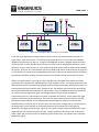
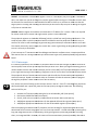
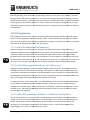
Ultimately, wiring up an LCD system requires three parts as shown in Figure 12.1.3.1.
Figure 12.1.3.1: Three main components in an LCD system
notes_mpgl1_chapter12.docx
Release 1.0
Page 3 of 29
MPG LEVEL 1
The Host Microcontroller is what triggers the LCD controller to drive pixels on or off on the LCD. The
LCD controller takes commands and data from the Host and configures its display RAM that maps to the
LCD pixels. Then the controller updates its output lines that cause the pixels to update on the LCD itself.
The work required to generate the data and organize it into display RAM is pretty much the same in any
LCD system, but the share of the work between the host and the LCD controller can vary significantly.
For most of the basic character display LCDs that you work with, the LCD controller takes care of most of
the work.
The MPG LCD is a very common type of alpha-numeric display. Though this particular display is a twoline by 20-character display, the controller chip will support LCDs down to one-line, 8-characters all the
way up to four-line, 20-characters. The controller chip itself runs a basic application that allows other
devices to send commands and ASCII characters that the controller will interpret. This particular
controller uses an I²C interface which was very important for the development board due to limited
GPIO lines available on the processor. Character LCDs often have a parallel data interface (8 lines) along
with 3 control lines, thus requires 11 processor lines to communicate with. Though that makes them
slightly easier to use since the communication is very intuitive, the hardware overhead can be
impractical.
Correctly attaching the LCD into the development board PCB involves carefully looking at the LCD data
sheet to put the right parts on the board. With I²C, there are only two communication lines, but the LCD
requires additional hardware for the controller to work properly as well as an external interface to the
three LEDs that make up the backlight.
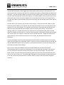
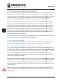
Figure 12.1.3.2 shows the hardware connections as described by the LCD data sheet and the
corresponding hardware connections implemented for the course development board. Note that the
5V rail is used for the LEDs with relatively small resistors so they are quite bright. Since we need to
switch 5V lines, transistor switches are used to help reduce the overall current that the processor will
have to sink when an LED is on. The red backlight LED happens to be connected to an open-drain driver
pin on the processor which cannot drive a transistor switch, so we let that current sink through the
processor.
notes_mpgl1_chapter12.docx
Release 1.0
Page 4 of 29
MPG LEVEL 1
Figure 12.1.3.2: Hardware connections from LCD data sheet (left) and in development board schematic (right)
12.1.4 Character and Control Data
When communicating to an LCD, two modes are used: character and control. This determines how the
LCD controller will interpret the binary data it receives from the host. It is likely that every LCD that you
work with will use this strategy or something very similar
similar. For the course LCD, the mode is selected in
the first few bytes of communication sequence.
If you have not done so already, now
ow would be a good time to open up the LCD data sheet and take a
quick read through to set up the rest of this discussion. A copy of the data sheet is stored on the
Engenuics web site. It is a very good idea to keep a copy of LCD data sheets in particular, because they
tend to disappear from the web on occasion.
http://www.engenuics.com/mpg/hardware/LCD_Character_Newhaven_NHD
http://www.engenuics.com/mpg/hardware/LCD_Character_Newhaven_NHD-C0220BiZ-FSRGB--FBW-3VM.pdf
In character mode, an ASCII LCD will take the bytes you send it with the assumption it is ASCII
AS character
data and light up the correct pixels based. In other words, yyou send the character ‘A’ (0x60) and
magically the pixels required to make an ‘A’ will light up (at the current cursor location).
location) But what really
is happening here? The controller
er sees that you want to write the letter A because you have sent the
character using the defined protocol
protocol. To know what an ‘A’ looks like, the LCD controller has to look up
notes_mpgl1_chapter12.docx
Release 1.0
Page 5 of 29
MPG LEVEL 1
the bitmap for the character that it has stored in its memory that tells it what pixels need to be on to
make an ‘A’ appear. The block of pixels for each character bitmap in this LCD is 5 columns by 8 rows as
shown on the right. Each character can exist at any of the 20x2 character positions
on the display screen. Though each pixel on the screen has an address accessible to
the LCD controller, only full character addresses are used by the host MCU to
indicate where on the screen the character should be placed. Once the bitmap is
determined, the controller can activate the corresponding pixels. While most
character LCDs have built-in bitmaps for at least one font, custom LCDs and many
graphical / dot matrix LCDs do not have any data, so it is up to you provide all the bitmaps. Check out
MPG Level 2 if you want to see an example of a fully customized dot matrix LCD!
In addition to having a font stored in ROM for you to use, there are other features that may be available
to you. For example, the controller allows you to set the cursor position or blank the display. This LCD
even supports a blinking cursor. When characters are being sent to the display, the controller can be set
to automatically change addresses after each character so that it is ready in the correct position when
the next character request comes in on the interface. Instructions to move the cursor to a different
location, erase characters, hide the cursor, erase the whole screen, etc. are also available. These
commands are accessed when the controller is in command mode.
All that functionality is included in the price of the LCD and makes integrating an alphanumeric LCD
relatively easy. The data sheet lists the commands available, the font set available, and the memory
organization of the LCD. The main information is looked at further on in the chapter. We need some of
the data sheet information now because we have to write the first part of the driver to communicate to
the LCD which will handle communication using the I²C peripheral. Though we will make the I²C driver
itself fairly generic, it is important to look for anything specific in the target device’s data sheet to ensure
your driver is going to provide the services needed.
12.2 Inter-Integrated Circuit (I²C) Communication
I²C is a synchronous protocol where the clock is provided by the master in a master-slave relationship. It
uses only a single data wire and can therefore only be half duplex unlike some other standard full duplex
protocols like RS-232. I²C supports multi-master and multi-slave configurations, however we will talk
only about single master (but multi-slave) set ups which are most common in an embedded system.
12.2.1 Legal Stuff
Up until October 2006, any device that used I²C was subject to royalties since the official
standard invented by Phillips (now NXP who makes the MPG LPC processor) was licensed
intellectual property. Designers wishing to build an I²C device and use the I²C logo paid a
fee which was usually incorporated in the device cost so you were not really even aware
of it (though you may wonder why a device with I²C seems a bit expensive).
notes_mpgl1_chapter12.docx
Release 1.0
Page 6 of 29
MPG LEVEL 1
The I²C standard also regulated device addresses. Multi-slave configurations work by using unique
addresses with all the slaves connected on the bus. When a master initiates communication, the first
byte sent is the address of the slave on the bus it wants to talk to. All devices on the bus hear this
address, but if the address is not theirs then they ignore the remaining data until a “Stop condition”
appears on the bus, at which time they start listening for the address of the next transaction. The
protocol started with 7-bit addresses but allows 10-bit addresses these days. Still, that is only 1023
unique addresses, and certainly there are more than that many I²C devices. In fact, some vendors might
have that many parts themselves!
Device addresses are supposed to be grouped depending on their function. As an arbitrary example,
memory devices might be allowed addresses from 0x01 to 0x0F, and accelerometers are allowed 0x10
to 0x1F. The whole concept makes sense until you start trying to manage an exponentially increasing
number of device types and devices within those types. Plus, every other manufacturer was coming up
with their own implementation of I²C that dodged the patent but still allowed compatibility. Lawyers
eventually got involved and decided to find a way around the licensing requirements because it did not
really make sense anymore, and people did not want to pay royalties. In the end, the fee was relaxed in
2006 though a few rules remain.
Nowadays, instead of offering “I²C” communications, a simple “2-wire interface” is offered and the
addressing specification is quite relaxed (though if you want, you can still pay NXP and get an officially
registered address and then probably win in court if anyone’s non-registered device conflicts with
yours). Most companies are careful to never say “I²C” in their documentation, but even that seems to
be a non-issue these days since the legal hoopla around the whole thing has run its course and there are
probably enough court case examples to cite to avoid any litigation. All that being said, if you happen to
build (or integrate) a device with two-wire serial communication and you have not paid to use the name
I²C, then you should probably avoid saying it!
12.2.2 I²C Hardware
Now that we have handled the legal aspects, we can discuss the technical side of I²C. In the hardware
realm, the I²C bus (or two-wire bus) has a serial clock line (SCL) and a serial data line (SDA). The one
data line is used for both transmit and receive data (thus the half-duplex restriction) and device
selection is entirely address-based. That means that regardless of the number of devices on the bus, I²C
only requires two IO lines to hook everything together, making it one of the lowest hardware overhead
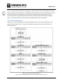
protocols available. Both lines require a pull-up resistor to drive the high state, and all devices use opendrain GPIOs to drive the low state. Figure 12.2.2.1 shows an example of a single master – multi-slave I²C
configuration (the slaves have random addresses that must be unique on the bus).
notes_mpgl1_chapter12.docx
Release 1.0
Page 7 of 29
MPG LEVEL 1
Figure 12.2.2.1: Single-master, multi-slave I²C connections
If you look at the development board schematics for this course, you will see another example of a
single master, multi-slave system. The LPC214x is the master device on I²C0, and the LCD and Blade
daughter board are slaves on the bus. Though you probably do not have a daughter board connected
right now, there are many possible devices that you could tie-in to the development board very easily.
Memories, sensors, input devices, etc. Even things like Arduino shields could be attached and used with
this system. Of course, any custom device you want to build could also be attached as long as you give it
I²C connectivity. No matter how many daughter boards with I²C devices you attached (up to the limit of
the addresses available, anyway), the same two wires from the MCU will be used to talk to them all.
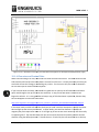
When no communication is occurring we call this the idle state, during which the master and all the
slaves keep their respective SCL and SDA GPIOs in a high-impedance state. Low signals are driven by the
device that has control of the bus lines, but high states are always achieved by resetting the line to a hi-z
state and letting the pull-up do the work. Because of this, the designer must consider the speed of the
bus and the capacitance that each device on the bus adds. There is a tradeoff to select the correct pullup resistor size to get a good low signal level voltage and to minimize current draw during
communication (since in the low state, the resistor is between Vcc and Vss). It also impacts the signal
response time due to the bus capacitance. If there is one master and one slave on the bus, then 10k
pull-ups are usually selected. As you add more devices (or longer bus lengths), the resistor size is
reduced perhaps to 4.7k but may be as low as 1k or less to provide a stronger pull-up. At some point in
the design phase, you should put an oscilloscope probe on SCL and observe the clock signal to
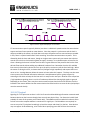
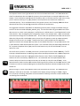
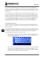
determine if the edges are fast enough. Figure 12.2.2.2 shows a rough example of what the SCL signal
might look like with and without proper pull-ups. System capacitance also plays a role, as does clock
speed. While you will never achieve an absolutely perfect square wave, you should have a reasonably
good quality signal.
notes_mpgl1_chapter12.docx
Release 1.0
Page 8 of 29
MPG LEVEL 1
Figure 12.2.2.2: Signal examples for I²C clock lines
I²C communication speed is typically 100 kHz, but there is a 400 kHz hi-speed version that some devices
support and even faster speeds on newer devices. Since the protocol is synchronous and the clock is
always provided by the master, the clock does not have to be perfect and can start and stop as needed.
In fact, there is a special mode called “clock stretching” that allows communications to pause. This is
allowed by both the slave and master, though on single-master systems only one master has exclusive
control of the clock so clock stretching does not apply. However, it is a valuable option to have for the
slaves. Allowing the slave to hold the clock line low is a great feature of the protocol that lets the slave
do basic flow control without adding any additional hardware lines. Remember that the SCL and SDA
lines are only driven low by devices and it is up to the pull-up resistors to pull the lines back high. When
the master is driving the clock, it releases the line (changes to high-impedance) and expects the line to
return to Vcc. An edge detector allows the master to know when this happens. The slave can take extra
time to process the received information whenever it needs between bytes or groups of bytes by
activating its SCL driver to keep the line low until it is ready for the next byte. Because of the output low
/ high impedance signaling, there is no risk of hardware problems like shorting high signals to ground.
Depending on the master, there may be a certain maximum time that the slave can hold the clock line
low before the master decides that the communication has failed and tries to reset the bus (and perhaps
reset the external device).
12.2.3 I²C Logical
Signaling for I²C is quite neat as there is a fair bit of control and handshaking information communicated
between devices on the bus even though there are only two physical lines. For discussion in MPG (and
probably for most of the systems you will work with), 7-bit addresses will be used which makes it easier
to look at since the complete address is contained in a single byte. If 10-bit address are required, be
sure to set up the I²C peripheral accordingly on both the master and slave(s) on the bus. Some devices
may not support 10-bit addressing, so be careful when specifying parts that will share the same bus.
notes_mpgl1_chapter12.docx
Release 1.0
Page 9 of 29
MPG LEVEL 1
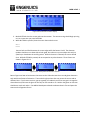
When no communication is taking place, SDA and SCL are high and the bus is idle. To begin
communication, the master initiates a “start condition” on the bus, which is the act of bringing SDA low
while SCL remains high. This transition order is a known special case per the protocol and never occurs
during data transmission so it can be identified by all devices on the bus. As a rule of the system, all
slaves on the bus are normally idle and looking for the start condition to occur. The master then
broadcasts the 7-bit address in the top 7 MSbs of the first byte and adds a read (1) or write (0) bit for the
8th bit (the LSb). The master toggles the clock line for each bit in the address byte, and always adds an
additional clock cycle for a ninth bit. When the slave sees its 7-bit address on the bus plus a read/write
bit, it will acknowledge the address by holding the data line low on the 9th clock provided by the master.
As long as one of the slaves on the bus sees its address, the master will get an ACK and know that the
slave it addressed is ready. This is illustrated in Figure 12.2.3.1.
Figure 12.2.3.1: Start condition and address byte
If the master has sent an address that does not match any of the devices on the bus, then nothing will
hold the data line low and therefore no ACK will be seen by the master. At this time, the master would
set a Stop condition on the bus and then try to figure out why a device that should have responded did
not. There is no provision to handle two devices on the bus with the same address – that is a problem
that is up to you has a designer to avoid. It is also assumed that the master knows what device it
expects to talk to for every given address it uses to communicate. Though there are ways to “discover”
devices on the bus, the most typical applications have known devices at known addresses that the
master uses.
Assuming a device ACKs the address byte, data transfer will begin on the next transmitted byte. All
other devices that did not see their address will ignore subsequent communication for the current
session. If the master is transmitting data to the slave (LSB in the address byte was 0), the slave is
expecting that the next byte on the bus is the first data byte in the transfer from the master. The slave
ACKs every byte sent by holding SDA low at the end of each byte just like it did when it ACKed its
address. The master can continue transmitting bytes for as long as it wants and as long as the slave can
notes_mpgl1_chapter12.docx
Release 1.0
Page 10 of 29
MPG LEVEL 1
handle all the data and keeps ACKing. Once the last byte is sent, the master puts the stop condition on
the bus (SDA goes high while SCL is high) which terminates that communication session.
To receive data from a slave, the master puts a start condition on the bus and sends the slave’s address
with a “1” bit as the LSB. Once the address byte is sent and acknowledged by the slave, the master
assumes the slave is ready to send data and activates SCL to clock in bytes which the slave should be
sending. The master will ACK every byte from the slave during transmission, which indicates to the slave
that it should keep sending data, though it is still up to the master to provide the clock to enable the
slave to send. When the master has had enough data, it NAKs the last byte and then puts a stop
condition on the bus. The master has full control over how many bytes the slave sends.
The question you might be thinking about is how does the slave know what data to send? The situation
depends on what the slave is, as it will have data available in different ways. One of the most common
schemes is setting an address pointer in the slave by writing a register address prior to reading data, and
then clocking out a known number of bytes. Both the master and slave know how many bytes will be
sent for any given transaction. The master might also tell the slave how many bytes it is looking for,
which requires the master to first address the slave with a write to send it a command or other
information to setup the data transfer. The master would terminate the write frame, and then
immediately start another frame but this time in read mode. The slave, having just been told what the
master is looking for, can then expect to provide the data to the master.
A complete I²C read transaction might proceed like this:
1. Master issues start condition and sends slave’s address with write bit
2. Slave acknowledges the write address
3. Master transmits the start address that it wants to read data and the number of bytes it wants
to read
4. Slave acknowledges each data byte and knows what the purpose of each byte is based on a
predefined protocol
5. Master issues a repeated start condition (which is essentially a stop condition and then a start
condition)
6. Master transmits the slave’s address with the read bit
7. Slave acknowledges the read address
8. Master clocks in the number of bytes it wants, ACKing each one as it is received
9. Master NAKs the final byte to confirm it is done and puts the stop condition on the bus.
Typically the slave is set up to read the register address the master sends and set a pointer to that
location in memory. The slave will then automatically increment its internal pointer after every byte it
sends. In a simpler case, a slave may only have a single register to output so the same data is sent each
time (like an 8-bit temperature sensor). In this case, the master would only ever have to read data and
notes_mpgl1_chapter12.docx
Release 1.0
Page 11 of 29
MPG LEVEL 1
not worry about specifying an address or sending commands.. If the master tried to read multiple bytes,
then it might just keep getting the same information over and over again. There are lots of scenarios
that you can come up with that may need to be handled depending on the system you are working
worki with.
Regardless of what you are trying to communicate with, tthe
he key is to read the device datasheets
datasheet to see
what it can do and how to do it. You may then write a specific driver set to run with your system to
access the slave, or it might fit in with a more generic I²C driver you can write. At the very least, you can
write generic I2CStart(), I2CStop() and I2CData(
I2CData() functions, and incorporate the target device protocol
within an application state machine th
that will read or write data use the base functions..
The last feature of this protocol to mention is the reserved addresses in the scheme, of which there are
five or six. The one you see the most and will prob
probably
ably use is the “general call” or generic address, 0x00.
All devices will listen to the general call address and ACK it, and will then receive a single command byte.
These special addresses and data bytes along with every other detail about I²C can be found
fo
on
www.i2c-bus.org.
I²C tends to be a very popular choice for on
on-board
board communications in an embedded system due to the
addressing capability and simple hardware requirements
requirements,, though some high throughput devices
requiring more speed may choose a different protocol
protocol.. No matter how many devices you have on the
bus (as long as you do not go over some physical resistive and capacitive limitss or the physical address
size),
), you only ever need two GPIOs on your microcontroller. You
ou can probably make a safe bet that you
will implement I²C at some point in your embedded career.
12.3 Implementing I²C on the LPC214x
Hopefully the implementation of I²C does not sound too complicated. Though there is certainly more
involved than with RS-232,
232, I²C is still relatively simple. Whil
While
e most MCUs have I²C peripherals now, you
still might end up bit-bashing
bashing a driver if you are working with some legacy product or if you run out of
peripherals on your microcontroller. That becomes a bit challenging and you would need to do some
further investigation
vestigation to understand and implement the full I²C protocol. As far as writing the driver for
the course, we will make use of the I²C peripheral on board the LPC214x and write a nice little driver for
all of our needs. Download the Chapter 12 start cod
code
e now if you have not yet already done so.
We will focus on master mode only and consider just transmit functions. Because of the way that this
peripheral works, interrupts are essential. There are quite a few things to take care of to make
everything work the way we want.
1. Peripheral configuration in ii2c_lpc214x.c/h.
2. Interrupt configuration and handler in interrupts.c/h.
3. I²C application initialization and operation
operation.
notes_mpgl1_chapter12.docx
Release 1.0
Page 12 of 29
MPG LEVEL 1
12.3.1 I²C Peripheral Registers and Configuration
This peripheral is a bit more complicated than the peripherals we have worked with so far, but that is
because it has a lot more to do. The peripheral itself operates as a state machine and is quite strict in
how it implements the I²C protocol. It is definitely different than some other microcontrollers where the
I²C peripherals are much more manual in their operation. Remember that the microcontroller vendor,
NXP, is responsible for adding all the peripherals to make up this microcontroller, so this I²C peripheral
hardware is specific to NXP. If you work with an ARM7 core on a different vendor’s microcontroller, all
of the peripherals will be different – some substantially so – than this one. The good news is that if you
stay with NXP, then you will see very similar peripherals on other processors in their ARM family (ARM7,
ARM9, Cortex-M3, etc.) and may be able to easily port over your code.
The I²C chapter in the processor reference guide is quite lengthy, but there is a lot of information that
does not apply to the case we want to design for. You can ignore anything that talks about slave mode
since we will use master mode exclusively. You can also skip all of the details on how the bus works
since that information has already been covered in these notes (though if you want a second
explanation, take a read from NXP!). As we have done many times before, reading through the register
description is essential to correctly set up the peripheral registers. Lastly, there are four pages that are
worth printing for developing the algorithm that works with the peripheral’s state machine – the Master
Transmit and Master Receive mode transmit flowcharts on pages 224 and 225, and the corresponding
status code tables on page 228 and 229 of the Rev. 3 October 2010 guide. If you print them 4-up on a
single page you will have all the information you need to reference at hand.
As it turns out, there are not that many registers involved with the I²C peripheral. Most of the available
registers are used while the application is running, so very little setup is required.
I2CxCON: Control register accessed through I2CxCONSET and I2CxCONCLR. Only the interface enable bit
(bit 6) needs to be set by writing 0x40 to the set register. Other bits are used to initiate I²C actions like
Start and Stop conditions, and some bits provide status information.
I2CxSCLH and I2CxSCLL: Duty cycle configuration registers. These hold the number of processor
peripheral cycles that the serial clock signal will spend high and low. Remember from the UART baud
calculation that the peripheral clock, PCLK, is set the same as the main clock of 12MHz. If we target a
100 kHz I²C clock, a full period is 1/100 kHz = 10us. With 50% duty cycle, the high and low times are
both the same duration and equal to half the total period, 10us / 2 = 5us. To pass 5us with a system
clock period of 1/12MHz = 83.3ns, we need 5us / 83.3ns = 60 = 0x3c. Note that for higher speed
communication, the I²C specification requires a non-50% duty cycle, so these registers will not always
necessarily match.
I2CxSTAT: Status register. Bits 3-7 hold a status code that will guide your application through the I²C
state machine. More on this later.
notes_mpgl1_chapter12.docx
Release 1.0
Page 13 of 29
MPG LEVEL 1
I2CxDAT:: Transmitted or received data register. Since I²C is half
half-duplex,
duplex, only one register is needed for
data. Just make sure you do not forget to read this register before writing to it if data has arrived!
arrived Note
the bit order for transmission is not selectable for MSb or LSb first,, so you have to make sure that the
target system is sending and receiving the same else you will have to fl
flip
ip bits prior to writing the register
or flip bits on received data.
I2CxADR:: Address register that sets the microcontroller’s I²C address if it is a slave. This is not required
for master mode since a master in a single
single-master system is never addressed.
The peripheral registers are loaded in I2C0Setup() which is called from main() during initialization. The
setup function power cycles the peripheral with the PCONP bit and the peripheral enable bit to try to
ensure a full reset in case something has gone horribly gone and setup is called when the bus is not idle.
This should, technically, never happen
happen,, but a stuck bus is never a good thing so doing everything possible
to start it correctly is worthwhile.
If you interrupt an I²C transaction with the debug
debugger
ger and then do a software reset, it is quite possible to
have the bus stuck in a strange state that you cannot seem to get out of without power cycling the whole
board.
12.3.2 Interrupts
It is virtually impossible to use the NXP I²C peripheral without int
interrupts and get any decent transmit or
receive speed, so we will set up the required interrupt driver now. While you might be thinking you will
need to enable transmit and receive interrupts just like in the UART, the I²C peripheral happens to have
just a single interrupt signal and enabling a single bit in the VIC is all it takes to make the interrupt active.
The peripheral relies on firmware to read a status code that tells the firmware what just happened to
cause the interrupt.. Based on the status ccode,
ode, our firmware will take the necessary action to progress
through the peripheral’s state machine as we will see shortly.
First, do the easy task of setting up the interrupt source in the VIC. Since I²C is handling fairly important
data and the data rate
te is quiet fast, make its interrupt priority the highest under IRQ. The
T following
tasks are left for you:
1.
2.
3.
4.
5.
Activate the I²C0 interrupt by setting the bit in VICIntEnable_INIT (interrupts.h)
Declare the I2C0ISR function (interrupts.h)
Set VIC_I2C0 as the first priority in IRQ and shift the others down (interrupts.h)
Add/adjust appropriate initializations for the updated VICVectCntlx registers (interrupts.c)
Add/adjust appropriate initializations for the VICVectAddrx registers (interrupts.c)
After some playing
ing around with this I²C peripheral, the best strategy for implementing the driver was
determined which involves doing quite a bit in the interrupt handler. TThe ISR code ends up looking fairly
long and integrated into the I²C functionality
functionality, which goes against
inst the preferred guidelines of writing
short, non-integrated
integrated ISRs. However, the nature of the communication protocol practically demands it
notes_mpgl1_chapter12.docx
Release 1.0
Page 14 of 29
MPG LEVEL 1
and even though there is quite a bit of code, only a few lines get executed for any given interrupt. The
first version of this driver relied on disabling and enabling interrupts all over the place to avoid having a
lot of code in the ISR, though there was still a fair amount in there. You might say it was resisting the
way that the peripheral intended for it to be used and was rather ugly and almost impossible to describe
in notes. So a second version was written for the course and follows the intended flow dictated by the
I²C peripheral. You might want to take a few moments to think about how you might design it a
different (a possibly better) way! Note also that we are writing the ISR very specifically for I2C0 and only
worrying about the transmit case since the development board LCD cannot send back data that we
would have to receive. So it is really only half done and not very generic, but could be easily completed
and applied to other I²C peripherals when required.
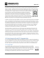
Look at the I2C0ISR handler in interrupts.c, which is partially finished in the “start” code. At the same
time, look at the I²C peripheral state machine flowchart on pg. 224 of the reference guide. Figure
12.3.2.1 below shows the relevant portion of the flowchart that the ISR will handle.
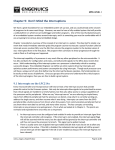
Figure 12.3.2.1: I²C peripheral flow chart: Master Transmitter
Source: LPC214x User manual Rev. 3 – 4 October 2010, pg. 224, NXP Semiconductors, UM10139.pdf
notes_mpgl1_chapter12.docx
Release 1.0
Page 15 of 29
MPG LEVEL 1
Each of the red circles is the status code that will be present in I2C0STAT after the I²C interrupt occurs.
I2C0ISR() parses the status code with a switch statement to determine the next action. While the
interrupt flag bit remains set (it was set to trigger the ISR), the I²C peripheral is waiting to continue and
will not carry on until the interrupt flag is cleared. The peripheral proceeds immediately once the flag is
clear, which brings about the trickiest part about writing code for this peripheral and thus necessitates
taking action inside the ISR.
What has to happen in firmware ends up breaking down quite easily once you have spent some time
trying to figure out what exactly is going on and how it all works. Debugging skills are important for
something like this to be able to step through code in the main application and interrupt service routine
while ensuring you observe the right peripheral registers. An oscilloscope is nice to have, too, but not
entirely necessary. The difficult part is understanding what triggers advancement to the next state in
the I²C peripheral state machine. To sum it up simply, you must always do things in this order:
1.
2.
3.
4.
Interrupt occurs
Write the I²C data register with either the external address or the data byte you want to send
Clear the interrupt flag
Exit the interrupt service routine
You MUST write the data byte before clearing the interrupt flag, because as soon as the flag is cleared
the I²C peripheral advances states and will send whatever is in I2C0DAT even if the program counter is
still stepping through I2C0ISR. Since you have to clear the flag to get out of the interrupt service routine
and back to your main program, you have (almost) no choice but to update I2C0DAT within the ISR. If
you are sending a long message, that means you have to manage the transmit buffer in the ISR, too.
For the record, you could disable the I²C interrupt inside the ISR and then avoid clearing the interrupt
flag until you have loaded I2C0DAT inside your I²C application. This would let your main program
control the peripheral writes and avoid doing it in the ISR. It does not end up working very nicely though
and requires considerable effort to work around what the I²C peripheral really wants to do.
During the main program, the I2C0ISRs take care of the entire message transmission. The I²C application
is responsible for setting up the message to be sent and initiating the Start condition that gets the I²C
peripheral going to transmit the message. Once that has stared, the application simply waits for all the
bytes in the message to be sent while watching for an error or timeout. The only exception is during
LCD initialization where special timing requirements of the LCD controller during initialization make the
interrupt-driven approach unfeasible. So this will be handled as a special case with interrupts off. Once
you see the I²C application in the next section this will make sense, and then you will be able to add the
necessary code to the ISR.
Some oscilloscopes and logic analyzers have software I²C serial decoders for those times when you need
to do some serious debugging. These would be most likely be used to find data errors or problems
between two devices communicating back and forth with hundreds or thousands of transmissions.
notes_mpgl1_chapter12.docx
Release 1.0
Page 16 of 29
MPG LEVEL 1
12.3.3 I²C application initialization and operation
The I²C application occupies i2c_lpc214x.c/h and holds the specific functions to run the peripheral and
handle messaging. On its own, it does not really do anything and there is not really any test functions
fun
that can be written just for testing the I²C peripheral. If you really wanted to test the driver, it would be
a great idea to hook up I²C0 to I²C1 and run a few billion bytes between the two peripherals over a
weekend. However, our development boa
board
rd exercise does not require such thorough testing.
The set of functions you would find in an I²C driver file will most likely include some initialization plus
Start(), Stop(), Write() and Read()
() functions that interface directly to the peripheral – these are the
staples of any I²C peripheral regardless of processor. By building a standard interface to those functions
and using them in the rest of your code, you get good abstraction from the hardware and thus good
portability for the higher level part of the driver. The function implementations are mostly done, but
you need to complete I2C0Stop(). All of these functions are considered protected. They are not private
because some low-level
level access will be required from the LCD application and possibl
possibly from other I²C
device
evice applications that use the same bus.
Three other functions are specific to this driver implementation, so we will take a quick look here along
with a look at the state machine that monitors data transmission
transmission.
12.3.3.1 void I2CForceSend(void)
As you have seen with other applications, a “manual mode” for the state machine is necessary so the
application can be used during initialization when the regular main program loop is not running.
12.3.3.2 bool QueueI2C0Message(u16 u16DataSize_, u8 *pu8Data_)
This is the one and only public API function that other applications will use to queue messages to the I²C
peripheral for transmission. It takes an array of bytes along with the size of the array so exactly the right
amount of memory can be allocated and we do not have to worry about parsing termination characters.
It is up to the calling application to correctly format the message, including getting the right target
address with read/write bits as the first byte and all the other bytes in the right place
e so the message
makes sense to whatever will receive it.
Messages are kept in dynamic memory in a linked list. There is no error checking beyond some while(1)
traps to ensure that there is enough space on the heap to accommodate all the messages that might
m
be
queued. However, it is not expected that any problems would occur in this system given the small
amount of messaging taking place to the LCD. That might not hold true for other systems, so be sure to
code accordingly!
Dynamic memory is often “outlawed”
tlawed” by companies because of the potential chaos that could result
from heap overflow and/or memory leakage. Be sure you know the acceptable practice when you write
code for someone.
notes_mpgl1_chapter12.docx
Release 1.0
Page 17 of 29
MPG LEVEL 1
12.3.3.3 void DeQueueI2C0Message(void)
As you can guess, this function
n takes care of cleaning up the transmit linked list for the message that was
just sent. The I²C state machine takes care of calling this function, so it is considered private. Removing
the responsibility of managing dynamic memory correctly from the use
userr of the class is a great way of
ensuring no heap-related
related errors will start appearing in the system. Since you probably love managing
linked lists correctly, the implementation of this function is left for you to do in the code, though the
completed function
ion is shown below.
void DeQueueI2C0Message(void)
{
MessageStructType *psNextMessage = NULL;
if(GGsI2C0CurrentMessageToSend != NULL)
{
/* Point to the list node after the doomed node */
psNextMessage = GGsI2C0CurrentMessageToSend
GGsI2C0CurrentMessageToSend->psNextMessage;
/* Kill the doomed node's data and the doomed node itself */
free(GGsI2C0CurrentMessageToSend
free(GGsI2C0CurrentMessageToSend->pu8MessageData);
free(GGsI2C0CurrentMessageToSend);
}
/* Update the list pointer to the new first element */
GGsI2C0CurrentMessageToSend
entMessageToSend = psNextMessage;
if(GGsI2C0CurrentMessageToSend == NULL)
{
LGsMsgLastMessage = NULL;
}
} /* end DeQueueI2C0Message() */
12.3.3.4 I²C0 State Machine
Since most of the work of sending data is taken care of by interrupt
interrupts, the state machine for the I²C driver
is fairly simple. The state diagram for the system is shown in Figure 12.3.3.4.1.
The Idle() state monitors the transmit buffer pointer and does nothing unless a message has been
queued. When a message is ready, it in
initializes
itializes a timeout counter and uses I2C0Start() to kick the
peripheral into action. As soon as that is done, I2C0ISR() will take care of sending the message out.
notes_mpgl1_chapter12.docx
Release 1.0
Page 18 of 29
MPG LEVEL 1
Figure 12.3.3.4.1: I²C application state diagram
The I²C application waits in the SendingData() state looking for either an error, timeout, or the current
message size counter reaching 0. Given how short a typical LCD message is, the message is probably
finished transmitting by the time the next 1ms period expires and SendingData() is called the first time.
This is in sharp contrast to the UART driver we built where transmitted bytes were sent once per 1ms
iteration since the baud rate was just 9600bps with two bits of overhead per byte. At 100,000bps and
only 1 overhead bit per byte, the I²C driver is way faster!
If an error has occurred, the application goes to the SendingError() state which does not do too much
right now beyond stopping the bus and getting things ready for the next message. In the current
implementation, the message that was being sent would be lost if an error occurred. You could add
some additional code to feed back information to any application that queued the message so that it
notes_mpgl1_chapter12.docx
Release 1.0
Page 19 of 29
MPG LEVEL 1
could decide whether or not to resend the message. One co
could
uld argue both ways that the I²C application
should or should not guarantee that it delivers a message it was given to send. Once again, the
programmer is faced with choosing trade-offs
offs in designing for the needs of any particular system.
After the errorr state, or if a message has been transmitted successfully, the SendDone
SendDone()
() state is active.
SendDone() exists as its own state to give a common conclusion to a cycle through the state machine. It
takes care of freeing the memory for the current message aand
nd returns the application to Idle. It will
never run for more than one consecutive cycle as it does not wait on any event. Like SendingError(),
SendDone() could be used to provide more insight back to other applications on the status of the
transmission.
12.4 Using the LCD Controller
Now that we have the mechanism for communication to the LCD, it is time to program an interface to
the controller to allow access to configuration and message display on the screen. Fortunately, alphanumeric displays with an ASCII interface are pretty easy to use since the built-in
in controller will handle
the somewhat complex pixel driving tasks
tasks. All we need is to program the interface to meet the protocol
and write some functions to send character updates. If you have not read the data sheet for the LCD
yet, you pretty much cannot go forward without doing so. What you need to note from the data sheet
now are five things:
1.
2.
3.
4.
5.
LCD I²C address
Control byte
Character RAM addresses
LCD command set
LCD initialization sequence
Note that the data sheet linked on the course website is prepared by the LCD vendor, Newhaven
New
Display, and describes the complete LCD and not just the controller. That being said, much of the
information is a subset of the full LCD controller data sheet that you can find via a link in the same data
sheet. The controller’s data sheet is 70 pages long and contains a lot of information that you do not
really need to use the LCD, though you may want to browse to learn more. Newhaven’s data sheet
captures thee most useful information from the controller information along with the relevant hardware
references, electrical specifications and example code for initialization. There are a few details that did
not make it over that might be nice to know, such as how the I²C version of the controller only supports
Write mode (see page 14 of the controller data sheet)
sheet).. Both documents have the drawing shown in
Figure 12.4.1 that we will reference several times in the following sections.
notes_mpgl1_chapter12.docx
Release 1.0
Page 20 of 29
MPG LEVEL 1
Figure 12.4.1: I²C command example from controller specification
Source: Sitronix ST7036 Dot Matrix LCD Controller/Driver data sheet, pg. 16
12.4.1 LCD Address
The address byte is the first byte sent to an I²C device after the start condition. Remember that the I²C
standard dictates that device addresses are 7 bits in length plus the Read (1) or Write (0) bit that is
always the LSb. Specifying the device address does not seem to follow a standard form. For example, if
the address of a device is given as 0x64, that might mean the full 8-bit address byte you send to Read
the device is 0x65 once you set the LSb high to indicate Read, or it might mean that the first 7 bits are
0x64 (b’1100100x’) and you need to add an 8th bit for x=R/W. We attempt to illustrate this in Figure
12.4.1.1. but admittedly it is a little hard to explain in text.
0x64 Specified device address
MSB
0
0
1
1
6 5 4 3 2 1 LSB Comment
1 1 0 0 1 0 0 Specified address includes the R/W bit - "Write" address is 0x64
1 1 0 0 1 0 1 "Read" address is therefore 0x65
1 0 0 1 0 0
1 0 0 1 0 0
0
1
Address was meant as only upper 7-bits - "Write" address is 0xC8
"Read" address is 0xC9
Figure 12.4.1.1: Illustration of how a specified I²C address can mean several things
Fortunately, in the case of the LCD controller, the diagram in 12.4.1 shows the actual bit detail of the
address byte so you can deduce that the write address is b’01111100’ = 0x7C. Unfortunately, that is
NOT what the device address is. If you dig through the longer controller data sheet, you will find some
explanation on page 16 that describes four different possible addresses that the controller can be set to.
The address that Newhaven picked happens to be different than the one the LCD controller vendor
picked for their example.
notes_mpgl1_chapter12.docx
Release 1.0
Page 21 of 29
MPG LEVEL 1
Regardless, the Newhaven data sheet says in large bold letters that the address is 0x78 but they fail to
mention which of the above formats that value is in. With a quick bit of testing, the complete LCD Write
address byte was confirmed as 0x78, so this particular specification format matches the first case shown
in Figure 12.4.1.1. This address is captured as a constant in the header file, LCD_ADDRESS_WRITE. This
test was carried out during driver testing to confirm that it was acknowledged by the LCD. Fortunately,
that part of the example code was correct. Imagine if you were not sure if you had the correct LCD
address and spent hours (or days) debugging your I²C driver and/or board hardware because the LCD
refused to respond to its address, only to (finally) try changing the address and discover that everything
was working just fine! It is problems like that which are extremely frustrating, especially with the tight
deadlines that you will always have in industry.
12.4.2 Control byte with Co and Rs
Communicating to the LCD requires following a strict input and output protocol that is very typical of
any MCU-IC interface. After LCD controller acknowledges its address, the next byte sent must be a
control byte that has two important bits called Co and Rs. Rs is the bit used to tell the LCD if the bytes
that follow are meant as control codes or simply data that should be written to the screen. If you read
the controller data sheet, you will see a truth table that shows that Rs works in conjunction with the
R/W bit to get four different modes from the LCD controller. However, as we have mentioned already,
the I²C version of the LCD controller does not support Read operations, so there is only in fact two
modes that can be accessed:
•
•
Rs = 0: Instruction mode
Rs = 1: Data mode
The Rs bit works in conjunction with the Co bit.
•
•
If the Co bit is set, then the next byte sent will be interpreted as a data mode byte or instruction
mode byte depending on what Rs was. The byte after will be interpreted as another control
byte allowing you to change the Rs bit and thus toggle between data or instruction mode.
If the Co bit is clear in the control byte, then the controller assumes that all subsequent bytes in
the transmission session are of the same Instruction mode or Data mode that is indicated by Rs
so you can send a series of bytes in the same mode.
In other words, the Co bit allows you to change modes during a transmission session. There might be a
scenario where you wanted to send a command byte, send a data byte, send another command byte,
send another data byte, etc. There would be some extra overhead if you had to set a stop condition and
restart a new frame each time you wanted to change modes. However, this scenario is unlikely to occur
so the Co bit tends to be unused. For all of the communications in the driver we build here, Co is always
0 so each transaction will only ever be a bunch of commands or a bunch of data. If we need to switch
modes, the session will be stopped and a new one started.
notes_mpgl1_chapter12.docx
Release 1.0
Page 22 of 29
MPG LEVEL 1
12.4.3 Character RAM Addresses
This particular LCD controller supports screens up to 20 columns x 4 rows. The ASCII character data that
ends up being displayed on the screen is stored in the controller’s “Display Data RAM” (DDRAM) in
which there is 80 bytes of space. Even if you have an LCD screen that is smaller than that, you can still
write to all the character addresses and the data will be stored but not displayed beyond the addresses
that are visible on screen. You can use the non-displayed area as general purpose RAM if you really
wanted to, or make use of the shifting features to do some message scrolling. For the 20 x 2
implementation of the course LCD, the RAM is organized as shown in Figure 12.4.3.1 from the LCD
controller data sheet. Note that the Newhaven LCD data sheet shows an address range for a 16 x 2
display instead of a 20x2 display.
Figure 12.4.3.1: LCD Character RAM
Source: Sitronix ST7036 Dot Matrix LCD Controller/Driver data sheet, pg. 16
The displayed characters for Line 1 will be at addresses 0x00 thru 0x13 and hidden characters will be at
0x14 thru 0x27. Line 2 visible addresses are 0x40 thru 0x53 with hidden characters 0x54 thru 0x67. The
second part of Figure 12.4.3.1 shows what happens when you request a shift command (either left or
right). For Line 1, a left shift moves the displayed character range to 0x01 – 0x14; a right shift displays
notes_mpgl1_chapter12.docx
Release 1.0
Page 23 of 29
MPG LEVEL 1
0x27, 0x00 – 0x12. Line 2 has similar behavior with the important concept being that each line rotates
through itself.. What all this means is that you should be able to do a bunch of neat scrolling effects on a
per-line basis just using controll commands to shift the display
display. The only limitation is that
hat there is just a
single shift command so both lines would have to scroll. However, the scrolling behavior does not work
like you might expect. Try it during the chapter exercise, but you will find that it will not really work for
what the exercise requests you to do.
Scrolling displays aside, you need to be comfortable with the character addressing since you must use it
to position the cursor where characters will be displayed. You can write to any location on the screen
first by setting the cursor address, then by loading a message.
12.4.4 LCD Command Set
Randomly sending bytes to the LCD will not get you very far – you must use the defined command set to
talk to the device correctly. The complete sset
et of commands that you need is shown on pages
page 7 and 8 of
the Newhaven LCD data sheet. Any command whe
where
re the R/W bit is 1 (Read) is not available in I²C mode.
Most of the commands are pretty obvious for what they do. Many of the commands have configurable
configurabl
bits that need to be set or cleared depending on what you want to accomplish. For example, the Display
ON/OFF command is shown as b’00001DCB’ so the actual command is b’00001xxx’ with three
configurable bits (see Figure 12.4.4.1)
12.4.4.1). The command description
on tells you what the individual bits do.
Figure 12.4.4.1: Display command example
Source: Sitronix ST7036 Dot Matrix LCD Controller/Driver data sheet, pg. 25
The LCD controller data sheet offers further description of each command and its parameters if you
require it. There are some commands like for setting hardware behavior that, to use correctly, you
would have to do some reading in the controller data sheet and/or test out some settings. However,
Newhaven has done this already and included the iinformation
nformation in their suggesting initialization sequence
that is discussed in the next section. The only one you might want to play with is the Contrast Set
command if your display contrast needs adjustment.
All of the command literals have already been se
set up in lcd_nhd_c0220biz.h – open up this file and the
source code file if you have not done so yet
yet. Most can be used directly, but some, like the Display
command above, require you to use a base command word and OR in some other flags that you want
set. The Display command shown below uses LCD_DISPLAY_CMD as a root and adds bits to turn the
display on, make the cursor visible, and blink the cursor. All those values get packed into a single byte
by the compiler so there is no code penalty in using this m
method.
I2C0Write(LCD_DISPLAY_CMD | LCD_DISPLAY_ON | LCD_DISPLAY_CURSOR | LCD_DISPLAY_BLINK);
LCD_DISPLAY_BLINK
notes_mpgl1_chapter12.docx
Release 1.0
Page 24 of 29
MPG LEVEL 1
If you are working with a new device, be prepared to spend the time to build a good header file with all
of the protocol constants written out. Depending on the type of device you are working with, this might
take a few minutes or it might take hours. However, it is worth the time and will save you much
frustration continuously referencing the data sheet and/or hard-coding values without meaningful
names. Check with the vendor to see if they have a header file that you can download.
12.4.5 LCD Initialization
Before you can start sending regular commands and data to the LCD, it must be initialized in a very
specific way (see Figure 12.4.5.1). If you do not follow this sequence, then the LCD will likely not
function correctly.
Figure 12.4.5.1: LCD Initialization sequence
Source: Sitronix ST7036 Dot Matrix LCD Controller/Driver data sheet, pg. 41
notes_mpgl1_chapter12.docx
Release 1.0
Page 25 of 29
MPG LEVEL 1
The sequence shown in the figure is taken from the LCD controller data sheet. The LCD module data
sheet from Newhaven does
oes not show this sequence, but instead shows an example initialization code
snippet. Since initialization requires specific time delays and our LCD state machine is not even running
yet, the function LCDInit() in lcd_nhd_c0220biz.c that implements the in
initialization
itialization uses the I²C
commands directly. This is another violation of our general system rules of keeping individual drivers
abstracted from others, but working around this would be too cumbersome.
The suggested initialization sequence from Newhaven generally works, though the LCD will often get
stuck on the lastt command 0x06 (LCD_DISPLAY_ON). The command does not get ACKed so the screen
does not turn on, which is why every byte is verified that it is ACKed when it is sent from the MCU to the
LCD controller. Upon investigation, the timing delays shown in the example code – which are assumed
to be 10ms even though that is not made clear -- do not match the specification from the LCD controller.
When the LCD controller initialization process is used, the LCD appears to start up more consistently
though still suffers errors on occasion
occasion. Therefore the driver code provided uses the controller’s
algorithm instead of the example start
start-up shown in the module data sheet. The
he byte verification is left
in place because it adds robustness
tness to the system – this is the kind of fail-safe
safe code that you would use
for a commercial product where “just press the reset button to try the LCD initialization” is not an
option for a user.
All the LCD start-up
up code is in LCDInit() and it uses a private helper function called LCDWaitSI().
LCDWaitSI() The I²C
interrupt is disabled because of the timing requirements and delays between each command byte sent.
The LCD’s hardware reset line is managed and the function returns TRUE or FALSE depending on
whether the LCD is successfully
fully initialized or not. The commands that are sequentially sent with
common delays are listed in an array so that they can be index in a loop for code efficiency. As an
optional exercise (and since there has not been anything really ffor
or you do to in this whole section!), take
a moment to verify the command list against the specified initialization flowchart and the values in the
header file.
Before moving on, test to make sure the LCD on your board starts up correctly. Put a breakpoint on
LedInit() in main and run the code. You should see the display startup message as shown in Figure
12.4.5.2 (cursor is blinking). Adjust one of the command
commandss in LCDInit() so that the cursor is hidden and
not blinking after initialization.
Figure 12.4.5.2: Successful LCD initialization with blinking cursor
notes_mpgl1_chapter12.docx
Release 1.0
Page 26 of 29
MPG LEVEL 1
Generally speaking, the first time you get something to show up on an LCD is very exciting! If it shows
what you expect and does so consistently
consistently,, that is even more exciting. By getting to this stage, we have
proved that the I²C driver is functioning, the LCD hardware is hooked up correctly, the LCD command set
is working and the initialization sequence is correct. Given all the things that could go wrong, it is a fair
achievement to get to this point. Now comes the easy part of using all the low
low-level
level drivers to build the
LCD application.
12.5 LCD Application
Even though the lead-up
up to this point has required a great d
deal
eal of thought and effort, the final code to
write for the LCD application ends up being very simple. The LCD functionality that will be provided is
with a set of three API functions that queue appropriate messages to make the LCD perform as required.
Thee functions provided are described in the next sections.
12.5.1 void LCDCommand(u8 u8Command_)
Sending commands is an essential part of using the LCD, especially since the calling application is
completely responsible for managing what is on the screen. Moving the cursor and clearing the screen
will likely be used most often,, but any of the commands might come in handy
handy.. The single function
parameter takes a literal from the list of LCD Commands in the LCD header file, adds the command into
the last location
ion in the command array, and then queues the array to the I²C application. The array is set
up for you, it is up to you to add the two lines of code to update the array and queue the message.
12.5.2 void LCDMessage(u8 u8Address_, u8 *u8Message_)
Loading a character message is the next obvious thing you would want to do. The function takes the
LCD address for the first character in the mes
message, and a pointer to a NULL-terminated
terminated message string.
A command is queued to set the cursor to the desired address
address,, then a message array is populated with
the message characters while a character count is kept. Once all the characters have been loaded in the
array, the message and its determined size are queued to the I²C app.
To make this function a little more robu
robust,
st, you could add checks to see if the characters available based
on the address provided would
ould fit the intended message. At the very least, you could truncate the
message to the available space. Perhaps the function could return a value based on the success
su
of the
message or not. You could also add arguments to automatically clear the screen or the line on which
the message will be displayed.
12.5.3 void LCDClearChars(u8 u8Address_, u8 u8CharactersToClear_)
The last handy function is one that will clear a smaller group of characters from the screen instead of
using the clear screen command that wipes out all display RAM
RAM. This is useful for user interfaces or for
certain displays where values are changing but you do not want to refresh the whole screen.
sc
The
parameters are a start address and number of characters to clear. It works almost identically to
LCDMessage(), so it is left as an exercise for you to write.
notes_mpgl1_chapter12.docx
Release 1.0
Page 27 of 29
MPG LEVEL 1
As the LCD functional requirements evolve, it will likely make sense to add an LCD sta
state
te machine to
handle more complex behavior at which point the three API functions would probably become private
to the LCD application and a slightly different interface would be provided to applications that would use
the LCD service.
nt to provide vertical or scrolling message capability native to the LCD
For example, perhaps you want
driver rather than leaving it up to a client application to take care of that (as you will do in the chapter
exercise). An application could send text continuously to the LCD which ccould
ould buffer the strings and
display them systematically on screen (e.g. the first message could be displayed for one second on line
1, the 2nd message would be displayed on line 2, and then every subsequent message would be added
on line two and bump up thee current line 2 message to line 1). It is hard to know exactly what
functionality would be desired, so for now we will leave the driver in this state with the basic API.
12.6 Chapter Exercises
This chapter exercise starts out quite similar to Chapter 11 but instead of printing characters out the
UART port, characters are printed to the LCD. Copying the relevant part of the Chapter 11 solution will
get you going quickly!
Complete the following exercises in chapter12.c/h
chapter12.c/h. All the exercises’ functionality
ity should be present in
the final code.. In the solution provided, each part modifies some of the previous parts, so the solution is
not completely sectioned out for each exercise,, but you should be able to see how the complete
solution progressed especially when you start your own version.
1. When BUTTON1 is pressed, output the string “The counter is: “ followed by the 4-digit
4
counter
on Line 2 as shown in Figure 12.6.1. Each time the button is pressed, overwrite the value on
Line 2 with the new counter value
value.
Figure 12.6.1: Exercise 1 solution display
2. Adjust the code so that
hat the first instance of the counter output prints on Line 2,
2 and subsequent
instances print on Line 2 and bump the previous line up as shown in Figure 12.6.2. You must
keep a copy of the current Line 2 and rewrite it to Line1 (i.e. you are not allowed to regenerate
regener
the text on Line 1). Hint: <string.h> is included in this package.
notes_mpgl1_chapter12.docx
Release 1.0
Page 28 of 29
MPG LEVEL 1
Figure 12.6.2: Exercise 2 solution display
3. Make BUTTON2 clear the screen and reset the counter. The counter string should begin printing
on Line 1 next time you press BUTTON1.
4. While BUTTON3 is pressed, clear the screen then make the text
MPGL1
ROCKS
bounce back and forth between the screen edges while the button is held. The character
updates should occur at about 4Hz to look good, but make sure you can adjust this easily to
speed up or slow down the scrolling action. When the button is released, the screen should
clear. While BUTTON3 is pressed, do not respond to any other buttons. Three frames are
shown in Figure 12.6.3.
Figure 12.6.3: Three frames in Exercise 3 solution
Bonus: Figure out how to load custom characters to the LCD and create Pac man and ghost characters
each with three frames of animation. Then make the ghost chase Pac man across the screen and on
different lines. If you have more time, pop up a power pill randomly and if Pac man gets it change the
chase direction (and invert the ghost of course!) for five seconds or so. Neither the ghost nor Pac man
should ever catch each other. Free MPGL2 development board to whoever does it first and posts the
source on the Engenuics forum!
notes_mpgl1_chapter12.docx
Release 1.0
Page 29 of 29