1
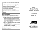
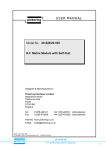
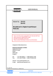
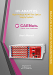
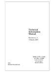
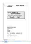
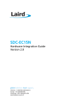
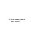
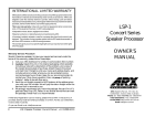
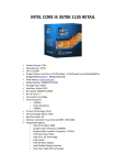
USER MANUAL
pickering
Model No. 10-780
Microwave Switching Modules
Designed & Manufactured by:Pickering Interfaces Limited.
Stephenson Road
Clacton-on-Sea
Essex
CO15 4NL
England
Tel:
Fax:
01255-428141
01255-475058
+44 1255-428141 (International)
+44 1255-475058 (International)
Internet: www.pickering.co.uk
E Mail: [email protected]
Issue 2.00 Jan. 1996
© Copyright (1996) Pickering Interfaces Ltd. All Rights Reserved
pickering
10-780
MICROWAVE SWITCHING MODULES
1
HELP!!!
If you need assistance with your Pickering Interfaces Switching
System: Switching problems, Programming or Integration within your Test
System. – Please ring Pickering Interfaces and ask for “Technical
Support”.
Alternatively you may fax, email or connect to our Internet Web Site.
A full set of operating manuals, application notes and software drivers is
available on CD ROM.
pickering
2
10-780
MICROWAVE SWITCHING MODULES
Contents
Section 1
Microwave Relay Module........................................................................................... 5
Section 2
Programming ............................................................................................................. 9
Section 3
Front Panel Connectors ............................................................................................ 11
Section 4
Electrical, Environmental & Mechanical Specifications ........................................... 13
Section 5
Microwave Relay Data Sheets ................................................................................. 15
pickering
10-780
MICROWAVE SWITCHING MODULES
3
pickering
4
10-780
MICROWAVE SWITCHING MODULES
Section 1
Microwave Relay Module
1.1 Features
• 2 or 4 Changeover Switches per Module
• Switch up to 20W Power at 20GHz
• Direct 50Ω SMA Connection to Switch
• Tree Networks May Be Constructed by Inter-Linking Individual Modules
Relay 1
A
C
B
Relay 2
A
C
B
Relay 3
A
C
B
Relay 4
A
C
B
Pickering Interfaces microwave switching modules offer either 2 or 4 changeover switches per module. Connection is
made direct to the switch using standard SMA female sockets.
Larger networks may easily be constructed by interconnecting individual switches.
1.2 SPDT Microwave Switch
Model 10-780 Changeover Switch General Information
Relay Type
Tesoel
Impedance
Connector Type
Nominal Frequency
50Ω
SMA Jack
20GHz
Operate Release Time
Life
20mS max.
106 operations
10-780-522 2 x SPDT 20GHz Switch
10-780-524 4 x SPDT 20GHz Switch
Table 1.1 10-780 Model Numbers
pickering
10-780
MICROWAVE SWITCHING MODULES
5
Impedance
Maximum Voltage
Maximum Current
On Path Resistance
Off Path Resistance
Differential Thermal Offset
Expected Life
Switching Time
Frequency/GHz
Loss/dB
VSWR
Isolation/dB
<3
< 0.2
< 1.2
> 90
RF Switch Power/W 70
50Ω
100V d.c.
1A
< 200 mW
> 10 10 Ω
< 20µV
> 106 Operations
< 20mS
<8
< 0.3
1.3
> 80
< 12
< 0.4
1.4
> 70
< 20
< 0.5
1.5
> 60
38
30
24
NB. Peak power switching can be well in excess of the
above values but this will affect the switch life. Lower
frequency power is also much higher, e.g. 400W at 0.1GHz,
200W at 0.4GHz.
Table 1.2 10-780 RF and General Specification
Fig 1.1 10-780-524 (4 x SPDT Microwave Relays)
pickering
6
10-780
MICROWAVE SWITCHING MODULES
1.3
Typical RF/Microwave Performance Plots
0 dB
10-780 INSERTION LOSS
-0.1 dB
-0.2 dB
-0.3 dB
-0.4 dB
5GHz
10GHz
15GHz
20GHz
Return Loss
VSWR
Fig 1.2 10-780 Insertion Loss To 20GHz
10-780 VSWR (RETURN LOSS)
1.4
1.3
18dB
1.2
21dB
1.1
26dB
1.0
5GHz
10GHz
15GHz
20GHz
Fig 1.3 10-780 VSWR To 20GHz
10-780 ISOLATION
-70 dB
-80 dB
-90 dB
-100 dB
-110 dB
5GHz
10GHz
15GHz
20GHz
Fig 1.4 10-780 Isolation To 20GHz
pickering
10-780
MICROWAVE SWITCHING MODULES
7
pickering
8
10-780
MICROWAVE SWITCHING MODULES
Section 2
Programming
2.1 Select Module Address
Choose device address (from 0 - 30) using the address select switch on the driver card.The address selected in the
illustration is 22 ( 16 + 4 + 2 = 22).
2.2 10-780 Programming Using the Intelligent GPIB/RS-232 Interface
The 10-780 module is simple to program either by single bit or by word (8 bits).
ARESET a
CLOSE a,b
DELAY t
OPEN a,b
RESET
SIZE s
Clear all outputs on module a
Set bit number b on module a
Force a minimum delay of t milliseconds between two instructions
Clear bit number b on module a
Clear all bits/switches on all modules
This is used to specify the word size: s = 1 for byte, s = 2 for 16 bit word and s = 3 for 32 bit
word (16bit is usually the factory default).
VIEW? a[,b]
View status of module a, can be viewed at any time either as a word or by bit b as a logical value
(1 or0)
WRITE a,c,w Send word w to module a block position cThe module is programmed as an 8 bit output port
using either single bit, byte (8 bits), 16 bit word or 32 bit word:
The module is programmed as an 8 bit output port using either single bit, byte (8 bits), 16 bit word or 32 bit word:
to turn on relay 1 software command close,X,1 is required.
to turn on relay 2 software command close,X,3 is required.
to turn on relay 3 software command close,X,5 is required.
to turn on relay 4 software command close,X,7 is required.
Where X is the module address.
pickering
10
10-780
MICROWAVE SWITCHING MODULES
n
b
examples:
ARESET 8 (clear module 8)
ARESET 8,3 (clear module 8
bank 3)
(send word to
module 5)
c,
READ? a
READ? a,n
w
y
x,
b,
a,
MOPEN a,x,y
MOPEN a,b,x,y
y
x,
b,
a,
MCLOSE MOPEN
Matrix
DELAY t
t
DELAY
Time
Fig 2.1 10-780 Module Instruction Set
CHAN a,c
CHAN a,b,c
CHAN a,b,c,e
e
b,
a,
CHAN
Multiplexer
n
a,
READ?
Digital Input
b,
a,
WRITE
WRITE a,w
WRITE a,b,w
example:
WRITE 5,65264
n
a,
OPEN
CLOSE a,n
example:
CLOSE 5,9 (close relay 9
on module 5)
a,
a,
ARESET a
ARESET a,b
CLOSE
Switch/Digital Output
ARESET
Clear
VIEW?
VIEW? a
VIEW? a,b
VIEW? a,b,c
n
b,
a,
VIEW?
TYPE?
TYPE? a
TYPE? a,b
b
a,
TYPE?
Status
=
=
=
=
=
=
=
=
=
module address
bank number
channel number
multiplexer channel enable
byte mask
bit number
time delay in mS
matrix x coordinate
matrix y coordinate
November 1995
Shaded Areas show allowed
instruction parameter combinations
together with examples
a
b
c
e
m
n
t
x
y
Key:
DIAGNOSTIC? a
a
DIAGNOSTIC?
Errors
Section 3
Front Panel Connectors
1
3
5
7
Fig 3.1 Microwave Module Front Panel with 4 Microwave Relays
(SMA 50Ω Co-Axial Plugs, Connection shown below)
NC
Fig 3.2
C
NO
Microwave Relay Connections
(NC = Normally Closed, NO = Normally Open, C = Common)
pickering
10-780
MICROWAVE SWITCHING MODULES
11
pickering
12
10-780
MICROWAVE SWITCHING MODULES
Section 4
Electrical, Environmental & Mechanical Specifications
Environmental
Operating Temperature 0°C to 50°C.
Storage Temperature -20°C to 75°C.
Humidity 95% non condensing.
Weight Dimensions and Power Requirements
Approx. Weight
410g
Dimensions/mm
3U Eurocard, as specified in DIN 41494
Front Panel Width
60.9
Height
128.5
Overall Length †
189
Power /Current
Consumption
Maximum 5V
Power
12V
600mA
450mA
Minimum 5V
Power
12V
0
† Approx. dimensions. Standard
160mm Eurocard.
Voltage Supplies
Logic Supply 5Vdc ±5%.
Relay Supply 12Vdc ±10%
10-780 Modifications
All modules shipped from April 1993 have been fitted with the relay type described in Sec 1.2. This unit is totally RF
compatible with units shipped prior to this date which were fitted with a Radiall microwave relay. However please note
that the two relay types are not interchangeable, due to minor mechanical differences.
pickering
10-780
MICROWAVE SWITCHING MODULES
13
pickering
14
10-780
MICROWAVE SWITCHING MODULES
Section 5
Microwave Relay Data Sheets
pickering
10-780
MICROWAVE SWITCHING MODULES
15
pickering
16
10-780
MICROWAVE SWITCHING MODULES