1
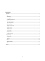
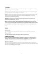
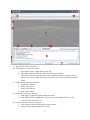
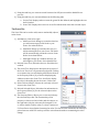
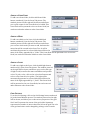
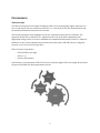
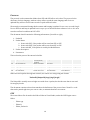
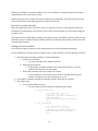
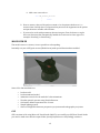
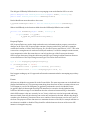
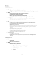
GGE Live Editor User Manual Bjarni Þór Árnason ([email protected]) Pol Jeremias ([email protected]) Game Engine Development – Fall 2008 University of Southern California CONTENTS Concepts.................................................................................................................................................................................... 3 Usage .......................................................................................................................................................................................... 3 Installation .......................................................................................................................................................................... 3 Starting GLE........................................................................................................................................................................ 3 Command line options................................................................................................................................................... 3 The Initial Window.......................................................................................................................................................... 3 The Game Window .......................................................................................................................................................... 5 The Scene Tab.................................................................................................................................................................... 6 Adding a Scene Node ...................................................................................................................................................... 7 Adding a Mesh ................................................................................................................................................................... 7 Adding a Light.................................................................................................................................................................... 7 Grid Settings ....................................................................................................................................................................... 7 GGE Controls ...................................................................................................................................................................... 8 Configuration File ............................................................................................................................................................8 Programming.......................................................................................................................................................................... 9 Architecture........................................................................................................................................................................ 9 Protocol ............................................................................................................................................................................. 10 GGE ...................................................................................................................................................................................... 10 MODELVIEWER ............................................................................................................................................................. 12 GLE ...................................................................................................................................................................................... 12 TO DO ...................................................................................................................................................................................... 15 2 CONCEPTS GGE is short for GamePipe Game Engine, and is USC’s Game Engine. It uses Ogre3D as a renderer, but relies on many other libraries as well. Screen is a concept within GGE that acts almost like a level in a game. A Screen encapsulates game logic and creation, and can have multiple Scenes within it. Scene is a concept within GGE that represent the collection of objects in a game environment. The same Scene can be used by many Screens. Scenes can be defined by hand in C++ code using Ogre3D’s API, or be defined in .scene files. DotScene is a plugin for GGE that reads in .scene files and populates the environment with whatever objects defined in the .scene file. GLE is short for GGE Live Editor, and is the game editor and model viewer for USC’s GGE. It can create .scene files. GLE is basically a control panel on top of GGE. When viewing a model or creating a screen in GLE, the actual GGE executable is launched, and GLE connects to it through a local network connection. All commands to GGE, including all input, are sent through this network socket. USAGE INSTALLATION GLE is distributed as a self extracting Zip file. Execute it and select any folder to extract it to. STARTING GLE GLE can be started by executing GLE.exe in the folder it was extracted to. COMMAND LINE OPTIONS GLE.exe can be launched with command line argument. The argument can either be a path to a .game file, which causes GLE.exe to automatically launch that .game file, or it can be a path to a .mesh file, which causes GLE to automatically open that mesh in the model viewer. THE INITIAL WINDOW This is the initial window that should appear when GLE.exe is launched with no arguments. The major parts of the graphical user interface have been numbered, and each part is explained in detail below. By default, the Model Viewer is opened. 3 1) This is where GGE is rendered. 2) File Operations, from left to right: a. Open Game: Opens a .game file in a new tab. b. Open Mesh: Opens a mesh file in the Model Viewer for display. c. Save Scene: Saves the current Scene to the .scene file defined in the .game file for whatever Screen is loaded. Note that “Save Scene As” can be accesses from the File menu. 3) Camera Setup, from top to bottom: a. Perspective Camera. b. Ortho Top Camera. c. Ortho Front Camera. d. Ortho Side Camera. 4) Grid Setup, from top to bottom: a. Grid Toggle: Toggles the grid visibility on and off. b. Grid Setup: Shows a configuration screen for the grid settings, where you can control the size and color of it. 5) Console Controls, from top to bottom: a. Clear Console: Erases all line in the current console. b. Toggle Console: Shows/hides the console. 4 6) Debug console: This displays all output from the GGE process 7) Status bar: Displays the state of the GGE process 8) ModelViewer Tools, from left to right: a. Bounding Box: Toggles the display of a bounding box aroung the model on and off. b. Lighting: Toggles predefined lighting on and off. c. Wire Frame: Toggles wire frame rendering on and off. 9) ModelViewer Animations, from left to right: a. Play Animation: Plays (or restarts) the animation selected in the combo box. b. Stop Animation: Stops the current animation being played. c. List of animations from the loaded model. 10) ModelViewer Particle Systems. To load a Particle System, select it from the combo box. To unload it, select the topmost blank entry. 11) GGE Process Controls, from left to right: a. Game/Editor Mode: Toggles between game and editor mode. This is not possible to do in the Model Viewer. b. Restart GGE: Restarts the current GGE process completely. All data will be lost. THE GAME WINDOW To load a .game file go to File‐>Open Game and browse to the location of your .game file and hit open. A new tab will now be opened, and a sidebar will pop out from the right that allows you to analyze and edit your current Scene. 5 1) Using this tab bar, you can now switch between the GGE process and the ModelViewer process. 2) Using this tab bar, you can switch between the following tabs: a. Project Tab: Displays what screens the .game file has defined, and highlights the one that is loaded. b. Scene Tab: Displays the scene tree as well as information about the selected object. THE SCENE TAB The Scene Tab can be used to add, remove and modify objects in the Scene. 1) Add Objects, from left to right: a. Add Scene Node: Brings up a window that lets you add a new empty Scene Node to your Scene. See in detail below. b. Add Mesh: Brings up a window that lets you add an existing mesh to your Scene. The mesh will be automatically parented to a new Scene Node. See in detail below. c. Add Light: Brings up a window that lets you add a light to your Scene. See in detail below. 2) Refresh Scene Tree; Refreshes the tree. Should not be needed. 3) The Scene Tree; Displays the hierarchical structure of the Scene Tree as it is represented by Ogre3D. Clicking on an item in the tree will display information about it in the Property Editor (6), as well as displaying any children nodes in the Scene Tree. It will also display the object’s bounding box in the scene, if it has one. 4) Delete Selected Object; Deletes the currently selected object in the Scene Tree. 5) Refresh Selected Object, Refreshes the information in the Property Editor (6) for the selected object in the Scene Tree. 6) The Property Editor; Allows you to view and edit any the selected object has. The functionality of the property is shown on the left side, and the value is on the right side. Only the value may be changed. To do so, either double‐click the value, or select it and press F2. Press Enter when finished entering the value. If it does not exit edit mode, the value you picked was not valid. ESC can be pressed to exit edit mode without committing the value change. 6 ADDING A SCENE NODE To add a new Scene Node, click the Add Scene Node button, numbered (1) in the Scene Tab picture. The window pictured on the right will be shown, and allows you to pick a name for the Scene Node to be added. This Scene Node will be parented to the root Scene Node, but can be moved under whatever other Scene Node. ADDING A MESH To add a new Mesh to the Scene, click the Add Mesh button, numbered (1) in the Scene Tab picture. The window pictured on the right will be shown, and allows you to select which mesh you want to add, and name the entity that will be created in the Scene Tree. It will be automatically parented to a Scene Node that will have the name of the entity, appended by a “_Node”. This Scene Node will be parented to the root Scene Node, but can be moved under whatever other Scene Node. ADDING A LIGHT To add a new Light to the Scene, click the Add Light button, numbered (1) in the Scene Tab picture. The window pictured on the right will be shown, and allows you to select the type of Light to add, as well as the name and diffuse and specular colors. To pick a color, click on the color wheel buttons and select a color from the color picker. The Light will be automatically parented to a Scene Node that will have the name of the Light, appended by a “_Node”. This Scene Node will be parented to the root Scene Node, but can be moved under whatever other Scene Node. GRID SETTINGS To set the Grid Settings, click on the Grid Settings button numbered (4) in the Initial Window picture. The window pictured on the right will be shown, and allows you to edit various properties of the grid. Size X and Z represent the extent of the grid, while Separation represents the number of units in between cells in the grid. The color of the grid and axises can be changed by picking a color from the 7 color picker that is shown when the respective color wheel buttons are pressed. GGE CONTROLS There are two types of controls, Game Controls and Editor Controls. When in Editor Mode, the Editor Controls are used, but when you switch to Game Mode, whatever controls (if any) the game defines take over. The Editor Mode Controls mimic Maya Controls. The Editor Mode Controls are used in the Model Viewer. To rotate about the pivot point, hold left alt and the left mouse button and spin your mouse. To zoom in, hold left alt and scroll the mouse wheel. To move around the scene, hold left alt and the middle mouse button and move the mouse around. To pick an object in the scene from the renderer window, click it with the left mouse button. CONFIGURATION FILE GLE has an XML based configuration file that is loaded on application startup. It is in the same directory as GLE.exe and is named GLE.exe.config. It can control the following settings: AutoStartModelViewProcess: Controls whether or not to automatically load the Model Viewer process on GLE startup. Value can be 1 or 0. HideOutput: Controls whether or not to automatically hide the console output window (numbered (6) in the Initial Window picture). Value can be 1 or 0. CameraRotationSpeed: Controls the sensitivity of the mouse rotation speed in GGE. Value can be any float number, the default value is 0.13. CameraMovementSpeed: Controls the sensitivity of the mouse movement speed in GGE. Value can be any float number, the default value is 0.02. 8 PROGRAMMING ARCHITECTURE The idea for this project was simple, building an editor for an existing game engine written in C++. As it is well known, the user interface written for C++ is not the best one. We decided that C# and the windows framework was perfect for the idea. This decision brought a new challenge, how do we communicate both pieces of software. The approach chosen was to embed the C++ application into a C# panel and communicate both applications using sockets. In order to maintain the communication between C# and C++ stable we decided to create a shared document on internet where the team could add, remove, change the protocol, in our case we used Google Docs. There are three components: ‐ ‐ ‐ GGE Live Editor (C# app) GGE (C ++) Protocol (Document) All of them are very important. GLE is UI to interact with the engine, GGE is the engine by itself, and the protocol defines how both applications interact. GLE Protocol GGE 9 PROTOCOL The protocol is a document that defines how GLE and GGE talk to each other. The protocol is the dictionary for their language, without it they will not speak the same language and if it is not updated they will not use the same words to speak with each other. We strongly recommend sharing this document and keeping it updated. In our case, we used Google Docs to share it and keep it updated but it is up to you to decide the best software to do so. It is now stored as an Excel worksheet in USC’s SVN. The document should contain the following information: (from left to right) 1. PacketID 2. Packet Name a. Starts with GLE_ if the packet will be sent from GLE to GGE b. Starts with GGE_ if the packet will be sent from GGE to GLE c. Starts with MV_ if the packet is used by the ModelViewer 3. Packet description 4. Parameters This is what the protocol document looks like: 14 GLE_SceneNode_Create string name GLE_SceneNode_Del Creates a SceneNode on the active(context) SceneNode Deletes a SceneNode 15 string name 26 GLE_Entity_Create Creates an Entity string name 27 GLE_Entity_Del Deletes an Entity string name 28 GLE_AttachObject Attaches arg1 to arg2 string objToMove GLE.ObjectType string params string objRecieve When we send a packet through the network, we send it as a string using this format: “PacketID||UniqueID||Arg1||Arg2||ArgN;;” The UniqueID is actually not used right now aside from 1 packet, but the idea was that it was used for integrity checks. The document contains a sheet that translates the definition of the protocol into C# and C++ code that can be pasted right into your source code, to maintain absolute correctness. GGE We created three files located in the Editor folder in Visual Studio, under the GGE Engine source folder: ‐ ‐ ‐ Editor.cpp Editor.h Editor_Packets.h 10 Editor.cpp and Editor.h contain the Editor class. It is in charge of communicating with GLE, parse any packet that arrive and execute them. Editor_Packets.h is just a header file with the definition of the packets extracted directly from the Protocol document so that both applications share the same IDs. How does it works internally When the application starts, the editor creates a connection, if you are executing the application through GLE what happens is that GLE becomes client of GGE and then the conversation using the protocol starts. The main function in GGE (Editor module) is the packet parser called Editor_Parser(). This function basically uses the constants defined in Editor_Packets.h to identify which packet is and execute the correspondent function. Adding new functionalities Once an idea is approved and correctly designed proceed to the following methodology. For this example we will develop an example of how to add a packet to activate shadows from GLE. 1. Open the shared document with the constant definitions. a. Add the new identifier i. For instance define: GLE_Shadows_Activate b. Add a unique packet ID i. Find a unique available packet ID, if the shared document is correctly updated this should not be a problem c. Define the parameters that the packet will contain. i. In the example, we can assume we just want to activate/deactivate the shadows. So that, we just need an integer as 1 or 0. 2. Open Editor_Packets.h and add the identifier and the unique ID as constants. 3. Open Editor.cpp a. Go to function Editor_Parser() i. Go to the main switch in charge of identifying the packets case GLE_SceneNode_Create: { Ogre::String name = tokens[2]; // Create a scene node m_pRenderer->_getCurrentSceneManager()-> getRootSceneNode()-> createChildSceneNode(Ogre::String(name)); break; } case GLE_SceneNode_Del: { Ogre::String name = tokens[2]; // Destroy the node by its name m_pRenderer->_getCurrentSceneManager()-> destroySceneNode(Ogre::String(name)); break; } 11 ii. Add a new case such as : case GLE_Shadows_Activate: { break; } b. Now we want to detect if the packet contain a 0 to deactivate shadows or 1 to activate them. Luckily there is a function that parses all the arguments in the packet and put them in a variable called Tokens. c. If you need to work with parameters that are integers, floats, booleans or tuples there are functions that automatically handle the conversion to these types. For example: ParseInt() or ParseFloat() MODELVIEWER The model viewer is a viewer; it is not possible to edit anything. Internally it is just a GGE game screen (BlankScreen) with special functionalities enabled. Some of the functionalities are: • • • • • • • Load a model. Load an animated model. Animation controls for the models if it has animations. Visualize particle systems using ParticleUniverse. Grid with a default separation size of 1 unit. Simple lighting system. Camera configurable between perspective projection and orthographic projection. GLE GLE is written in C# using Microsoft Visual Studio 2008. To successfully run GLE from Visual Studio you need to make sure that the output folder (usually bin/Release or bin/Debug) contains a 12 ModelViewer.game file that contains the path to the GGE ModelViewer executable that GLE will use. The default one assumes the USC SVN folder structure to be intact. Data Structures DataStructures.cs contains small simple classes that serve no purpose but to pass on information. It also contains all Enumerations (Enums) that define various things, such as the types of Objects recognized, and all protocol packets supported. GGE The GGE Class (defined in GGE.cs) is a wrapper around a GGE process. Each GGE instance (of the class) corresponds to 1 GGE process (executable). It handles starting and stopping the GGE executable, as well as encapsulating all interaction with GGECommm (see below) from the programmer. All data that needs to be sent to the GGE process goes through a “Protocol function” defined in this class. These functions have the exact same name as the protocol packets as well as the same arguments as defined in the protocol document. This example shows how the GLE_SceneNode_Create protocol packet is implemented: public void GLE_SceneNode_Create(string name) { GGE_GenericCommand((int)GLE.EditorProtocol.GLE_SceneNode_Create, name); } So in order to create a new SceneNode in GGE, all you need to do is: m_ggeGame.GLE_SceneNode_Create(“myNode”); GGE_GenericCommand is a function that takes in any number of arguments and converts them into a GGE_Message, and then queues that message to be sent by GGEComm. GGEComm The GGEComm class (defined in GGEComm.cs) is the network communication implementation of the program. The GGEComm class handles everything network/socket related. Every GGE instance has 1 GGEComm instance. It handles setting up a connection to GGE, receiving messages and sending them. Prety much everything in this class is threaded. There is a separate thread for polling GGE for connection, another thread for handling incoming messages, and a separate thread for EVERY outgoing message. Events Since GGEComm is all threaded, whenever something needs to be done in the GUI because of a packet was received, it needs to be done though events, because the GUI in C# is not thread safe. One simple example is the handling the GGE_Ready packet. When the packet is received by GGEComm, it calls the HandleMessage function in the GGE instance. We now know that we want to notify the GUI that the GGE process is ready, so we must invoke an event like this (here Parent is a reference to the MainForm): Parent.BeginInvoke(GGEReadyCallBack, this, new EventArgs()); 13 The delegate GGEReadyCallBack and its corresponging event are defined in GGE.cs as such: public delegate void GGEReadyEventHandler(object sender, EventArgs e); public event GGEReadyEventHandler GGEReadyCallBack; But the MainForm must subscribe to the event: m_ggeGame.GGEReadyCallBack += new GGE.GGEReadyEventHandler(OnGGEReady); Where OnGGEReady is the function called when the GGEReadyCallBack even is called: private void OnGGEReady(object sender, EventArgs e) { if ((GGE)sender == m_ggeMV) m_ggeMV.MV_GetListParticleSystems(); } PropertyTuples GLE_PropertyTuples are used to both send and receive information about property retrievals or changes on an object. GLE_PropertyTuple contains a Property and a Value, and can for example contain the Position on X axis, where Property_Pos_X is the Property and Value is “13.37”. The value is stored as a string because it can be more than just numbers, it could for example contain a name, or an enumeration value. But even then, we can look up the type of the Property in the static GLE.PropType dictionary. Using this dictionary and C#’s type casting/creation functions allows us create an instance of the object using its actual type. This can be done as follows: Type T = GGE.PropTypes[propTuple.Property]; if (T.BaseType.Name == "Enum") valueCell.Value = System.Enum.Parse(T, pair.Value); else valueCell.Value = Convert.ChangeType(pair.Value, T); But I suggest reading up on C#’s type and reflection documentation before attempting any trickery with it. Forms All forms are defined in a separate file in the Forms folder. The most important one is the MainForm (defined in MainForm.cs). The most important thing about that form is that it contains references to 2 GGE instances, one for the GGE game (m_ggeGame) and another one for the Model Viewer (m_ggeMV). Both of them might not always be initialized so it must be checked whether they reference null before usage or not. MainForm also has a function GetActiveGGE() to determine which GGE instance is the one currently “in use”, that is, which one is in the foreground and being interacted with. Even still, this function can return null, and must be checked. Another key thing to consider is the Evaluate*() functions. There are a number of these functions, one for each “part” of the form. The purpose of these functions is to maintain the state of the GUI, for example whether or not a button is enabled or disabled. They should be called whenever the state of the active GGE instance is changed in any way. 14 TO DO From the final review: • • • • • Core o Dynamic Screen loading by the screen’s name. o Engine stats displayed on screen with a keypress (min/max fps, triangle count, etc). Editor o Press F for focusing the camera on the selected object. o Control generic cameras in the editor. o Mouse right button for smooth zoom like in Maya. o Add a billboard (frustum maybe?) to visualize lights in editor mode Model Viewer o Dynamic resource group initialization on the folder in which the model is. o Auto fit model to scrren with the ortho cameras. GLE o Combo box for the light type (and all enumerations) in the property editor. o Change the name of the configuration file. o Hotkeys for functionality. o Automatically scroll to an object in the scene tree when it is picked in the scene o Translation, rotation and scale by interacting with the object in the renderer window. o TabIndexes in the property editor. o Commit changes in the name, property editor. o Modify ambient light and background color. Known problems o Picking after reparenting. o Grid settings are not displayed correctly in the GUI when switching between Screens. From the milestones: • • UI o Undo/Redo o Resource management tab CORE o Different types of GameObjects Dynamic objects Character functionality expanded for physics Particle systems Keyframe objects Vehicles 15