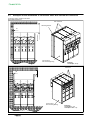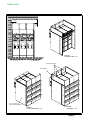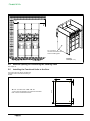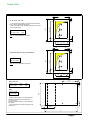
1
Secondary Distribution Switchgear
Fluokit M24+
Air insulated switchgear
Instructions
Civil Engineering Structures
Fluokit M24+
Contents
1
Schneider Electric at your service . . . . . . . . . . . . . . . . . . .
1
1.1
1.2
1.3
1.4
1.5
Particular instructions for operations and interventions . . . . . . . . . . . . . . . . . . .
Protection equipments . . . . . . . . . . . . . . . . . . . . . . . . . . . . . . . . . . . . . . . . . . . . . .
Symbols of information . . . . . . . . . . . . . . . . . . . . . . . . . . . . . . . . . . . . . . . . . . . . .
Symbols and important safety informations . . . . . . . . . . . . . . . . . . . . . . . . . . . .
Contacts . . . . . . . . . . . . . . . . . . . . . . . . . . . . . . . . . . . . . . . . . . . . . . . . . . . . . . . . .
1
1
1
1
1
2
With regards to this User Manual . . . . . . . . . . . . . . . . . . . .
2
2.1
2.2
2.3
2.4
Use of this User Manual . . . . . . . . . . . . . . . . . . . . . . . . . . . . . . . . . . . . . . . . . . . .
Definition of the substations . . . . . . . . . . . . . . . . . . . . . . . . . . . . . . . . . . . . . . . . .
Access to the substation . . . . . . . . . . . . . . . . . . . . . . . . . . . . . . . . . . . . . . . . . . . .
Other technical notices to be consulted . . . . . . . . . . . . . . . . . . . . . . . . . . . . . . . .
2
2
2
2
3
Dimensions of the Functional Units . . . . . . . . . . . . . . . . . .
3
3.1
3.2
3.3
Dimensions and approximate weight of the Functional Units . . . . . . . . . . . . . .
Dimensions of an IS - PF - PFA or TM Functional Unit . . . . . . . . . . . . . . . . . . .
Dimensions of a PGB or PGC Functional Unit . . . . . . . . . . . . . . . . . . . . . . . . . .
3
4
4
4
General rules for the installation of Functional Units . .
5
4.1
Reminder concerning normal installation and service conditions
(in accordance with IEC 62271-1) . . . . . . . . . . . . . . . . . . . . . . . . . . . . . . . . . . . .
* Permissible ambient temperature . . . . . . . . . . . . . . . . . . . . . . . . . . . . . . . . . . .
* Installation altitude . . . . . . . . . . . . . . . . . . . . . . . . . . . . . . . . . . . . . . . . . . . . . . . .
* Atmospheric pollution . . . . . . . . . . . . . . . . . . . . . . . . . . . . . . . . . . . . . . . . . . . . .
* Permissible atmospheric humidity level . . . . . . . . . . . . . . . . . . . . . . . . . . . . . .
Substation installation requirements . . . . . . . . . . . . . . . . . . . . . . . . . . . . . . . . . .
Installation of the switchboard . . . . . . . . . . . . . . . . . . . . . . . . . . . . . . . . . . . . . . .
Precautions for the installation of a Fluokit M24+ switchboard . . . . . . . . . . . . .
5
5
5
5
5
5
5
5
5
Installing Functional Units . . . . . . . . . . . . . . . . . . . . . . . . . .
6
5.1
5.2
5.3
5.4
5.5
5.6
5.7
Example of a free installation switchboard, without internal arc withstand . . . .
Switchboard back-to-back against a wall or not, with internal arc withstand . .
Examples of the installation of Functional Units with internal arc deflectors . .
Reserve opening for connecting the earthing cable . . . . . . . . . . . . . . . . . . . . . .
Installing the Functional Units to the floor . . . . . . . . . . . . . . . . . . . . . . . . . . . . . .
Geometry of the cable trough . . . . . . . . . . . . . . . . . . . . . . . . . . . . . . . . . . . . . . . .
Altitude of the connecting points in relation to the cable flanges (other than
mounting base) . . . . . . . . . . . . . . . . . . . . . . . . . . . . . . . . . . . . . . . . . . . . . . . . . . .
6
7
8
10
10
13
14
6
The civil engineering structure . . . . . . . . . . . . . . . . . . . . . .
15
6.1
6.2
Geometry . . . . . . . . . . . . . . . . . . . . . . . . . . . . . . . . . . . . . . . . . . . . . . . . . . . . . . . .
Special cases . . . . . . . . . . . . . . . . . . . . . . . . . . . . . . . . . . . . . . . . . . . . . . . . . . . . .
15
15
7
Civil Engineering without a metal section . . . . . . . . . . . .
16
7.1
7.2
7.3
7.4
Example of the installation of a switchboard in a conventional building . . . . . .
Work on the Civil Engineering structure . . . . . . . . . . . . . . . . . . . . . . . . . . . . . . .
Advice that is appropriate for the various types of cable troughs . . . . . . . . . . .
Layout on a type 2 cable trough, with width of more than 50cm . . . . . . . . . . . .
16
16
16
16
8
Civil Engineering structure with open metal sections .
17
8.1
8.2
Mounting on metal sections called `irons' . . . . . . . . . . . . . . . . . . . . . . . . . . . . . .
Work on the Civil Engineering structure . . . . . . . . . . . . . . . . . . . . . . . . . . . . . . .
Preparation of the sections . . . . . . . . . . . . . . . . . . . . . . . . . . . . . . . . . . . . . . . . . .
Levelling the profile sections . . . . . . . . . . . . . . . . . . . . . . . . . . . . . . . . . . . . . . . . .
Reserve opening at the extremity of each rail . . . . . . . . . . . . . . . . . . . . . . . . . . .
Pouring the cement top coat . . . . . . . . . . . . . . . . . . . . . . . . . . . . . . . . . . . . . . . . .
Case of a type 2 cable trough . . . . . . . . . . . . . . . . . . . . . . . . . . . . . . . . . . . . . . . .
17
17
17
17
18
18
18
9
Civil Engineering structure with metal sections on
a slab . . . . . . . . . . . . . . . . . . . . . . . . . . . . . . . . . . . . . . . . . . . . . .
19
9.1
9.2
9.3
9.4
9.5
Mounting of metal profile sections on slabs . . . . . . . . . . . . . . . . . . . . . . . . . . . .
Preparation of the frame in profile sections . . . . . . . . . . . . . . . . . . . . . . . . . . . . .
Installation of the frame . . . . . . . . . . . . . . . . . . . . . . . . . . . . . . . . . . . . . . . . . . . . .
Pouring the cement top coat . . . . . . . . . . . . . . . . . . . . . . . . . . . . . . . . . . . . . . . . .
Installation of the switchboard at height, on a frame . . . . . . . . . . . . . . . . . . . . .
19
19
19
20
20
10
Connecting the switchboard to earth . . . . . . . . . . . . . . . .
21
10.1
Reserve opening for connecting the earthing circuit . . . . . . . . . . . . . . . . . . . . .
21
4.2
4.3
4.4
AMTNoT093-02 revision: 09
i
Fluokit M24+
ii
11
Last checks before installation of the Functional Units
22
11.1
11.2
Reading of the surface evenness . . . . . . . . . . . . . . . . . . . . . . . . . . . . . . . . . . . . .
Layout of the Functional Units . . . . . . . . . . . . . . . . . . . . . . . . . . . . . . . . . . . . . . .
22
22
12
Notes . . . . . . . . . . . . . . . . . . . . . . . . . . . . . . . . . . . . . . . . . . . . . .
23
AMTNoT093-02 revision: 09
Fluokit M24+
1 Schneider Electric at your
service
© - Schneider Electric - 2011. Schneider
Electric, the Schneider Electric logo and their
figurative forms are Schneider Electric
registered trademarks. The other brand
names mentioned within this document,
whether they be copyright or not, belong to
their respective holders.
Schneider Electric request the carefully
reading of the following instructions in order
to familiarize yourself with the product in this
document before trying to install, operation,
put into service or conduct the maintenance
on it.
Our products are fully quality controlled and
tested at the factory in accordance with the
standards and regulations currently in force.
The correct functioning and lifespan of the
product depend on respecting the installation,
commissioning and exploitation instructions
found in this manual. Not respecting these
instructions is likely to invalidate any
guarantee.
Local safety requirements which are in
accordance with these instructions,
especially those regarding the safety of
product operators and other site workers,
must be observed.
Schneider Electric declines any responsibility
for the following points:
- the non respect of the recommendations in
this manual which make reference to the
international regulations in force.
- the non respect of the instructions by the
suppliers of cables and connection
accessories during installation and fitting
operations,
- possible aggressive climatic conditions
(humidity, pollution, etc.) acting in the
immediate environment of the materials that
are neither suitably adapted nor protected for
these effects.
1.1 Particular instructions for operations and interventions
This user manual does not list the locking-out
procedures that must be applied. The
interventions described are carried out on
de-energized equipment (in the course of
being installed) or locked out (non
operational).
1.2
1.3
A qualified person is one who has the skills
and knowledge related to the construction,
installation and operation of electrical
equipment and has received safety training to
recognize and avoid the hazards involved.
Except when it is imposed, the wearing of the
gloves has been voluntarily limited in this
manual so as to have clear visuals of the
hands and operations described.
Symbols of information
06
Code for a product recommended
and marketed by Schneider Electric
21
Nm
Tightening torque value
Example: 21 Nm
10
Mark corresponding to a key
Symbols and important safety informations
The following special messages may appear
throughout this bulletin or on the equipment to
warn of potential hazards or to call attention
to information that clarifies or simplifies a
procedure.
DANGER
DANGER indicates an imminently hazardous
situation which, if not avoided, will result in
death or serious injury.
1.5
All operations must be completed once
started.
The durations (for completing the operations
mentioned) given in the maintenance tables
are purely an indication and depend on
on-site conditions.
Protection equipments
Only qualified and accredited people can
operate on our products. They must be
equipped with all the correct protective
equipment required for the task being
performed.
1.4
Whilst commissioning and operating the
product all general safety instructions for
electrical applications (protective gloves,
insulating stool, etc.) must be respected, this
in addition to the standard operating
instructions.
WARNING
WARNING indicates a potentially hazardous
situation which, if not avoided, can result in
death or serious injury.
NOTICE
NOTICE is used to address practices not
related to physical injury. The safety alert
symbol shall not be used with this signal
word.
CAUTION
CAUTION indicates a potentially hazardous
situation which, if not avoided, can result in
minor or moderate injury.
Contacts
Group Schneider Electric service centers are
there for:
J
J
J
J
J
J
Engineering and technical assistance
Commissioning
Training
Preventive and corrective maintenance
Spare parts
Adaptation work
Schneider Electric Energy France
35 rue Joseph Monier - CS 30323
F-92506 Rueil-Malmaison Cedex
www.schneider-electric.com
AMTNoT093-02 revision: 09
1
Fluokit M24+
2.1
2 With regards to this User Manual
Use of this User Manual
This User Manual describes the works or
arrangements necessary for the installation of
a HVA switchboard of the Fluokit M24+ type.
2.2
Definition of the substations
Amongst substations that are prefabricated or
built outdoors, walk-in substations can reach,
or even exceed 2.5 m in height. They allow
operating personnel to penetrate into the
substation and work in them sheltered from
bad weather.
2.3
J
2
The indoor substations with “prefabricated
metal-clad bays” are installed in areas that
the User reserves in one of the buildings in
the factory, or in a building specially built for
this purpose in the case of transformer
substations for HVA distribution networks.
Access to the substation
Substation access must remain free at all
times and under any circumstances. It is
therefore generally installed on the side of the
road.
2.4
In the cases of replacement of the Fluokit
M24 switchboard or substation renovation, a
specific design study must be carried out.
Passages must be designed to permit easy
maintenance for all of the substation's
elements (circuit breaker, transformer, etc.)
Other technical notices to be consulted
AMTNoT090-02
Fluokit M24+
Installation - Commissioning - Operation - Maintenance
AMTNoT093-02 revision: 09
Fluokit M24+
3.1
3 Dimensions of the Functional
Units
Dimensions and approximate weight of the Functional Units
Functional Units
IS - PFA
TM
PBB or
PGC
PGB - PGC
1,250A
Width (mm)
375
500
375
500
750
875
1125
1250
1000
Overall Depth (mm)
1072
1072
1072
1072
1110*
1110*
1110*
1110*
1110
standard
1610
1610
1610
1610
1610
1610
1610
1610
1610
with deflector or LV box on the roof
1950
1950
1950
1950
1950
1950
1950
1950
1950
Manoeuvering space at
the front (mm)
800
800
800
800
1000
1000
1000
1000
1000
Approximate weight (kg)
115
125
195
210
410
460
510
610
600
Height (mm)
* Withdrawable Functional Unit in size 1,120 mm
AMTNoT093-02 revision: 09
3
Fluokit M24+
3.2
Dimensions of an IS - PF - PFA or TM Functional Unit
850
1950
1550
1610
Deflector Option
375
or 500
1072 (overall)
3.3
Dimensions of a PGB or PGC Functional Unit
850
1950
1550
1610
Deflector Option
750, 875
or 1125 (withdrawable)
1110 (overall)
4
AMTNoT093-02 revision: 09
Fluokit M24+
4.1
4 General rules for the installation
of Functional Units
Reminder concerning normal installation and service conditions (in accordance
with IEC 62271-1)
* Permissible ambient temperature
The ambient air temperature should be
comprised between - 5°C and + 40° C.
The mean measured value for a 24 hour
period must not exceed 35° C.
* Installation altitude
Items of HV equipment are defined in
accordance with European Standards and
can be used up to an altitude of 1,000 m.
Beyond this, account must be taken of the
decrease in dielectric withstand.
For these specific cases, contact the
Schneider Electric Sales Department.
* Atmospheric pollution
The ambient air must not contain any dust
particles, fumes or smoke, corrosive or
flammable gases, vapours or salts.
* Permissible atmospheric humidity level
The average atmospheric relative humidity
level measured over a 24-hour period must
not exceed 95%.
The average water vapour pressure over a
period of 24 hours must not exceed 22 mbar.
The average atmospheric relative humidity
value measured over a period of one month
must not exceed 90 %.
The average water vapour pressure over a
period of one month must not exceed
18 mbar.
4.2
Water, snow, or animal salts must not be able
to penetrate.
Also prevent any penetration by small
animals such as rodents, snakes, lizards, etc.
especially in tropical areas.
The room must be equipped with
standardised high level and low level
ventilation.
Installation of the switchboard
The positioning of the Functional Units is
primordial for:
- minimum spaces at the front (walk-in
corridor for manoeuvering), at the rear and on
each side of the switchboard. Certain
passages must be sufficient for free
movement and execution of operation and
maintenance manoeuvres,
- leave the room's access door free,
- take all measures to prevent all incidence of
climatic conditions (humidity, pollution, etc.).
4.4
Whenever the humidity level is higher than
90 %, we recommend that you take
appropriate corrective measures. For any
assistance or advice, contact the Schneider
Electric After-Sales department.
Substation installation requirements
The substation must be sheltered from
flooding and any infiltrations. No ducts of any
kind must pass through the substation's
immediate environment without special
protection (sheaths or ducts).
4.3
Condensation may appear in case of any
sharp variation in temperature, due to
excessive ventilation, a high atmospheric
humidity level or the presence of hot air. This
condensation can be avoided by an
appropriate lay-out of the room or of the
building (suitably adapted ventilation, air
driers, heating etc.).
The delimitation of the civil engineering layout
depends on the type and quantity of materials
to be installed refer to the following chapters).
Precautions for the installation of a Fluokit M24+ switchboard
This equipment is designed to be installed
back-to-back against a wall. Nevertheless, if
the room's architecture does not permit this
type of installation, other options exist in
order to meet the requirements of Standard
IEC62271-200 FLR (rear access, internal
arcing etc.)
Respect the imposed distances
(see chapter 5).
AMTNoT093-02 revision: 09
Ensure that the envisaged layout does not
disturb access to the room. It must be
possible to enter or withdraw items of
equipment without any handling difficulty.
Do not place Functional Units below any
ventilation grilles, air vents, or air conditioning
grilles or in the immediate proximity of glass
tile panels in direct contact with the outside.
The switchboard must not be exposed to any
solar radiation. A direct exposure can lead to
excessive overheating of the low voltage
racks.
Cable troughs and ducts must be blocked up
to avoid:
- any draughts of air below the Functional
Units,
- any rise in humidity or pollution coming from
below ground.
5
Fluokit M24+
h
Box option
h1
Example of a free installation switchboard, without internal arc withstand
h2
5.1
5 Installing Functional Units
Space for
manoeuvering
d3
d1
d2
d 2 (mm)
Distance
d1 (mm)
Normal
100
Recommended
250
6
d 3 (mm)
IS-PFA-TM
PGB - PGC
IS-PFA-TM
PGB - PGC
1972
2122
800
1000
2360
1000
h (mm)
h1 (mm)
h2 (mm)
2100
490
150
2150
590
260
AMTNoT093-02 revision: 09
Fluokit M24+
Switchboard back-to-back against a wall or not, with internal arc withstand
h2
Box
option
20 kA option
h
400 mm
ÏÏÏÏÏÏÏÏÏÏ
ÏÏÏÏÏÏÏÏÏÏ
ÏÏÏÏÏÏÏÏÏÏ
ÏÏÏÏÏÏÏÏÏÏ
ÏÏÏÏÏÏÏÏÏÏ
ÉÉ
ÏÏÏÏÏÏÏÏÏÏ
ÉÉ
h1
5.2
Space for
manoeuvering
d3
d1
d2
d 2 (mm)
Distances
d1 (mm)
d 3 (mm)
IS-PFA-TM
PGB - PGC
IS-PFA-TM
PGB - PGC
h (mm)
h1 (mm)
h2 (mm)
12.5 kA
AF (0.7 s) (HN64S41)
100
1972
2210
800
1000
Min. 2100
490
150
16 kA
AF or AFL (1 s)
100
1972
2210
800
1000
Min. 2150
540
200
20 kA
AF or AFL (1 s)
250
2122
2360
800
1000
Min. 2150
540
200
12.5 kA or 16 kA
AFLR (1 s)
Free
Free
Free
800
1000
Min. 2150
540
200
20 kA
AFLR (1 s)
Free
Free
Free
800
1000
Min. 2150
540
200
25 kA
AF (1 s)
250
2372
2610
800
1000
Min. 2150
540
200
AMTNoT093-02 revision: 09
7
Fluokit M24+
5.3
Examples of the installation of Functional Units with internal arc deflectors
For all other cases, consult the Schneider
ElectricSales Department.
Rear deflectors
Wall fixing bracket
490 mm min.
20
Far-end panel
with rear strengthening
Example:
12.5 kA (AF – 0.7 s)
Deflectors
200
60
Far-end panel
with rear strengthening
8
Examples:
12.5 kA (AFL - 1 s)
16 kA (AF or AFL - 1 s)
AMTNoT093-02 revision: 09
Fluokit M24+
200
60
Example:
20 kA (AF or AFL - 1 s)
Front arc deflectors
Side deflector
Far - end panel
with rear strengthening
Example:
12.5 and 16 kA (AFLR - 1 s)
AMTNoT093-02 revision: 09
Example:
20 kA (AFLR – 1 s)
9
Fluokit M24+
200
140
Far - end panel
with rear reinforcement and
internal insulating plate
Example:
25 kA (AF – 1 s)
5.4
Reserve opening for connecting the earthing cable
See chapter 10.
5.5
Installing the Functional Units to the floor
The routes, seen from above, represent the
perimeter of the Functional Unit bearing on
the floor.
18
60
18
70
- 4 fixing points are possible in the angles with H M12x30
bolts + 30 mm Ø external flat washer.
850
TM - LC - LT - LVT - LCT - LCVT - SP - LP
375 or 500 mm
10
AMTNoT093-02 revision: 09
Fluokit M24+
18
18
100
85
N.B.: 640 mm if installation using PGC
C1
60
Ä
Ä
Ä
Ä
Ä
70
500
180
190
375
C1 (mm) 117.5
(550) 640
C (mm)
850
- 4 fixing points are possible in the angles with H M12x30
bolts + 30 mm Ø external flat washer.
- width of the cable trough varaible depending on the depth
of the Functional Unit
190
IS - PF - PFA - LST - LD
C1
70
C
18
18
220
850
C3 (mm) 164.5
640
C2 (mm) 195.5
60
100
100
N.B.: 640 mm if installation using PGC
Ä
Ä
Ä
Ä
70
220
IS with assembly of 3 current transformers
C3
C2
70
500
C2
18
C (mm)
750
875
1125
C2 (mm) 339
464
339
60
PGB - PGc + LR
PBB
1000
- 4 fixing points possible in the right hand part,
spaced out depending on the width of the
Functional Unit.
Fixing by H M12x30 bolts + 30 mm Ø external
flat washer.
- The circuit breaker's axes are represented by
dotted lines.
70
C2 (mm) 464
850
C (mm)
65
245
C
AMTNoT093-02 revision: 09
11
Fluokit M24+
18
C2
PGC
464
464
C3 (mm) 117.5
195.5
195.5
C4 (mm) 117.5
164.5
164.5
60
Ä
70
C2 (mm) 339
220
875
100
3TC + 3TP
875
100
3TC
750
640
850
3TC
C (mm)
Ä
Ä
Ä
220
- 4 fixing points possible in the right hand part,
spaced out depending on the width of the
Functional Unit. Fixing by H M12x30 bolts
+ 30 mm Ø external flat washer.
- The circuit breaker's axes are represented by
dotted lines.
65
245
C4
C3
70
C
C2
375
1250
464
C3 (mm) 117.5
195.5
C4 (mm) 117.5
164.5
65
C4
245
70
220
220
640
850
100
1125
C2 (mm) 339
100
C (mm)
60
Ä
Ä
Ä
Ä
Ä
PGC
- 6 fixing points possible in the right hand
part, spaced out depending on the width of
the Functional Unit. Fixing by H M12x30 bolts
+ 30 mm Ø external flat washer.
- The circuit breaker's axes are represented
by dotted lines.
18
C3
70
C
C2
375
18
PGC - assembly of 2 cables per phase
220
60
ÄÄÄ
ÄÄÄ
ÄÄÄ
ÄÄÄ
C3 (mm) 100
100
C4 (mm) 164.5
100
C5 (mm) 95.5
65
C4
245
C5
C3
70
220
640
C2 (mm) 464
850
- 6 fixing points possible in the right hand part,
spaced out depending on the width of the
Functional Unit. Fixing by H M12x30 bolts + 30
mm Ø external flat washer.
- The circuit breaker's axes are represented by
dotted lines.
70
1250
12
AMTNoT093-02 revision: 09
Fluokit M24+
18
ÄÄ
Ä
ÄÄÄ
ÄÄÄ
ÄÄ
Ä
ÄÄÄ
190
100
70
85
850
N.B.: 640 mm installation using PGC
550 (640)
190
- 4 fixing points are possible in the angles by
H M12x30 bolts + 30 mm Ø external flat washer.
60
IS - LST - LD - assembly of 2 cables per phase
18
164.5
95.5
100
70
500
5.6
Geometry of the cable trough
The depth of the cable trough depends on the
cross-section of the HV cables.
Generally this depth [P] is equal to (generally
higher) than the bend radius of the cables [R].
The length of the cable is calculated as a
function of the altitude [A] of the connecting
point.
NOTICE
Refer to the cable manufacturer's
recommendations (ambient temperature,
etc.).
Cable sections
(mm2)
Depth for a single pole cable*
P (mm)
Depth for a three-pole cable*
P (mm)
50
450
600
95
450
700
150
600
800
240
600
900
300
600
-
400
600
-
* depth except assembly of tank. In the case
of assembly of tank, Deph = P + tank height.
AMTNoT093-02 revision: 09
13
Fluokit M24+
Assembly of tank
Height: 350mm
Standard assembly
e
d
350
e
P
P
R
Functional Unit
Distance from the edge [d] (mm)
Distance between phases [e] (mm)
IS - LST
185
190
PF-PFA
185
190
PGC
200
220
Altitude of the connecting points in relation to the cable flanges (other than
mounting base)
Functional Unit
A (mm)
A1 (mm)
IS - LST
646.5
908
PF-PFA
370
-
PGC
340
-
14
A
A
A1
A
5.7
R
AMTNoT093-02 revision: 09
Fluokit M24+
6.1
6 The civil engineering structure
Geometry
Generally, HV cables penetrate into the room
underground. They are routed along a cable
trough or trench or through floor openings.
These openings are to be calculated and
carried out at the same time as the
installation of the equipment to the floor.
GROUND FLOOR SUBSTATION
ÎÎÎÎÎÎÎÎÎÎÎÎ
ÎÎÎÎÎÎÎÎÎÎÎÎ
ÎÎÎÎÎÎÎÎÎÎÎÎ
ÎÎÎÎÎÎÎÎÎÎÎÎ
ÎÎÎÎÎÎÎÎÎÎÎÎ
ÎÎÎÎÎÎÎÎÎÎÎÎ
ÎÎÎÎÎÎÎÎÎÎÎÎ
Type 1: Cable trough at the
front or rear of the Functional
Units
ÎÎÎÎÎÎÎÎÎÎÎÎ
ÎÎÎÎÎÎÎÎÎÎÎÎ
ÎÎÎÎÎÎÎÎÎÎÎÎ
ÎÎÎÎÎÎÎÎÎÎÎÎ
ÎÎÎÎÎÎÎÎÎÎÎÎ
ÎÎÎÎÎÎÎÎÎÎÎÎ
ÎÎÎÎÎÎÎÎÎÎÎÎ
Type 2: Lateral cable trough
under the Functional Units
UPPER FLOOR SUBSTATION
Type 3: Floor openings under
the Functional Units
6.2
Special cases
Within the scope of renovation work, if the
nature of the floor does not allow for works to
be carried out or if the incoming of the cables
is overhead, then the Functional Units can be
raised.
In this case a mounting base is added to the
lower part of each Functional Unit in order to
facilitate the penetration of the cable and
respect the bend radius necessary for its
connection.
AMTNoT093-02 revision: 09
15
Fluokit M24+
7.1
7 Civil Engineering without a metal
section
Example of the installation of a switchboard in a conventional building
ÑÑÑÑÑÑÑÑÑÑÑÑÑÑÑÑÑÑÑÑÑÑÑÑÑÑÑÑÑÑÑÑÑ
ÑÑÑÑÑÑÑÑÑÑÑÑÑÑÑÑÑÑÑÑÑÑÑÑÑÑÑÑÑÑÑÑÑ
ÄÄ
Ä
ÄÄ
Ä
ÑÑÑÑÑÑÑÑÑÑÑÑÑÑÑÑÑÑÑÑÑÑÑÑÑÑÑÑÑÑÑÑÑ
ÑÑÑÑÑÑÑÑÑÑÑÑÑÑÑÑÑÑÑÑÑÑÑÑÑÑÑÑÑÑÑÑÑ
ÄÄ
Ä
ÄÄ
Ä
ÑÑÑÑÑÑÑÑÑÑÑÑÑÑÑÑÑÑÑÑÑÑÑÑÑÑÑÑÑÑÑÑÑ
ÄÄ
Ä
ÄÄ
Ä
ÄÄ
Ä
ÄÄ
Ä
É
ÑÑÑÑÑÑÑÑÑÑÑÑÑÑÑÑÑÑÑÑÑÑÑÑÑÑÑÑÑÑÑÑÑ
ÑÑÑÑÑÑÑÑÑÑÑÑÑÑÑÑÑÑÑÑÑÑÑÑÑÑÑÑÑÑÑÑÑ
É
ÑÑÑÑÑÑÑÑÑÑÑÑÑÑÑÑÑÑÑÑÑÑÑÑÑÑÑÑÑÑÑÑÑ
ÑÑÑÑÑÑÑÑÑÑÑÑÑÑÑÑÑÑÑÑÑÑÑÑÑÑÑÑÑÑÑÑÑ
ÑÑÑÑÑÑÑÑÑÑÑÑÑÑÑÑÑÑÑÑÑÑÑÑÑÑÑÑÑÑÑÑÑ
ÑÑÑÑÑÑÑÑÑÑÑÑÑÑÑÑÑÑÑÑÑÑÑÑÑÑÑÑÑÑÑÑÑ
40
IS
IS
TM
375
375
375
PGB
PGC
750
875
Top view
Front panel of the switchboard
7.2
This operation is not carried out by Schneider
Electric.
The dressing of a top coat of cement using a
rule should eliminate any surface
irregularities greater than 2 mm per metre.
600
Connecting cable to the ground
electrode opening passage
The overall flatness of the support surface
should not show up any deflection greater
than 6 mm throughout the length of the
switchboard.
Advice that is appropriate for the various types of cable troughs
Types (See § 6.1)
7.4
375
Work on the Civil Engineering structure
NOTICE
7.3
PFA
Instructions
1
* Scrupulously respect:
- the installation of the Functional Units on the floor,
- the clearances and openings imposed depending on the type of Functional Unit,
- the minimum distances in relation to the room and the service operations,
- the state of finish of the floor slab.
2
* Scrupulously respect:
- the clearances imposed depending on the type of Functional Unit,
- the state of finish of the floor slab.
* If the width of the cable trough exceeds 50 cm, follow the instructions in § 7.4.
3
* Scrupulously respect:
- the clearances imposed depending on the type of Functional Unit,
- the state of finish of the floor slab.
Layout on a type 2 cable trough, with width of more than 50cm
Whenever the width of the cable trough
exceeds 50 cm, it is necessary to fit the
longitudinal support irons to support the left
and right-hand uprights for each Functional
Unit.
Ä
Ä
Ä
Ä
IS
Also fit the same longitudinal support irons
under each of the rolling rails on Functional
Units equipped with a circuit breaker.
Ä
Ä
Ä
Ä
IS
TM
NOTICE
The support irons to be used are of 100mm
min. IPN type.
PGB
Front panel of the switchboard
Functional Unit support irons
Circuit breaker support irons
16
AMTNoT093-02 revision: 09
Fluokit M24+
8.1
8 Civil Engineering structure with
open metal sections
Mounting on metal sections called `irons'
The mounting on irons facilitates alignment of
the equipment and avoids shimming for the
Functional Units.
The irons also serve in levelling the cement
topcoat.
NOTICE
Sections and fixing bolts are not part of
Schneider Electric's supply.
2
Example of the open metal section
1. HALFEN 40x22 section
- hot rolled (L = 6 m)
- load of 4,000 kg/metre
- weight of 2.20 kg/metre
1
2. M12x30 hook bolt
8.2
Work on the Civil Engineering structure
NOTICE
This operation is not carried out by Schneider
Electric.
Preparation of the sections
Two profile sections must be laid out, one at
the rear and one at the front, in the
lengthwise direction of the switchboard.
Irons
Ä
Ä
Ä
Ä
Ä
Position these irons at the level of the holes
for fixing the Functional Units to the floor.
Ä
Ä
Ä
Ä
Ä
Front face of the switchboard
Levelling the profile sections
AMTNoT093-02 revision: 09
17
Fluokit M24+
Connect the sections (1) and (2) by U shaped
bars (3) about two metres apart (see below).
Fit shims below the sections (1) and (2) to set
their level. They must be in the same
horizontal plane.
Tolerance :
Evenness fault < 2mm/metre
Reserve opening at the extremity of each rail
At the extremity of each rail,
provide for a formwork of 100x100x60 mm
to insert the fixing bolts.
NOTICE
This space must be blocked off following
assembly of the switchboard.
Pouring the cement top coat
Block off the irons to avoid penetration of
cement into the rail.
On the un-surfaced exposed concrete, pour a
top coat of smooth finish, without ballast.
Its thickness must be about 40mm of cement
dosed at 500kg of CPA.
Using a trowel, pack the cement under the
rails
CAUTION
The height of the top coat must arrive
between 0 and 2mm below the height of the
irons.
Case of a type 2 cable trough
In this case, fit the cross members in
accordance with the instructions § 8.2.
18
AMTNoT093-02 revision: 09
Fluokit M24+
9.1
9 Civil Engineering structure with
metal sections on a slab
Mounting of metal profile sections on slabs
The mounting of irons on slabs also
facilitates, as in § 9, the alignment of the
equipment and avoids the shimming of the
Functional Units.
NOTICE
Sections and fixing bolts are not part of
Schneider Electric's supply.
1
Example of a metal profile section on slabs
3
1. U section 32x20x2
2. Support: Painted sheet steel (2 mm thick.).
2
3. HM8 bolts + M8 washers + HM8 nut
9.2
Preparation of the frame in profile sections
NOTICE
This operation is not carried out by Schneider
Electric.
Each profile section comprises, every
750mm, a fixing plate welded and drilled with
2 holes of 10.2mm Ø. It is necessary for
anchoring the profile sections to the floor.
Complete this assembly by the lateral irons.
They will support the lateral uprights for the
Functional Units and the rolling tracks for
each circuit breaker (see § 7.2).
Make up a frame composed of two profile
sections, laid out, one at the rear and one at
the front, in the lengthwise direction of the
switchboard.
750 mm
Profile section on
a slab
Mounting bracket
9.3
Top view
Installation of the frame
Determine the point zero for the main
construction work. It will be the reference
point for levelling the irons.
AMTNoT093-02 revision: 09
Realign the irons on the external face of each
Functional Unit.
19
Fluokit M24+
Irons
ÄÄ
ÄÄ
ÄÄ
Ä
Ä
Ä
ÎÎÎÎÎÎ
ÎÎÎÎÎÎ
ÎÎÎÎÎÎ
ÎÎÎÎÎÎÎÎÎÎÎÎ
IS
IS
Front facing panel of the switchboard
TM
Sectional view
Quick setting cement
J
J
Equip the support rails.
Position and adjust the rails in height by
acting on the adjusting nuts.
9.4
J
Seal the rail supports with quick setting
cement.
Pouring the cement top coat
On the un-surfaced exposed concrete, pour a
top coat of smooth finish, without ballast.
Its thickness must be about 70mm of cement
dosed at 500kg of CPA.
Using a trowel, pack the cement under the
rails
CAUTION
The drying time is to be determined by the
person forming the top coat.
The height of the top coat must arrive
between 0 and 2mm below the height of the
irons.
Smooth finish top coat
Un-surfaced exposed concrete
9.5
Installation of the switchboard at height, on a frame
The layout on the frame is equivalent to a
layout on a mounting base supplied by
Schneider Electric.
20
For this assembly, apply the same assembly
instructions for the frame as for those detailed
in chapter 9.2.
AMTNoT093-02 revision: 09
Fluokit M24+
10 Connecting the switchboard to
earth
10.1 Reserve opening for connecting the earthing circuit
Its positioning is carried out in accordance
with the sketch below.
Realign the passage on the front inner edge
of the cable trough.
Ï
Ï
Ï
Ï
Ï
Top view
ÄÄ
ÄÄ
PFA
Sectional view
ÏÏ
ÏÏ
ÏÏ
ÏÏ
ÏÏ
É
É
40
40
100
ÄÄ
ÄÄ
ÄÄ
ÄÄ
When the cable has passed and been
connected, block up the opening with
expanded polyurethane foam.
40
The connection of the general earthing circuit
is carried out on the switchboard's right-hand
extremity, on the last Functional Unit.
This opening must have a section of about
40x40mm to allow for the passage of the
25mm2 cable.
Connecting cable to the ground electrode
opening passage
Front panel
AMTNoT093-02 revision: 09
21
Fluokit M24+
11 Last checks before installation of the Functional
Units
11.1 Reading of the surface evenness
Before installation of the switchboard,
proceed with measuring the evenness of top
coat finishing.
On a rectangle whose largest dimension is
the length of the switchboard + 100mm, and
on a width of 2,000 mm, the gap must not be
greater than 6 mm.
PFA
2000
PGC
ÖÖÖÖÖÖÖÖÖÖÖÖÖÖÖÖÖÖ
ÖÖÖÖÖÖÖÖÖÖÖÖÖÖÖÖÖÖ
ÖÖÖÖÖÖÖÖÖÖÖÖÖÖÖÖÖÖ
ÖÖÖÖÖÖÖÖÖÖÖÖÖÖÖÖÖÖ
ÖÖÖÖÖÖÖÖÖÖÖÖÖÖÖÖÖÖ
ÖÖÖÖÖÖÖÖÖÖÖÖÖÖÖÖÖÖ
ÖÖÖÖÖÖÖÖÖÖÖÖÖÖÖÖÖÖ
ÖÖÖÖÖÖÖÖÖÖÖÖÖÖÖÖÖÖ
ÖÖÖÖÖÖÖÖÖÖÖÖÖÖÖÖÖÖ
ÖÖÖÖÖÖÖÖÖÖÖÖÖÖÖÖÖÖ
PGC
PGB
TM
IS
IS
Length of switchboard
+ 50 mm on each side
11.2 Layout of the Functional Units
On the floor, trace the position of the
Functional Units.
Refer to the circuit breaker's technical manual
(see § 2.4).
22
AMTNoT093-02 revision: 09
Fluokit M24+
12 Notes
If you have any comments on the use of this document or on the use of the equipment and services that are described in it, please send
us your remarks, suggestions and wishes to:
Schneider Electric Technical Depatment BP 84019 F-71040 Mâcon Cedex 9 - FRANCE
Fax: 33 (0)3 85 29 36 36
AMTNoT093-02 revision: 09
23
E 2011 Schneider Electric - All rights reserved
Schneider Electric Energy France
35, rue Joseph Monier
CS 30323
F - 92506 Rueil-Malmaison Cedex
Due to possible changes in standards and equipment, the characteristics and images shown in
this document can only be confirmed by contacting our departments.
RCS Nanterre 511 746 356
Capital social 6 909 620 €
www.schneider-electric.com
Publication: Schneider Electric
Design: Schneider Electric
AMTNoT093-02 revision: 09
01-2011