1
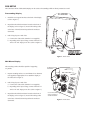
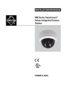
™
®
Integrated Camera Systems from Pelco
Congratulations on receiving Pelco’s Camclosure™ Point of Sale (POS) Display.
This display is provided to demonstrate the high quality, compact size, and
aesthetic value of Pelco’s Camclosure Integrated Camera Systems.
Your Point of Sales Display contains:
1 Pre-assembled POS Countertop/Wall Mount Display
1 ICS100 Series Surface Mount Dome
1 ICS150 Series In-ceiling Dome - Includes black and white
camera with 6mm lens
1 ICS200 Series Wedge Enclosure
1 ICS300 Series Positionable Enclosure
1 Placard - To place on top of demonstration monitor (not included)
2 Support brackets
The POS display includes a pre-wired standard resolution black & white camera
with 6mm lens, installed in the ICS150 in-ceiling dome. To demonstrate the
picture quality of the Camclosure Series, connect the power wires to power and
the video OUT connector to the video IN connector of a monitor.
NOTE: Monitor is not included with Point of Sale Display.
C2427M (1/01)
®
3500 Pelco Way, Clovis | CA 93612-5699 USA | www.pelco.com
North America & Canada (800) 289-9100 or FAX (800) 289-9150
International +1 (559) 292-1981 or FAX +1 (559) 348-1120
POS SETUP
The Camclosure Point of Sale (POS) Display can be used as a freestanding exhibit or directly mounted to a wall.
Freestanding Display
1.
Install the two support brackets to the back of the display
(refer to Figure 1).
2.
Reposition the ICS300 enclosure located on the front of
the display (refer to Figure 2). Loosen the locking collar
at the base of the ICS300 and reposition the enclosure
downward.
3.
Pull wiring for power and video.
a. Connect the video cable. (Monitor is not supplied.)
b. Depending on the input voltage, connect either the 12
VDC or 24 VAC input power wires (refer to Figure 1).
Figure 1. Back View
Wall Mount Display
The mounting surface should be capable of supporting
52 pounds.
1.
Prepare mounting surface. Use a minimum of two fasteners
(not supplied) of appropriate size to attach the display to
the wall (refer to Figure 1).
2.
Pull wiring for power and video.
a. Connect the video cable. (Monitor is not supplied.)
b. Depending on the input voltage, connect either the 12
VDC or 24 VAC input power wires (refer to Figure 1).
3.
Reposition the ICS300 enclosure located on the front of
the display (refer to Figure 2). Loosen the locking collar
at the base of the ICS300 and reposition the enclosure
downward.
ICS300 REPOSITION
DOWNWARD
ICS151-MA6 CONNECT
VIDEO & POWER TO
OPERATE CAMERA.
Figure 2. Front View