1
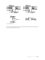
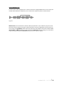
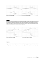
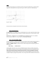
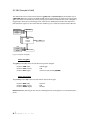
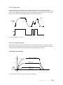
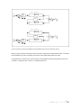
Four voltage levels (0 V, 1 V, 3 V, 5V) at the ”AMT“-input explain the voltage control of the envelope’s
final level (amount). The envelope can only be used to modulate the cutoff frequencies of the filters via
knobs (10) and (31). Further control capabilities of the multiplier will be covered later.
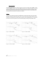
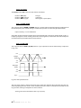
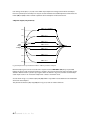
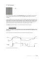
2. Bipolar output (only external):
AMT = 5 V / floating
5V
AMT = 4 V
3V
AMT = 3 V
1V
ENV
-output
-Voltage
AMT = 2.5 V
AMT = 2 V
-1 V
AMT = 1 V
-3 V
AMT = 0 V
-5 V
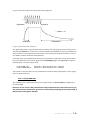
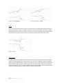
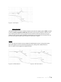
Fig. 9.5.6 Bipolar envelope modulation with the ”AMT“-input of the multiplier
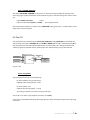
Both envelope signals can be accessed at the rearpanel socket ”ENV OUT“ (20). They are provided
bipolar (in positive and negative directions) as shown in fig. 9.5.6. The final level of the envelope can be
shifted in both directions - positive up, negative down. As shown in fig. 9.5.6, zero Volts at the multiplication input results in an inverted envelope with -5 Volts as maximum value.
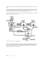
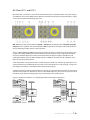
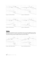
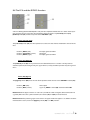
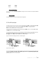
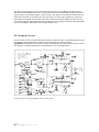
As also shown in fig. 9.5.1, switches (11) and (32) of ENV 1 resp. ENV2 2 select between two modulation
sources for the multiplier.
The position of switches (11) resp. (32) (left in fig. 9.5.1) leads to another function.
l
49 user manual e b b e
und
flut