1
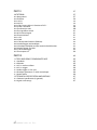
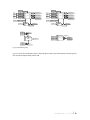
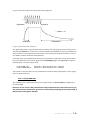
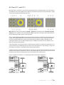
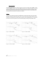
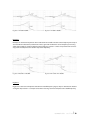
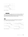
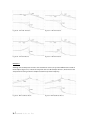
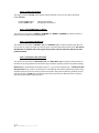
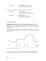
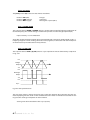
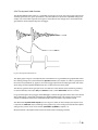
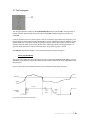
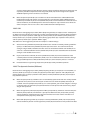
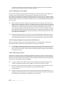
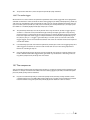
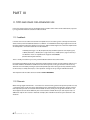
Triangle:
Saw:
Square:
+5 Volts
+5 Volts
- 5 Volts
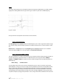
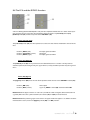
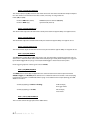
back: (4)(TIP) LFO OUT
On the rearpanel socket ”LFO OUT“ (4)(TIP) the LFO signal can be accessed with an output amplitude
of ±5 Volts.
front: (23a) LED
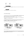
The blue LED follows the current waveform with it’s brightness.
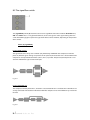
9.5 The AHR-envelopes
The AHR-envelopes contain the control elements (17), (18), (19) for ENV 1 and (25), (26), (27) for ENV
2 on the frontpanel and the rearpanel sockets (8), (10), (12) for ENV 1 and (9), (11), (13) for
ENV 2 and socket (20) for both envelope generators.
Internally, each VCF is prepatched to one envelope generator, ENV 1 to VCF 1 via knobs (10) and (12)
and ENV 2 to VCF 2 via knobs (31) and (33).
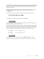
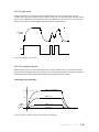
An envelope generator generates an one-shot voltage curve after receiving a trigger. When this curve
has ended, a new trigger is needed to restart the envelope. The envelopes offer two modes:
Re-Trigger-mode as AHR-envelope or Gate-mode as AR-envelope.
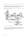
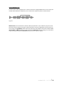
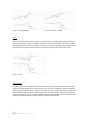
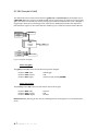
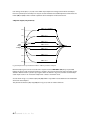
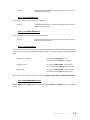
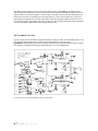
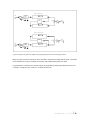
Fig. 9.5.1 shows the envelope generators as a block diagram.
ATTACK 1
(10t)
hold 1
(18)
HOLD 1
(10r)
release 1
(18)
RELEASE 1
(12r)
Trigger
ENV 1
multiplier
attack 1
(17)
A(H)R 2 (9r)
ENV 1 (fix level)
to VCA, VCF1-Resonance
ENV 1 (var level)
to VCF1-Frequency
ENV 1 OUT (20t)
(bip level)
TRIG 1 (8t)
DYN
attack 2
(25)
hold 2
(26)
HOLD 2
(11r)
release 2
(27)
RELEASE 2
(13r)
Trigger
dynamic
hold
AMT 1 (12t)
switch (11)
ENV 2 (fix level)
to VCA, VCF2-Resonance
ATTACK 2
(11t)
ENV 2
multiplier
A(H)R 1 (8r)
ENV 2 (var level)
to VCF2-Frequency
ENV 2 OUT (20r)
(bip level)
TRIG 2 (9t)
DYN
dynamic
hold
AMT 2 (13t)
switch (32)
Fig. 9.5.1 ENV 1 and ENV 2
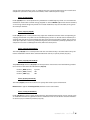
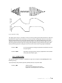
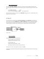
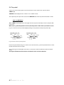
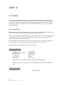
Fig. 9.5.2 shows the basic curve of an AHR-envelope. The times apply for the value ranges with the control elements [attack 1] (17), hold 1 (18), [release 1] (19) for ENV 1 resp. [attack 2] (25), [hold 2] (26),
[release 2] (27) for ENV 2 on the frontpanel.
user manual e b b e u n d f l u t
l 46