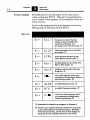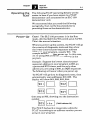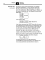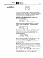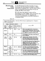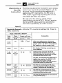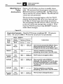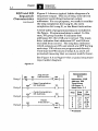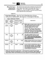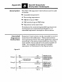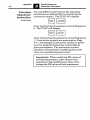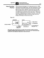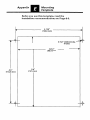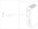
1
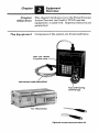
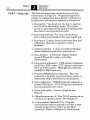
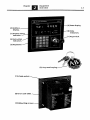
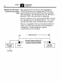
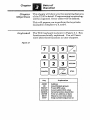
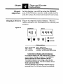
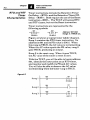
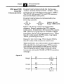
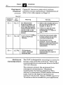
ALLEN-BRADLEY
A ROCKWELL INTERNATIONAL COMPANY
User's Manual
IMPORTANT INFORMATION
Solid state equipment has operational characteristics differing
from thoseof electromechanical equipment. Becauseof this, and
also because of the wide variety of uses forsolid state equipment,
all personsresponsible for applying this equipment must satisfy
themselves that each intended application
of this equipmentis
acceptable.
In no event will Allen-Bradley Companybe responsible or liable
for indirect or consequential damages resulting from the use or
application of this equipment.
The examples and diagrams in this manual are included
solely for
illustrative purposes. Because of the many variables and
requirements associated with any particular installation, AllenBradley Company cannotassume responsibility or liability
for
actual use based onthe examples and diagrams.
No patent liability is assumed
by Allen-Bradley Company with
respect to useof information, circuits, equipment, or software
described in this manual.
Reproduction of the contentsof this manual, in
whole or in part,
without written permission
of the Allen-Bradley Company is
prohibited.
0
1986 Allen-Bradley Company
WARNING and CAUTION Boxes
WARNINGS indicate that people maybe hurt if
procedures arenot followed properly. CAUTIONS
indicate that machinery may
be damaged or economic
loss can occur if procedures are not followed properly.
Both WARNINGS and CAUTIONS
0 Identify a possible trouble spot
0 Tell what causes the trouble
0 Give the resultof improper action
0 Tell how to avoid trouble
Page
1-1
Chapter Objectives . . . . . . . . . . . . . . . . . 2-1
The Equipment . . . . . . . . . . . . . . . . . . . 2-1
TCAT .
Features . . . . . . . . . . . . . . . . . . 2-2
Optional RemoteCommunication Kit . . . . . 2-4
Chapter Objectives . . . . . . . . . . . . . . . . 3-1
3-1
Keyboard . . . . . . . . . . . . . . . . . . . . . .
Mode Selection . . . . . . . . . . . . . . . . . . .3-2
Displays . . . . . . . . . . . . . . . . . . . . . . .
3-2
Display Instruction Symbols . . . . . . . . . 3-3
Error Codes . . . . . . . . . . . . . . . . . . . . .
3-4
Operating the TCAT . . . . . . . . . . . . . . . . 3-5
Power-Up. . . . . . . . . . . . . . . . . . . . . . .
3-5
Power-UpUsingAddress867
. . . . . . . . 3-8
Using the Address Key . . . . . . . . . . . . . . 3-9
. . . . . . . . . . . . . . 3- 10
Using the NEXTKey
Using the CANCELKey . . . . . . . . . . . . . 3-11
Using the PRESET. ACCUM. and STEP Keys
3-12
Protected PR and AC Values . . . . . . . . . . 3- 12
Chapter Objectives . . . . . . . . . . . . . . . . . 4-1
Displays Review . . . . . . . . . . . . . . . . . . . 4-1
RTO and RTF Timer Characteristics . . . . . . . 4-2
CTU and CTD Counter Characteristics . . . . . 4-3
Monitoring a Timer Instruction . . . . . . . . . 4-4
Monitoring a Counter Instruction. . . . . . . . 4-5
Modifying a Timer Instruction . . . . . . . . . . 4-6
Modifying a Counter Instruction . . . . . . . . 4-7
Using ENTER Key t o Reset AC Value t o Zero . 4-8
Chapter
5
Title
Page
Instructions
Sequencer
Chapter Objectives . . . . . . . . . . . . . . . . . 5-1
SQO and SQI Sequencer Characteristics . . . . 5-1
Monitoring a Sequencer Instruction . . . . . . 5-3
Modifying a Sequencer Step . . . . . . . . . . . 5-4
6
Outputs
and
Inputs
Monitoring
ChapterObjectives . . . . . . . . . . . . . . . . 6-1
i/O Monitoring Capabilities of theTCAT . . . 6-1
Address Group Numbers . . . . . . . . . . . . . 6-1
The TCAT Group Number Display . . . . . . . . 6-3
Monitoring Group NumberAddresses . . . . . 6-4
7
Specifications . . . . . . . . . . . . . . . . . 7-1
8
Installation
Chapter Objectives . . . . . . . . . . . . . . . . 8-1
Equipment Checkout . . . . . . . . . . . . . . . 8-1
Enclosure Considerations . . . . . . . . . . . . . 8-2
8-3
Mounting . . . . . . . . . . . . . . . . . . . . . .
Connecting the Cable . . . . . . . . . . . . . . . 8-4
Mounting Template . . . . . . . . . . . . . . . 8-5
Cleaning Recommendations . . . . . . . . . . . 8-6
Appendices
A -Using FineTime Base Contacts . . . . . . A-1
B -SpecialSequencer Instructions . . . . . . 6-1
C-Shift Register instructions . . . . . . . . . C-1
EEPROM Memory Module . . . . . . . . . D-1
D.
E -Mounting Template . . . . . . . . . . . . . E-1
The TimerKounterAccess Terminal (TCAT) is
used with the SLC 100 Programmable Controller.
I t is designed for mounting ina panel cutout,
usually thedoor of the controller enclosure.
mode, the
With theSLC 100 controller in the Run
TCAT provides access to programmed timer,
counter, and sequencer data. This allows
production, supervisory, and maintenance
people
to monitor this data “on-line”.
Data can also
be modified to accomodate
a process
or part change. A keyswitch helps prevent
unauthorized modifications.
This manual points out important features
of the
TCAT, then goes on to discuss operating details
as
they apply to timerlcountertsequencer data, and
the monitoringof I/O addresses.
You don’t need a detailed
knowledge of
programming to use theTCAT.
~~~~~~~
~
~
This chapter introducesyou to the TimerICounter
Access
~ Terminal
~ (we'll ~call it TCAT)
~
and wthe
@
equipment itis used with. Important features are
pointed out.
Components of the system are illustrated
below.
ii;:
*I
_,
-
K A T unit. Mounts
in a panel cutout.
Interconnect calble (detachable).
Optional remote communication kit.
TCAT - features
The following features are pointed out in the
illustration on Page 2-3. Programming terminology is explained in more detail in Chapter 3.
Installation information appears in Chapter
8.
1. Keyswitch. You must use the key
to operate
the TCAT in themodify mode. This helps
prevent unauthorized program modifications.
Keyswitch cover protects keyslot.
2. Keys and keyring. For your convenience,
error codes are printed on the keyring
ID tag.
3. Keyboard. Used to access and enter data and
addresses. Keys have positive, tactile
feedback.
4.Address display. 3-character digital display
shows addresses and other information.
5 . Data display. 4-character digital display
shows PR and
AC values, and other
information.
6. Instruction indicators. TME (green) indicates
a n RTO or RTF timer. CNT (green) indicates
a
CTU or CTD counter. SEQ (green) indicates
a n SQO or SQI sequencer.
7. Protect (PROT) status indicator. This red
indicator is lit
if the monitored instruction or
sequencer stepis protected in the program.
8. Data indicators. PRESET (green) indicates a
preset (PR) value.ACCUM (green) indicates
a n accumulator (AC) value.
9. Error code table. Listed in Englishand
French.
(4).The TCAT mounts ina n
10. Mounting screws
enclosure or panel cutout. See Chapter8.
11. Cable socket (labeled
CCl). Plug the
interconnect cable (supplied) into this socket
and the programmer socket
on the SLC
processor. Refer to Chapter8, Installation.
2-3
Address
display.
-
--
Protect status
indicator.
-(5) Data display.
4 8 ) Data
indicators.
.(1) Keyswitch.
Instruction/
indicators.
Keyboard..
i
No.
O p t i O d Remote The remote communication kit (Catalog
a
at
TCAT
the
locate
to
you
allows
1745-N2)
Communjcati.ion
#it remote distance (upto 4000 feet) from theSLC
100 controller. For distancesbeyond 100 feet, a
Series B SLC 100 controller is required.
of two unassembled DIN connecThe kit consists
below. You must
tors, pointed out in the figure
provide the cable anda suitable power supply.
The kitis supplied withan instruction sheet to
guide you thru the assembly and installation
procedures. Cable and power supply
specifications are included.
+-
4000 feet max.
r/
Remote Communication Kit
Consists of these two DIN
connectors(unassemb1ed)
Controller
AC input
aptea This chapter will show you the operating features
of the TCAT in detail. Programming
terminology
will be explained. Errorcodes will be defined.
This will prepare you to perform the keystroke
examples in Chapters4,5, and 6.
The TCAT keyboard is shown in Figure3.1. Key
functions are briefly explained.You will learn
more about these functions in later chapters.
Figure 3.1
Key
ADDR
110
PRESET
ACCUM
CANCEL
ENTER
NEXT
STEP
I
Explanation
Address
InputIOutput groups
Preset (PR)value
Accumulator (AC) value
Cancel previouskeystroke
Enter an address ordata
Move tonext instruction
Step number (sequencers)
I
/bk&
S@/ectiof) The keyswitch is shown at the right.
The keyslot is vertical, indicating
the MONITOR mode is in effect.
The TCAT will operate in thismode
with the key inserted orremoved.
With thekey inserted and turned
clockwise 90" (keyslot
horizontal),
the MODIFY mode is in effect. The
key cannot be removed in thismode.
Displays
Figure 3.2
ro
MODIFY
MONITOR
Figure 3.2 shows the digital displays andLED
indicators of the TCAT. The figure depictsa
typical display.
ADDRESS
I
1 9 0
I
Abbreviations
-
-
PROT Protected SEQ Sequencer
PRESET Preset (PR) Value
TME -Timer
ACCUM -Accumulator (AC) Value
CNT Counter
-
-
Explanation of displays andLED indicators
In this typical display, the TME indicator is lit, telling
us that a timer is being monitored. The ADDRESS
display indicatesthe timeraddress t o be 901.
The ACCUMindicator islit, telling us that theAC
value is being monitored. The DATAdisplay shows
the AC value t o be 999.9.
The PROT indicator is lit, telling us that the timer
is
protected (the AC or PR value cannotbe modified).
Display Instruction
Symbols
Various abbreviations and symbols appear in the
DATA display to indicate the timer, counter, and
sequencer instructions. These are summarized in
Figure 3.3.
Figure 3.3
r t o
Retentive On-Delaytimer instruction.
rtF
Retentive Off-Delay timer instruction.
[tu
Up-counter instruction.
Ctd
Down-counter instruction.
oEUU
Sequencer output instruction. Eventdriven. The last two digits (zeros in
this case) indicate the sequencer
group number.
OCUIl
I
EO1
I
COl
Sequencer output instruction.Timedriven. The last two digits (zeros in
this case) indicate the sequencer
group number.
Sequencer input instruction. Eventdriven. The last two digits (07 in
this case) indicate the sequencer
group number.
Sequencer input instruction.Timedriven. The last two digits (07 in
this case) indicate the sequencer
group number.
9'P
This is a prompt message applying to
address group numbers. It asks you to
enter a group number.
5tEP
This is a prompt message applyingto
sequencer instructions. It asks you to
enter thesequencer step number.
Error Codes Procedural errors and other errors can
occur
when using theTCAT. Figure 3.4explains the
error codes which appear in the display
when an
error occurs.
key
Error code explanations also appear on the
ID tag andon theback of the TCAT.
Figure 3.4
mode, orthe Auto/Manual
switch is in Manual, ora
processor error has occurred.@
E
5L c 2
Err
kc k
E
1d
E
fl d 2
E
n
Er r
5tEp
E
E
I
Error
discovered during
the
TCAT power-up self test. 0
Invalid address (not within the
901 to 932 range). @
Address not foundin the user
program. 0
This code appearswhen you
attempt tomodify data while in
the monitor mode.@
d
9r p
p
Communication error with the
processor. 0
t
Invalid sequencerstep.
@
Invalid I/O group number. @
This error code appears when
you attemptto modify data
which is protected. @
@ Remediesfor these errors appear in Chapter 8.
@ These errors indicate that you entered wrong data
or you attemptedan invalid procedure. Remedy:
Press the Cancel key,which returns the
display to
the point it was at before theerror was made.
Operatin9 the The following TCAT operating detailswill be
TCA T easier to learnif you have access to aTCAT
demonstrator unit connected to an SLC 100
demonstrator unit.
We recommend that you read thefollowing
paragraphs, thenverify the proceduresby
practicing themon the demonstrator.
Power-Up Case 1. The SLC 100 processor is in theRun
mode, with theMAN/AUTO switch setat AUTO.
This is the normal situation.
When you power-up the system, the
TCAT will go
show
thru a series of diagnostic tests and then
the lowest timer/counter/sequencer address
number inyour program, usually901. The
example below describes power-up. In this case,
we are using905 as the lowest address in the
program.
Example: Suppose the lowest timer/counter/
sequencer address in your program
is 905, an
unprotected RTO timer, and the
only other
address you are usingis 930, an SQO sequencer.
The following will occur when you power-up:
The TCAT will go thru itsdiagnostic tests, then
automatically scan addresses901-932. The
display will show 901,902,903,904:
then stopat 905, showing you the instruction
symbol:
F]
(TME indicator lit)
T h e T C A Tkeyboard is inoperative while the
TCAT is scanning
to an address number you are
using in your program.
Power-Up
(continued)
To move to your next instruction, you simply
press the NEXT key. If you do this while the
TCAT is still scanning, the display
will again
show the addresses. You might happen topick up
the scanat address 928; the display would show
928,929:
then stop at
930:
(.EOOi
(SEQ indicator lit)
Any time you press theNEXT key after the scan
is completed, the TCAT shows (in sequence) only
those instructionsyou are using in the program.
In this case, pressingNEXT repeatedlywould
alternately show instructions 905 and930.
Case 2. The SLC 100 processor is in theRun
mode, with theMAN/AUTO switch setat MAN.
When you power-up the system, theTCAT will go
thru its diagnostic tests and then
display:
-IErrI
I ~ L ICI
To clear this error, turn processor
the
AUTO/MAN switch to AUTO. The TCAT will
then scan addresses
as described in Case
1.
Power-Up
(continued)
Case 3. The SLC 100 processor is in some other
mode than Run.
When you power-up the system, the
TCAT will go
thru its diagnostic tests and then
display:
To clear this error,you must use thePocket
Programmer to place the
processor in the Run
mode. The TCAT will then operateas described
in Case1.
Case 4. Processor does not have
a user program
in memory, or the program
does not containany
timer, counter, or sequencer instructions.
When you power-up the system, theTCAT will go
thru its diagnostic tests, then scan addresses
901932. The following error code will then appear:
/Rdr21
To correct this error, enter
a program havinga
timer/counter/sequencer instruction,then place
the processor in the Run
mode.
Special Note - Fine Time Base Instructions:
If your program contains fine time base instructions (addresses869-8751,see Appendix A.
On power-up, the TCAT will go thru its
diagnostics checks, then
immediately display the
instruction in the rung containing address
867
(instead of scanning addresses until it reaches
the lowest instruction used in the program).
m u
Using the exampleabove, the displayshows:
0
(CNT, ACCUM indicators lit)
Note that theTCAT has gone directly to the AC
value of the instruction. We’ve designed address
867 to work this way for your convenience.
Using the
Address Key
This is a dual function key. Press once
it when
you want to enter an address. Press
it twice when
you want to enter anI/O group number. We’ll
explain theYO function in Chapter6.
Moving to another address: Suppose the
TCAT display shows
(CNT indicator lit)
and you want to move to address 915, an RTO
timer. Press ADDR (once). The display will
show:
The displaywill be flashing, promptingyou for
the lasttwo numbers of the address. Press
numeric keys1,5, then pressENTER. The
display will show:
.!?
E
i
l
2
(TME, ACCUM indicators lit)
The displayis showing you the AC value of the
instruction. This occurs automatically,
whenever you use theADDR key to move to
another address.
Mistakes: If youhappen to press theADDR key
twice, or press thewrong numeric key, or enter
an invalid address (error
code appears), press the
CANCEL key and try again.
Special Note - Fine Time Base Instructions:
If your program contains fine time base instructions (addresses869-8751,see Appendix A.
[Z]
Using the
NEXT Key
This key performs boththe NEXT and ENTER
functions. In the paragraph on
Power-Up (Page
3-6), we used it tomove to thenext address in the
user program. In the paragraph on Using the
Address Key (Page 3-9),we used it to enter an
address.
In thefollowing paragraph, we’ll show you how to
use the NEXT key tomove thru thetimer/
counterlsequencer addresses in theuser program.
In Chapter6 on monitoring inputs and outputs,
we will show you how to use theNEXT key to
move thru address group numbers.
Moving to the next address: Suppose your
program hasa timer, a counter, anda sequencer.
The addresses are 905,909, and 924 respectively.
The displayis showing the preset valueof the
timer:
nu
m u
90 5
3 0.0
(TME, PRESET indicators lit)
Press theNEXT key. The displaywill show
70 0
(CNT,PRESET indicators lit)
The display hasmoved to the counter instruction,
and itis showing the preset value. PressNEXT
again. The displaywill show the sequencer:
PI]
(SEQ,PRESET indicators lit)
The displayis showing the preset valueof the
current step.
3-1 1
Using the
NEXT Key
Two things are important to remember here:
0
(continued)
Pressing the NEXT key shows you the
addresses in numerical order, even if they do
not appear in numerical order in the user
program.
When moving to the next address, the display
shows the same type
of information that was
shown previously. In this case
it is the preset
value. It could also be the AC value or the
instruction symbol.
Special Note - Fine Time Base Instructions:
If your program contains fine time base instructions (addresses869-8751, see Appendix A.
Using the
CANCEL Key
CANCEL
The CANCEL key can
be used for three things:
Clear an error code. Press CANCEL to clear
an errorcode. Discussed on Page 3-4.
Show instruction symbol. When the display
is showing thePR or AC value, pressCANCEL
to display the instruction
symbol. For
example, if the PR value of timer 905 is shown,
nu
q 05
3 0.0
(TME, PRESET indicators lit)
pressing CANCEL will bring up the
instruction symbol:
(1
0
(TME indicator lit)
Cancel data. When the display is prompting
for numeric data (address,
I/O group, step
number, new AC or PR value) pressCANCEL
to cancel the data entry.
Discussed on Page
3-9.
Using the
PRESET, ACCUM,
and STEP Keys
The functionof these keysis described in the
keystroke examplesof Chapters 4 and 5.
Protected PR The PR andAC values of a timer or counter can
and AC Values be protected in the user program. Thisis also
true of the PR value of a sequencer step. These
protected values cannotbe changed with the
TCAT.
When an instruction withprotected PR and AC
values is displayed by the TCAT, the PROT LED
will be lit to indicate the protected status.
Timer and Counter
Chapter In this chapter,you will be using the PRESET
Objectives and ACCUM keys to monitorand modify the PR
and AC values of a timer and counter instruction.
Displays Review
Figure 4.1
DATA
Figure 4.1 depicts a typical display. This is a
repeat of Figure 3.2,included here to refresh your
memory.
ADDRESS
Abbreviations
-
PROT- Protected SEQ Sequencer
TME -Timer
PRESET- Preset (PR) Value
ACCUM Accumulator (AC) Value
CNT Counter
-
-
Explanation of displays andLED indicators
In this typical
display, the TME indicator is lit, telling
us that a timer is being monitored. The ADDRESS
display indicatesthe timeraddress to be 901.
The ACCUMindicator is lit, telling us that theAC
value is being monitored. The DATA display shows
the AC value to be 999.9.
The PROT indicator is lit, telling us that thetimer is
protected (theAC or PR value cannot be modified).
Timer and Counter
Instructions
4 -2
RTO and RTf
Timer
Characteristics
Timer instructions include the Retentive Timer
On-Delay -(RTO)- and the Retentive TimerOffDelay -(RTF)-. Both require the use of the Reset
instruction -(RST)-. The TCAT will accessRTO
and RTF timers, but
not the Reset instruction.
Timer instructions are represented
by the
following symbols:
901
-( RTF )-
PR 400.0
PR 400.0
Address: 901-932
Range: 0.1-999.9 sec.
Figure 4.2 shows a typical timer ladder diagram.
Rung 1contains theRTO timer instruction. Its
address is 901 and its PR value300.0.
is When
this rung is
TRUE, the AC value is incrementing.
When theAC value equals thePR value, rung2
goes TRUE, producingan output.
c
goes TRUE,
Rung 3 is the reset rung. When it
the AC value of the timeris reset to zero.
With theTCAT, you will be able to locate address
901, identify the instruction
as an RTO timer,
and monitor andmodify its PR and AC values.
You will also be able to observethe AC value
incrementing when the timer rung
is TRUE.
Figure 4.2
Rung 1
Rung 2
Rung 3
(-I
R';:
)-
PR 300.0
gOw
( - fO"
T :
+
RAC 0
CTU and CPD
Counter
cteristics
Ckara
Counter instructions include the Up Counter
-(CTU)- and the Down Counter -(CTD)-. Both
require the useof the Reset instruction-(RST)-.
The TCAT will access CTU and CTD counters,
but not the Reset instruction.
Counter instructions are represented
by the
following symbols:
901
PR 1000
4PRCTD
)1000
Address: 901-932
Range: 1-9999 counts
Figure 4.3 shows a typical counter ladder
diagram. Rung 1contains theCTU counter
instruction. Its addressis 910 and its PRvalue is
888. When this rung makes
a FALSE to TRUE
transition, theAC value increasesby one. When
the AC value equals the PR value, rung
2 goes
TRUE, producingan output.
it goes TRUE,
Rung 3 is the reset rung. When
the AC value of the counteris reset to ten.
With theTCAT, you will be able to locate address
910, identify the instruction as
a CTU counter,
and monitor and
modify its PR andAC values.
You will also be able to observe AC
thevalue
increment with each
FALSE to TRUE transition
of rung 1.
Figure 4.3
Rung 2
Rung 3
RAC 10
mer and Counter
Monitoring a
Timer
/nstroction
In the following keystroke example, we are
assuming that the program contains anRTO
instruction a t address 914. Its PR value is 300.0,
and it is protected (meaningthat we can not
modify the PR or AC value).
We will enter the address,
which will be
identified as a timer (TME). We will monitor the
AC and PR values, and then
identify the
instruction specifically as an RTO (Retentive
On-Delay) timer.
Figure 4.4
Keystroke Example - Monitor RTO timer ataddress 914. Preset is
300.0, protected.
Timer and Counter
~~~~0~~~~
a The following keystroke example is quite similar
to the timer keystroke example (Figure
4.4).In
this case,we are assuming that address
914
applies toa CTU instruction. Its PR value is
3000, and it is
protected (meaningthat we can
not modify the PR or AC value).
We will enter the address,
which will be
identified as a counter (CNT).We will monitor
identify the
the AC and PR values, and then
instruction specifically a s a CTU counter.
Figure 4.5
Keystroke Example
3060, protected..
- Monitor CTU counter at address 914. Preset is
T
Mode: MONITOR or MODIFY
Press
these
keys
Apply
power
These
LEDs will
be lit
CNT
ADDR
None
1.4,
ENTER
CNT,
ACCUM,
PROT
-
CNT,
PRESET,
PROT
ACCUM
CNT,
ACCUM,
PROT
CANCEL
Address
i
Explanation
Data
I
90 I Ctd
When you applypower, the lowest
timer/counter/sequencer addressis displayed, unless-I/[- 867 is used. Address
901 applies t o a down counter (Ctd).
The display is flashing, prompting you
for an address.
9 111
0
Address 914 is entered. The TCAT
automatically monitors the AC value.
Value increasesfor each FALSE t o TRUE
transition of the counter rung.
The CNT LED indicates that address 914
applies t o a counter; the ACCUM LED
indicates the AC value is being
monitored; the PROT LED indicates the
AC and PR values are protected.
PRESET
-
Display will show
CNT,
PROT
The TCATis monitoring thePR value.
You can go back to the
AC value if you
choose. Just pressthe ACCUM key.
9 19
9 I 1 1 [tu
0
The TCATis monitoring theAC value.
Value increasesfor each FALSE t o TRUE
transition of the counter rung.
The TCATis identifying theinstruction as
an up counter (CTU).
Timer and Counter
Modifying a
Timer
/nstructjon
Figure 4.6 will show you how to modify timer
data. We assume that the program containsa n
RTO instruction at address 901. Its PR value is
100.0, and its AC value is 999.9. The PR and AC
values are not protected.
The keystroke example begins with TCAT
the
PR value (you learned how
display showing the
to do this in the previous keystroke examples).
We will changethe PR value to 300.0, then go on
to the AC value and change that
to 222.2. Note
that theTCAT must be in theMODIFY modeto
make these changes.
Figure4.6
-
Keystroke Example Modify RTO timer at address 901. PR value is
100.0. AC d u e is 999.9.PR and AC values are not protected.
1 1 zit,
Mode: MODIFY
Press
these
These
LEDs will
PRESET
Display will show
Address
3.0.0.0
ENTER
1
TME,
PRESET
I
Data
1
90 I
9 c] I 3 0 0.0
9 0 I g 9 g .g
ACCUM
90 1
TME,
ACCUM
You havejust pressedthe PRESET key to
display the PR value of timer 901. To
change the PR value, pressPRESETagain.
---.-
ACCUM The TME,
ACCU M
2,2,2,2
ENTER
Explanation
9 0 I I 0 0.0
PRESET
keys
I
1
---
1
.-
g 0 I 2 2 2 .z
The four underlines are flashing,
prompting youto enter a new PR value.
The PRvalue ischanged to300.0.
current AC value of 999.9 is
displayed. We assumethat theAC value
is not incrementing (timer rung FALSE)
To enter a new AC value, press ACCUMa
second time.
The four underlines are flashing,
prompting you t o enter a new AC value.
The AC value is changed t o 222.2.
Figure 4.7 will showyou howto modify counter
data (similar to
modifying timer data). We
assume that the program contains
CTU
a
instruction at address 901. Its PR value is1000,
and its AC value is 9999. The PR and AC values
are not protected.
The keystroke example begins with TCAT
the
display showing the
PR value (you learned how
to do this in previous keystroke examples).
We
will change thePR value to 3000, then go on to
the AC value and change that
to 2222. Note that
the TCAT must be in theMODIFY mode.
Figure 4.7
-
Modify CTU counter at address 901. PR value
is 1000. AC value is 9999. PR and AC valuesare not protected.
Mode: MODIFY
Explanation
You have just pressed the PRESET key t o
display the PR value of counter 901. To
change the PR value, pressPRESET again.
The four underlines are flashing,
prompting youto enter a new PR value.
The PR value is changed to 3000.
The current AC value of 9999 is
displayed. To enter a new AC value,
press A C C U M a second time.
The four underlines
flashing, are
prompting youto enter a new AC value.
ACCUM
-
2,2,2,2
ENTER
CNT,
ACCUM
g0 I 2 22 2
The AC value is changed to 2222.
Timer and Counter
Using the ENTER
~e~ to Reset the
A c value to Zero
Figure 4.8 will show you how to use the
ENTER
key to change the
AC value of a timer to zero (the
PR value canbe changed to zeroin the same
way). Arbitrarily, we have specified that theAC
value is incrementing.
The AC value (andPR value) of a counter canbe
changed to zero in this same
way.
Figure 4.8
Keystroke Example- Change the AC value of timer 901 to zero. The
PR and AC values are not protected.
AC value i s incrementing.
Mode: MODIFY
1
Press
these
keys
These
LEDs will
be lit
ACCUM
TME,
ACCUM
ACCUM
TME,
ACCUM
ENTER
I
TME,
ACCUM
Display will show
Address
I
I
Data
9 fl I 2 2 2 .z
I
90 I -
gfl I
Explanation
--.-
You have just pressedthe ACCUM key.
The AC value happenst o be at 222.2, and
incrementing. Suppose you want to
"reset" the AC value to zero.
The underlines are flashing,
prompting
you to enter a new AC value. To enter a
value of zero, just press ENTER.
The AC value is incrementing from zero.
er
5
I
~
~
risfics
In this chapter,you will be monitoring thePR
and AC values of the individual stepsof a
Sequencer instruction. You will also modify the
PR valueof a sequencer step.
Sequencer instructions include the Sequencer
Output
f
-(SQO)f
and
~ the Sequencer
~
~ Input
-(SQI)-. Both require the use of the Reset
instruction -(RST)-. The TCAT will access SQO
and SQI sequencers, butnot the Reset
instruction.
Sequencer instructionsare represented by the
following symbols:
-(
)-
4*QI F
901
Address: 901-932
100 stepsmaximurn.
The Sequencer Output
(SQO) instruction can
control the ON/OFF status of up to 8 outputs for
up to100 steps. The ON/OFF status of outputs
for each step is programmed.
The Sequencer Input
(SQI) instruction differs
from the SQO instruction in that the status
of up
to 8 inputs is programmed, producingan output
only whenthe statusof external inputs matches
the programmed data
for the particular step.
Sequencers canbe time-driven or event-driven.
With time-driven sequencers, each step functions
similar to timer instructions, involving
ACan
value anda programmed PR value. In the same
way, the event-driven sequencer functions
similar to counter instructions.
You will find further operating details and
programming information in the User’s Manual
for the SLC 100 Programmable Controller.
Here we are concerned onlywith monitoring the
PR and AC values of the individual steps, and
modifying PR values.
S O 0 and SO/ Figure 5.1 shows a typical ladder diagramof a
Sequencer sequencer output. This is a 5-step, time-driven
Characteristics sequencer controlling 6 external output
(continued)
addresses. For our purposes, we needn’t consider
the stepcompletion bit (rung2), the cycle
completion bit (rung
3), or the Reset instruction.
A brief tableof programmed data is included in
the figure. Programmed datais coded. In this
case, 110 group number0 indicates that
addresses 011 thru 018 are involved. The mask
data indicates that addresses
017 and 018 are
excluded from control. The step data indicates
which outputs are
ON and which are OFF during
each step. PR values are programmed directly.
Note that thePR values of steps 0 , 2 , and 4 are
protected (meaningthat we cannot modify them).
See Figure 5.3
on Page 5-4 for a typical sequencer
input ladder diagram.
Figure 5.1
PROGRAMMED
DATA
Instruction: SQO
Address: 904
Time-Driven
If0Group: 0
Mask Data: 2, F
Rung 1
Step Completion
Rung 2
Rung 3
/Cycle Completion
Bit Address
Rung 4
RAC 0
* Protected
Chapter
Sequencer
Instructions
5-3
Monitoring a The following keystroke example assumes that
sequencer the program contains the sequencershown in
/nstruction Figure 5.1. We will monitor the AC value,
identify the step number, monitor PR
thevalue,
then identify the instruction.
Figure 5.2
-
Keystroke Example Monitor the5-step SequencerOutput
instruction at address 904. See Figure 5.1 for programmed data.
Mode: MONITOR or MODIFY
I
Modifying a The following keystroke example assumes that
Sequencer Step the program contains the sequencershown in
Figure 5.3. We will modify the PR value of step
2, then attemptto modify the PR value of step 0.
Figure 5.4
-
Keystroke Example Modify theSequencer Input instructiona t
address 903. See Figure 5.3 for programmed data.Address 903 is
the lowest timer/counter/sequenceraddress programmed.
Mode: MODIFY
Explanation
Apply
SEQ
power
g 03
E01
Address 903 is displayed. The 1s t digit of
the instruction symbol indicatesSQI; the
2nd indicatesevent-driven; The 3rd and
4th indicate I/O group number 7 .
To access step
a number, the AC or PR
value mustfirst be displayed. We've
called up the PR value (protected).
PRESET,
PROT
0 , is displayed.
Current step number,
STEP
Press
again t o another
select
step.
The display is flashing, prompting you
for a steDnumber.
Chapter In this chapter,you will be monitoring the status
Objectives of external inputs and external outputs.You will
also monitorthe statusof instructions having
internal addresses.
nitoring In most applications you will find it useful to
jlitjes of monitor the ordoff status of input devices (limit
the T ~ A T switches, selector switches etc.) and output
devices (motor starters, relays,solenoids).
You may also want to monitor the status
of
instructions having internal addresses. For
example, the status and
overflow bits of counters
could be used with output energize instructions
having internal addresses.You will be able to
observe how the counter affects this internal
logic of your program.
umbers
An address group number represents eight
addresses. In most cases, these addresses are
consecutive (001 thru 008,011 thru 018).
There are70 group numbers. They correspond to
the group numbers established
for programming
sequencer instructions. For ourpurposes,we are
using themto access user program addresses.
Figure 6.1 on the following page lists the70
address group numbers.
dress Croup
Number5
icontjnue~)
Group number 0 gives you access to addresses of
external outputs of the SLC 100 processor; group
numbers 1thru 6 give you access to addresses of
external outputsof expansion units. Similarly,
group numbers7 thru 15give you access to
addresses of external inputsof the processor and
expansion units. These 16 groups are themost
widely used in TCAT applications.
Figure 6.1
External
input
Addresses
Group
No.
External
Output
Addresses
internal
Addresses
Group
No.
0
1
2
011-016
111-116
211-216
017-018
117-118
217-218
7
8
9
001 -008
101-108
201-208
3
4
5
6
311-316
411-416
511-516
611-616
317-318
41 7-41 8
517-518
617-618
10
11
12
301-308
401-408
501-508
601-608
14
009-010
109-110
209-210
15
309-310
409-410
509-510
609-610
Group Numbers 38
thru 69
Groups 38thru 69 correspondto addresses 901
thru 932 respectively. They are used
in special
sequencer instruction techniques.
The TCAT display for these group numbers does
a r e p r e s e n t external input/outputaddresses
orinternal addresses. instead, it shows you the
individual bitsof a BCD counter (the count
correspondsto the sequencer step number).
-
13
Group
No.
Internal
Addresses
16
17
18
701-708
709-716
717-724
19
20
21
725-732
733-740
741-748
22
23
24
749-756
757-764
765-772
25
26
27
773-780
781-788
789-796
28
29
30
797-804
805-812
813-820
31
32
33
821-828
829-836
837-844
34
35
36
37 0
845-852
853-860
861-868
869-876
0 These arefine time base
addresses and the
auto/manual switch bit.
ADDR - I/O key twice
P Pressing the dual function
will
prompt
you
for
a
group
number. Afteryou
Y
enter a number and press ENTER, the
TCAT will
show youthe group number anda representation
of the statusof the corresponding8 addresses.
A typicalTCAT display is shown in Figure6.2.
0.
This displayshows address group number
Figure 6.1 indicates that symbols
the
in the data
window apply to addresses011 thru 018. In this
group, addresses 011,012,013,014,015, and
016
apply to external outputs
of the SLC 100
processor unit. Addresses 017 and 018are
internal addresses.
Addresses appear in numerical order, with the
lowest address on the right. If a symbol is “low”
(011,013,014,015, and0181, the instructiona t
that address isOFF (or the address not
is used).
If a symbol is “high”, the instruction
is ON.
Figure6.2
i(-I1
~
JT,Al
I
,~
ON position
OFF position
Group number
8 linesrepresent addresses 011,
012,013,014,015,016,017,018.
The lowest address
(011 in this case) is
always on the right.
This display tells you thatdevices connectedt o output
terminals 12 and 16 of the processor unit are energizedor ON.
If you have output devices connectedt o terminals 11,13,14,
and 15, they are OFF.
The display alsotells you that
an output energize instruction at
internal address 017is ON. If you are usingan output energize
instruction at address018, it is OFF.
Monitoring
Group Number
Addresses
In the following keystroke example,we will
access a group number, use the
ADDR - I/O key
to access another group number, useNEXT
the
key to access successive group numbers,
then
return to the original instruction.
Figure 6.3
Keystroke Example - Monitor address group numbers 0,15, and 17.
Return to the original display.
Explanation
contains a down counter at address 901,
and address867 is not used.
~~
~~~~~
VO, I/O,
None
0.
ENTER
None
I
-- q r p
The display is promting you for
a group
number.
I
I
I
I
None
l/O,I/O,
1.5.
ENTER
Group 0 is selected. Addresses 01 1,012,
013,014,015,016,017,018are
displayed. 012 and 014 areON.
Group 15 is selected. Addresses 309,
310,409,410,509,510,609,610are
displayed. 409 and 610 are ON.
Pressingthe NEXT key twice has moved
the display t o group 17, applying to
internal addresses 709,710,711,712,
713,714,715.716. Instructionsat
addresses710,713,714,715areON.
90 I C t d
CNT
110.
CANCEL
I
I
Pressing thesekeys has taken us back to
the initialdisplay, the downcounter at
address 901. We could also have
accessed someother timedcounterl
sequencer addressby pressing UO,the
new address, then ENTER.
I
Display:
Discrete Light EmittingDiodes (LEDs) and 7-segment LED
readouts.
Keyboard:
Sealed and embossed. 16 momentary push keyswith tactile
feedback.
Keyswitch:
Two-position keylock switch
with cover.
Modes of Operation: Monitor and modify.
Error Code Identification Table:
On backof unit and on keyringID tag.
Interconnect Cable:
6-foot (1.8m) cable. Plug-in connectors mateTCAT and
processor unit.
Operating Power:
The TCAT receives power fromthe SLC 100 programmable
controller via the 6-foot interconnect
cable.
Remote connection (up t o 4000 feet) is possible using a
separate power supply rated a t 10.8 t o 26.4 VDC, 4 watts (for
UL listing, powersupply must beNEC Class 2). Use Belden cable
style 9503 or equivalent. The Remote Communication Kit
(Catalog No. 1745-N2) includes the necessary DIN connectors
and the installation instructions.
Ambient Temperature Range:
0"to 60" C (operating). -40" t o 85" C (storage).
Humidity Rating: 5 t o 95% (without condensation).
Noise Immunity: NEMA Standard ICs 2-230.
Vibration (mountedin enclosure door orpanel):
0.006 inch peak t o peak displacement, 1 .Og peak (max)
acceleration, 1 Hr/axis.
Certification:
Meets NEMAType12 and 13 and IEC 529 IP65 enclosure
applications. UL listed. CSA certified.
Overall Dimensions:
5.50" (139.7 mm) wide x 6.0" (152.4 mm) high x 2.89"
(73.41mm) deep. Weight: 13 ounces.
Chapter This chapter explainshow to check out theTCAT
Objectives prior to installation andhow to install theTCAT
in an enclosure cutout.
Equipment Before you install theTCAT, checkit for external
Checkout damage which might have occurred during
shipment. Thenpower it up tocheck for possible
internal damage.
To power up the TCAT, you will need accessto a n
energized SLC 100 processor. Power-up
procedure:
1. Energize the processor. Place the
processor in
the Runmode with thepocket programmer.
Turn theAuto/Manual switchto Auto.
2. Disconnect power tothe processor. Unplug the
pocket programmer.
3. Plug one end
of the interconnectcable
(supplied with the
TCAT) in thesocket on the
top of the TCAT and the other end in the
programmer socketon the processor. Cable
connectors are keyed to guard against
improper insertion. Make sure the spring
latch is engaged to secure theconnector in the
socket.
4. Energize the processor. TheTCAT should
operate as described in Chapter3 on Pages 3-5
to 3-8.
5 . If the TCAT display shows any of the following
3 error messages,follow the procedures listed
in Figure8.1.
Err
Err
Err
5LC I
5LC2
tCRt
Equipment
Checkout
Figure 8.1 lists error codes which indicate
possible internal malfunctions. Explanations of
other errorcodes appear on Page
3-4.
Figure 8. ?
ADDRESS
Display
Display
Err
5LC I
Err
SLC2
DATA
Meaning
Remedy
SLC 100 processor
1. Refer t o the remedial advice in
the SLC 100 User’s Manual,
hardware problem. As
Chapter 21, Fig. 21.2.
notedon Page 3-4, this
error code also appears
2. If the errorcode still exists,
if the processor is not in
contact your local A-B
the Run mode, orthe
representativefor repair or
Auto/Manual switchis in
replacement.
Manual.
Communication problem
between TCAT and
processor.
1. Check the interconnect cable
t o make certain it is securely
connected a t both ends.
2. Recycle power to the
processor. If error code still
appears, contact yourlocal A-8
representativefor repair or
replacement.
Err
tCRt
Enclosure
TCAT hardware
problem. Detected
during self-test.
Contact your local A-B
representative forrepair or
replacement.
The TCAT is designed for mounting ina cutout in
the door of the controller enclosure.Follow all
recommendations on enclosures listed in SLC
the
100 User’s Manual.
The enclosure protects the equipment from
atmospheric contamination. Standards
established by the National Electrical
Manufacturer’s Association (NEMA) define enclosure
types, based on the degree
of protection an
enclosure will provide. Select a NEMA type 12 or
13 enclosure that is suitable
for your application.
Installation
Mounting
8-3
Figure 8.2 shows the cutout dimensionsfor the
TCAT. We have also includeda mounting
template (AppendixE) for your convenience.In
locating the cutout on the
enclosure door,
Provide adequate clearance behind the
enclosure door and above and
below the TCAT
housing. See note on ventilationbelow.
Position theTCAT so that stresswill not be
exerted on the interconnect
cable whenthe
door is opened.
Before drilling, make certain that all
power to
the equipment within the
enclosure is
disconnected. Make certain the drill bit
will
not make contact with equipment and cause
damage.
Important note on ventilation: To keep
the TCAT temperature within thespecified
range, cooling air in the
enclosure must be
between 0-60°C.
-
Allow 3 inches clearance above and
6 inches
clearance belowthe TCAT housing.
All four studson the TCAT should be grounded to
the enclosuredoor. To accomplish this, scrape
away the paint at the
points where eachKEPS
nut (supplied) makes contact with inside
the of
the enclosure. Important: The torque requirement on theKEPS nut is in-lbs.
6
Tighten so
that theTCAT bezel just contacts the
surface of
the enclosure.
Caution: The TCAT has ventilation holes
for cooling on
the upper and
lower portions of
the backcover. If you make additional holes
in theenclosure, make sure the ventilation
holes are covered to protect against metal
chips entering the
TCAT housing.
Connecting A cable instruction sheet is provided with the
the Cable TCAT unit. It is important that you read and
follow these instructions when connecting the
TCAT to a n SLC-100 processor.
One end of the interconnect cable plugs into the
socket on the top
of the TCAT and the other end
plugs into the programmer socket
on the
processor. Cable connectorsare keyed toguard
against improper insertion. Make sure the
spring latchis engaged to secure the connector.
cable is live. We recommend that you
disconnect the cable
at the SLC end, to guard
against connector short circuits and
possible
damage to the processor.
Figure 8.2
4.125"
(104.8 mm)
3.812"
(96.8 mm)
0
4.50"
(114.3 mm)
0
Approximate cutout and drilling
dimensions forthe K A T
anin9 The following materials arerecommended for
dons cleaning the front panelof the TCAT.
1. Detergent Solution. (Typical household type
cleaner.)
2. Isopropyl Alcohol.
3. Methanol.
WARNING: Solutions containing the
following substances mustnot be used:
Chlorinated Hydrocarbons
Toluene
Acetone
Ammonia
Description
Fine Time Base instructionsallow you to
program timers with greater resolution than the
0.1 second resolution providedby standard
timers. I/O group 37 includes fine time base bit
addresses 869 through 875 (address 869 is a scan
counter; addresses874 and 875 count in intervals
of 0.5 and 1.0 seconds respectively). The
measured scan timeof your SLC 100 program
determines which of the remaining Fine Time
Base instructionsyou can use.
Caution: The scan timeof the SLC 100 is
slightly increased during the
following
operations of the TCAT.
1. During theTCAT power up scan discussed
on Page3-5.
2. Each time theNEXT keyis pushed to
select a new address to monitor.
3. When the Address key and the numeric
keys are used to select a new address to
monitor.
An increase in scan time may
cause Fine
Time Base instructionsto operate
inaccurately.
Description The SLC 100 sequencer instructions canbe used
to create:
Cascaded sequencers
0
Reversing sequencers
SQI driving an SQO
0
SQI monitoring an SQO step
Sequencer jump operation
Procedures for monitoring/modifying sequencer
instructions are explained in Chapter
5. A
cascaded sequencer exampleis shown below.
Cascaded
Sequencer
/nstructjon
Sequencer instructions canbe cascaded to control
more than 8 bit addresses. These instructions
will sometimes share the same addresses, operate
according to the same rung conditions, have the
same preset value and have the same number
of
steps. An example of this type of cascaded
sequencer is illustrated in the figure
below.
Special Sequencer
E-2
Cascaded You can differentiate between the sequencer
Sequencer instructions at address
901 by monitoring the
instruction
symbol.
The
TCAT will display
Instruction
(continued)
when monitoring the sequencer controlling group
0. The TCAT will display
when monitoring the sequencer controlling group
1. (Instruction symbols are explained on Page
3-3.) Accessing the instruction symbol on power
key is described in
up or by using the Cancel
previous chapters. The instructionsymbol
should be checked
before modifying the preset
value of a cascaded sequencer step.
Important: When modifying PR values of
cascaded sequencers, make certain that
sequencer rung conditions are false, then
change thePR values of both sequencers.
step Number
Display
When programming reversing sequencers, SQI
monitoring an SQO step, and the sequencerjump
operation, special sequencer groups38 through
69 must be used. Special sequencer groups 38
through 69 are binary counters that display the
current step number
for the operation. The step
number is displayed in binary notationwith the
least significant digit in the far right
position.
Figure B.2 below illustrates this.
Description
With a shift register instruction, status data
enters an &bit register is
and
automatically
shifted through the register from
one bit address
to the next on a time
or event-driven basis. A
sequencer instruction isused to control the shift
rate as shown in the figure
below.
Figure C.1
Tirne-driven
Group no.: Any
Rung 1
Rung 2
Rung 3
Rung4
4q< , G by: (
ZCL
Step 0 data: Any
clock0rate
Step
preset: Shift
ZCL
Tirne-driven shift rightregister -The TCAT can be
used to modify thepreset value of step 0 which is the
shift clock rate.
The shiftclock rate of a shift register instruction
can be modified with theTCAT. In the figure
above, the shift register
a t address 18 is
controlled by sequencer 901. The preset valueof
sequencer 901 controls the shiftclock rate. This
preset canbe modified with theTCAT. See the
keystroke examplefor modifying sequencersteps
in Chapter5 on Page 5-4 for details.
~
~
The EEPROM
S
moduleC is a n optional
~ device ~
which plugs into theSLC 100 processor unit.
With theEEPROM you can:
0
Save the contentsof the RAM memory, for
storage purposes.
0
Load the contentsof the EEPROM memory
into the processorRAM.
If you have a n EEPROM module installed and
you have modified data with the
TCAT and you
wish the modified data to be saved in the
EEPROM, you must do so before disconnecting
power. Do this by exchanging theTCAT with the
pocket programmer andfollowing the procedure
described in Chapter16 of the SLC 100 User’s
Manual (Publication1745-800).
After saving the contents
of the RAM, youcan
remove power.
n
We’ve provided the following template (3 copies)
for your convenience in mounting the
TCAT.
Before you use the template, read the
installation recommendations on Page 8-3.
Before you use this template, read the
installation recommendationson Page 8-3.
4.125"
(104.8 mm)
4
-
f
0.152" (3.86mm)dia.'
4 holes
3.81 2"
(96.8mm)
I
4.5"
(1 14.3 mm)
5.0"
(127.0 mm)
-
Before you use this template, readthe
installation recommendationson Page 8-3.
t
-
A
0.152" (3.86mm) dia.'
4 holes
3.812"
(96.8 mm)
I
4.5"
(114.3 mm)
b
4.125"
(104.8 mm)
5.0"
(127.0 mm)
-
Before youuse this template, read the
installation recommendations on Page 8-3.
-
A
0.152" (3.86mm)dia.'
4 holes
3.812"
(96.8 mm)
I
4.5"
(114.3 mm)
b
4.1 25"
(1 04.8 mm)
4
5.0"
(127.0 mm)
+
ALLEN-BRADLEY
A ROCKWELL INTERNATIONAL COMPANY
industrial Control Division
Milwaukee, Wisconsin53204
Publication 1745-850 -April, 1986
@
40065-311-01(A)