1
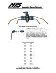
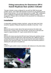
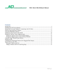
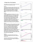
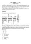
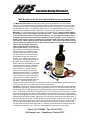
Innovative Racing Electronics
MPS Dry Nitrous Kit For Fuel Injected Motorcycles Instructions
The MPS Dry Nitrous Kit was designed to easily increase horsepower of a fuel injected
motorcycle. These Dry Nitrous Kits exploit the ability of electronic fuel injection to deliver extra
fuel at a touch of a button. The kits yield between 20 and 40 + horsepower. They are strictly for
fuel injected motorcycles. The MPS Dry Nitrous Kit For Fuel Injected Motorcycles is for use in
closed course competition events only and are not for use on any public street or highway
Mounting – To mount the bottle you will need to find a suitable spot. Danger: Nitrous bottles
can explode. Never exceed 1000 lbs of bottle pressure. Nitrous pressures over 1000 lbs
or so can prevent the nitrous solenoid from opening. Do not expose the bottle to direct
sunlight or leave the bottle enclosed in a container in direct sunlight. If you mount your
bottle in your trunk or under the seat be sure to take the bottle out before letting the bike
sit in the sun. Nitrous gains pressure with temperature. Do not mount the bottle near any
source of heat. You will need to find a place that the bottle is out of sight, away from heat,
secure, and accessible. Above the
motor, under the tank is not a good
spot in other words! The nitrous bottle
has no siphon tube installed in the bottle.
When the bottle is mounted the valve
should be the lowest part of the bottle.
The better job you can do positioning
your bottle the better the system will
function. The system needs to pick up
liquid nitrous. The optimum position is
the bottle valve toward the ground.
Siphon tubes can be installed if you wish
to mount the bottle upright. Mount the
nitrous nozzle in a ram air tube at the
front of the airbox. With the nitrous
nozzle in this location the nitrous will
pass through the air filter. To install the
nozzle mount in the ram air tube, drill a
7/16” hole where you want your nitrous
nozzle mounted. Push the bolt half of
the nozzle mount through the hole from
the inside. Screw the nut half of the
nozzle mount on from the outside to complete the nozzle mount installation. Screw in the nitrous
nozzle till snug, then turn enough to aim it directly at the airbox.
Plumbing – The Nitrous solenoid inlet port is connected directly to the nitrous supply bottle via a
#4 AN swivel type fitting. Locate the push in style fitting on the “out” side of the nitrous solenoid.
Cut the end of the 1/8” high pressure line provided squarely using a razor blade or plastic tubing
cutter. Push the line as far into the fitting as it will go. Pull out to lock the line in place. To remove
the line from the fitting, push down on the retaining ring on the fitting and the line. While holding
down the retaining ring pull the line out of the fitting. Route the line to the nitrous nozzle following
existing wiring whenever possible. Make sure you route this line away from any extreme heat. It
will melt! Slide the blue b-nut over the line with the thread facing the nozzle side of the line. Next
slide the cone ferrule onto the line with the cone facing the nozzle end of the line. Cut the end of
the line to the final length squarely with a razor blade or tubing cutter. Push the end of the line
securely into the funnel portion of the #28 jet. Insert the jet into the nitrous nozzle and snug the
b-nut then turn it about a ½ to 1 full turn to secure the jet and line to the nitrous nozzle.
Phone: 321.972.8282 – Fax: 321.972.5123
380 Orange Lane – Casselberry, Florida 32707
Innovative Racing Electronics
Wire The Horn/Shifter – Starter/Nitrous Control Box
Note: The Black, White, and Blue will not be used if you don’t have an air shifter or
your bike has a horn that switches power. The switch swapper will only work for air
shifters on bikes that switch ground with the horn button.
•
•
•
•
•
•
•
•
•
•
•
•
Locate the harness coming out of your left handlebar switch pod.
Carefully slice back the protective covering around the harness in a convenient spot.
Locate the horn switch wire. Hayabusa will be the solid black wire. ZX12 will be a black
wire with a white tracer. Other models consult your service manual or call us.
Cut this wire.
Black Wire - Locate the end that runs to the switch and connect it to the black wire on
the controller harness
White Wire - Locate the end that goes toward the main wire harness and connect it to
the white wire on the controller
Blue Wire - Connect the blue wire to the blue wire on the MPS Sport Bike Electronic
Engine Kill and the negative side of the electric air valve as shown in the wire diagram.
Locate the harness coming out of your right handlebar switch pod.
Carefully slice back the protective covering around the harness in a convenient spot.
Locate the starter switch wire. Hayabusa and GSXR1000 will be a yellow wire with a
green tracer. ZX12 will be a blue wire with a white tracer. Other models consult your
service manual or call us.
Cut this wire.
) the switch and connect it to the yellow wire on
Yellow Wire - Locate the end that runs to
the controller harness
Orange Wire - Locate the end that goes toward the main wire harness and connect it to
the orange wire on the controller
Red Wire - Connect the red wire to the nitrous solenoid positive as shown in the wire
diagram.
Black
Black
Ground
To Starter Solenoid Through Factory Wire Harness
Nitrous Solenoid
Horn
Factory Starter Switch
Red
Orange
Yellow
Black
White
Blue
Factory Horn Switch
Black
Black
To Horn Through Factory Wire Harness
Brown Wires
To Negative Side
Of Each Coil
Blue
Black
Red
Electric Air Valve
Ground
Ignition Switched 12V
MPS Sport Bike Engine Kill
Wiring Diagram
Phone: 321.972.8282 – Fax: 321.972.5123
380 Orange Lane – Casselberry, Florida 32707
Shifter
&
Nitrous
Note: Horn position is
always with the toggle
arm toward the short
side of the box.
Innovative Racing Electronics
Factory Horn Switch Wire Colors
Hayabusa = Solid Black
ZX12R = Black with White tracer
Factory Starter Switch Wire Colors
Hayabusa = Yellow with Green tracer
ZX12R = Blue with White tracer
Note: To prevent harmful operation of the nitrous when rev limiter is engaged we recommend a
MSD RPM P/N 2-15-00-0550 switch. Check with us for proper calibration for your application.
You may also need a Tach adapter P/N 1-0271 as well. Wire the red on the rpm switch to ignition
switched 12 volt power, the black on the rpm switch to ground, the white on the rpm switch to the
tach adapter white, and the tach adapter four greens to the negative side of each coil. Next you
will replace the ground lead on the Horn/Nitrous Control with the gray wire on the rpm switch.
The gray wire should be the only source of ground for the nitrous solenoid.
Testing The System – First, turn of the nitrous bottle valve. Now turn on the key and arm the
nitrous. With your hand on the nitrous solenoid, push the starter button quickly. You should hear
and feel the nitrous solenoid open. Next flip the nitrous arm switch to the starter position and
push the starter button. This should engage the starter and not activate the nitrous solenoid.
Operation – The nitrous bottle weighs 2.2 lbs. empty and 3.2 lbs.full. Weighing the bottle is the
only way to tell if the bottle is full or empty. Pressure is not an indicator of how much nitrous is
left in the bottle. We highly recommend dynoing your bike before taking it to the track. Here are
a few tips to tuning and operating the system. Never use the nitrous at anything other than full
throttle operation. You will need a minimum of 90
) octane fuel. Do not use any product that
advances the ignition timing more than stock. A Power Commander is recommended to deliver
extra fuel at full throttle. Starting as rich is the safest tuning method. Damage can result when
the rev limiter is activated while on nitrous. Avoid the rev limiter on nitrous or install the RPM
switch to prevent it from happening. Use of the larger included nitrous jets should be done only
after the smaller jets are used successfully.
If you have any more questions we have a Frequently Asked Questions page at our web site as
well as the telephone tech support. Thank you for your purchase of this MPS product. All
products sold by MPS are for use at closed course competition events and not for use on public
streets or highways.
Phone: 321.972.8282 – Fax: 321.972.5123
380 Orange Lane – Casselberry, Florida 32707