1
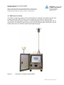
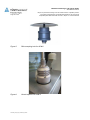
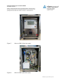
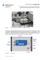
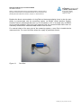
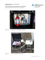
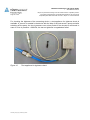
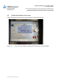
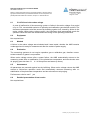
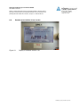
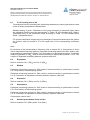
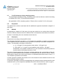
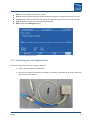
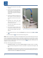
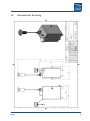
3. Lift the inlet tube off the virtual
impactor.
4. Connect the leak testing instrument
(Fig. 24) with the control cable socket
on the APM-2. The 7-pole socket is located on the front panel of the APM-2
control unit.
5. Power up the APM-2 by turning on the
main switch on the front panel and
the switch on the front of the control
unit.
6. Disconnect the coarse filter (with
tube) from the zero air port on the
left-hand side of the unit.
7. Insert the closure plug into the socket
at the zero air port.
8. Join the leak testing instrument with
the APM-2 by inserting the hose fitting
into the virtual impactor inlet port
(Fig. 25).
Fig. 25: Connecting the leak testing instrument
9. At the APM-2 control unit, call up the Leaking Test menu with menu items Setup → Leaking
Test.
10. Click on menu item Inlet to start the automatic testing process.
NOTE: If there is any vacuum in the device at the beginning of the test, then the testing cycle cannot be
started. The appropriate message will appear in the display, requesting that the device first be vented.
To do so, briefly detach the fitting on the gas hose from the adaptor at the virtual impactor and then
reconnect the hose. To begin the test cycle, select and confirm the Start menu item. The leak test is not
available in all versions of the device.
The steps in the testing process follow this sequence:
1. Generating a vacuum: The message “Leak test starting” will appear briefly in the display.
The internal pump will generate a vacuum in the APM-2 to a pressure level of approx. 300
hPa.
2. Testing phase: The testing phase will commence once the vacuum has been generated. During this period, the vacuum in the system will be monitored continuously by the sensors in
the device and shown as the PGas value in the display.
38
APM-2