1
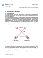
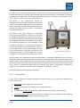
The light of a laser diode illuminates there a measurement volume defined by the optical beam path.
The light reflected by the aerosol particles within this measurement volume is recorded by the detector
positioned at an angle of 90°. The voltage signal generated and then amplified by the detector represents a direct measure for the mass concentration of
the aerosol in the measurement volume (01000μg/m³). For the zero point adjustment, filtered air
is fed to the scattered light sensor via the switching
device at periodic intervals. The data determined are
stored in the device memory as well as – if provided –
on an SD memory card.
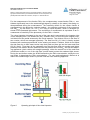
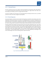
The physics of the light scattering on particulates
causes aerosol particles with a diameter on the order
of the light wavelength used – based on their mass –
to scatter the light the most efficiently. That means
they supply the greatest contribution to the signal.
The maximum sensitivity for the wavelength of 650
nm used in the device is in a particle size range from
0.5 to 1 μm. Because of this characteristic, there are
limits to application of simple scattered light photometry for measurement of the PM10 concentration. The
measurement signal of a scattered light sensor used in
outside air is primarily dominated by the PM2.5 fraction.
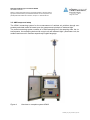
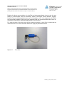
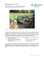
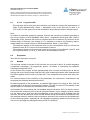
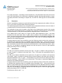
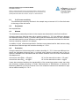
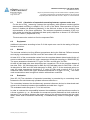
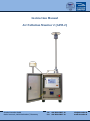
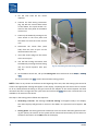
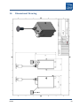
Fig. 2: Front side of APM-2
Based on mass, the complementary coarse fraction PM2.5-10 contributes significantly less to the scattered light signal and is therefore underrepresented in the measurement. The sensitivity deficit in the
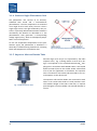
coarse fraction is thus compensated for in the device by a simple process: via selective enrichment of
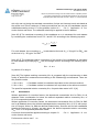
the concentration of the PM2.5-10 fraction by a factor of 3.3/0.2=16.5 by means of a virtual impactor (see
3.1.3.), which is connected upstream from the scattered light sensor. Concentration enrichment is
equivalent to an increase in sensitivity of the photometry for the PM2.5-10 fraction.
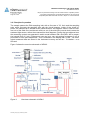
The system consists of the following components:
3.1.1. Control Unit
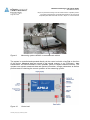
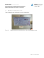
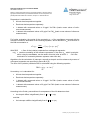
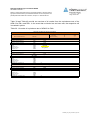
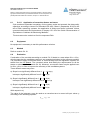
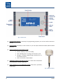
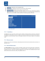
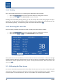
All the system settings are entered at the APM-2 control unit (Fig. 3). The unit has the following elements and functions:
Main switch used to switch the unit on and off
Jog dial to select functions and to enter or change parameters
An illuminated graphic display showing system functions, parameters, data and alarms
SD memory card slot for automatic storage of sampling data and parameters and for updating
the equipment firmware (also for the filter changer unit)
APM-2
11